Page 1331 of 3051

4 CHECK GROUND CIRCUIT
1. Turn ignition switch ªOFFº.
2. Disconnect camshaft position sensor harness connector.
3. Check harness continuity between CMPS terminal 5 and engine ground.
Refer to ªWiring Diagramº, EC-903.
Continuity should exist.
4. Also check harness for short to power.
OK or NG
OK©GO TO 5.
NG©Repair open circuit or short to power in harness or connectors.
5 CHECK INPUT SIGNAL CIRCUIT-I
1. Disconnect ECM harness connector.
2. Check harness continuity between ECM terminal 35 and CMPS terminal 6.
Refer to ªWiring Diagramº, EC-903.
Continuity should exist.
3. Also check harness for short to ground and short to power.
OK or NG
OK©GO TO 6.
NG©Repair open circuit or short to ground or short to power in harness or connectors.
6 CHECK IGNITION COIL, POWER TRANSISTOR
Refer to ªComponent Inspectionº, EC-907.
OK or NG
OK©GO TO 7.
NG©Replace malfunctioning component(s).
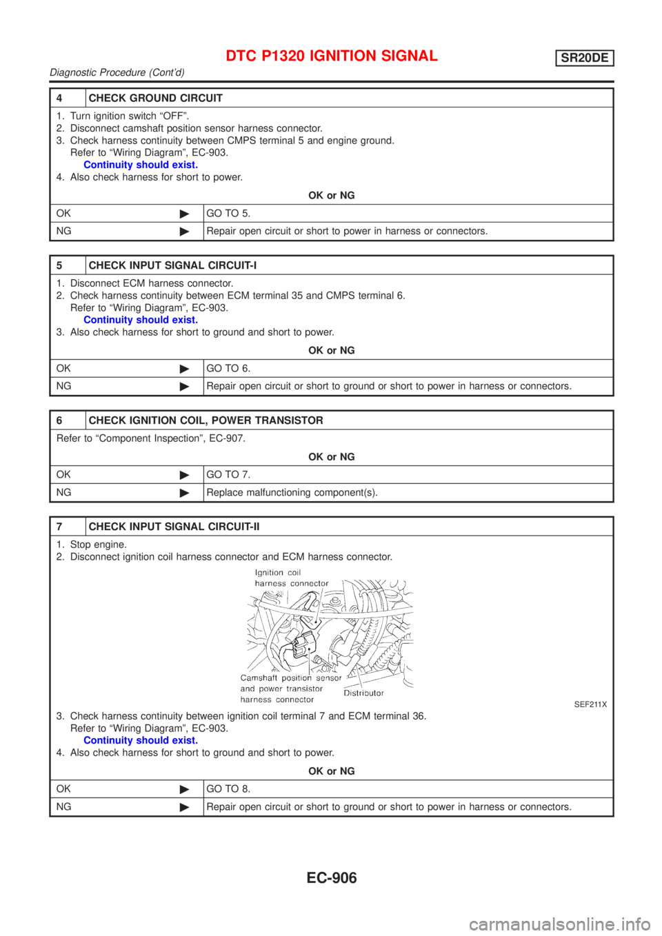
7 CHECK INPUT SIGNAL CIRCUIT-II
1. Stop engine.
2. Disconnect ignition coil harness connector and ECM harness connector.
SEF211X
3. Check harness continuity between ignition coil terminal 7 and ECM terminal 36.
Refer to ªWiring Diagramº, EC-903.
Continuity should exist.
4. Also check harness for short to ground and short to power.
OK or NG
OK©GO TO 8.
NG©Repair open circuit or short to ground or short to power in harness or connectors.
DTC P1320 IGNITION SIGNALSR20DE
Diagnostic Procedure (Cont'd)
EC-906
Page 1336 of 3051
Wiring DiagramNLEC1921MODELS WITH ECM IN ENGINE COMPARTMENTNLEC1921S01
YEC698
DTC P1336 CRANKSHAFT POSITION SENSOR (CKPS) (OBD)
(COG)
SR20DE
Wiring Diagram
EC-911
Page 1337 of 3051
MODELS WITH ECM IN CABINNLEC1921S02
YEC921
DTC P1336 CRANKSHAFT POSITION SENSOR (CKPS) (OBD)
(COG)
SR20DE
Wiring Diagram (Cont'd)
EC-912
Page 1338 of 3051

Diagnostic ProcedureNLEC1922
1 RETIGHTEN GROUND SCREWS
1. Turn ignition switch ªOFFº.
2. Loosen and retighten engine ground screws.
©GO TO 2.
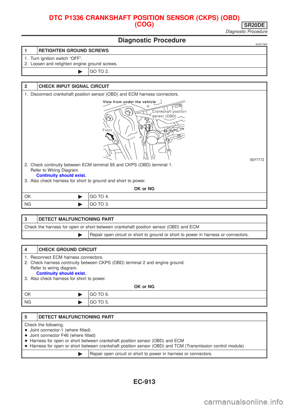
2 CHECK INPUT SIGNAL CIRCUIT
1. Disconnect crankshaft position sensor (OBD) and ECM harness connectors.
SEF777Z
2. Check continuity between ECM terminal 65 and CKPS (OBD) terminal 1.
Refer to Wiring Diagram.
Continuity should exist.
3. Also check harness for short to ground and short to power.
OK or NG
OK©GO TO 4.
NG©GO TO 3.
3 DETECT MALFUNCTIONING PART
Check the harness for open or short between crankshaft position sensor (OBD) and ECM
©Repair open circuit or short to ground or short to power in harness or connectors.
4 CHECK GROUND CIRCUIT
1. Reconnect ECM harness connectors.
2. Check harness continuity between CKPS (OBD) terminal 2 and engine ground.
Refer to wiring diagram.
Continuity should exist.
3. Also check harness for short to power.
OK or NG
OK©GO TO 6.
NG©GO TO 5.
5 DETECT MALFUNCTIONING PART
Check the following.
+Joint connector-1 (where fitted)
+Joint connector F46 (where fitted)
+Harness for open or short between crankshaft position sensor (OBD) and ECM
+Harness for open or short between crankshaft position sensor (OBD) and TCM (Transmission control module)
©Repair open circuit or short to power in harness or connectors.
DTC P1336 CRANKSHAFT POSITION SENSOR (CKPS) (OBD)
(COG)
SR20DE
Diagnostic Procedure
EC-913
Page 1343 of 3051
Wiring DiagramNLEC1630
YEC708
DTC P1401 EGR TEMPERATURE SENSOR (WHERE FITTED)SR20DE
Wiring Diagram
EC-918
Page 1344 of 3051
Diagnostic ProcedureNLEC1631
1 CHECK POWER SUPPLY
1. Turn ignition switch ªOFFº.
2. Disconnect EGR temperature sensor harness connector.
SEF216X
3. Turn ignition switch ªONº.
4. Check voltage between EGR temperature sensor terminal 2 and ground with CONSULT-II or tester.
SEF896X
OK or NG
OK©GO TO 2.
NG©Repair harness or connectors.
2 CHECK GROUND CIRCUIT
1. Turn ignition switch ªOFFº.
2. Check harness continuity between EGR temperature sensor terminal 1 and engine ground.
Refer to wiring diagram.
Continuity should exist.
3. Also check harness for short to power.
OK or NG
OK©GO TO 4.
NG©GO TO 3.
3 DETECT MALFUNCTIONING PART
Check the following.
+Joint connector-1
+Harness for open or short between EGR temperature sensor and ECM
+Harness for open or short between TCM (Transmission Control Module) and ECM
©Repair open circuit or short to power in harness or connector.
DTC P1401 EGR TEMPERATURE SENSOR (WHERE FITTED)SR20DE
Diagnostic Procedure
EC-919
Page 1350 of 3051
Wiring DiagramNLEC1638
YEC700
DTC P1402 EGR FUNCTION (OPEN) (WHERE FITTED)SR20DE
Wiring Diagram
EC-925
Page 1351 of 3051

Diagnostic ProcedureNLEC1639
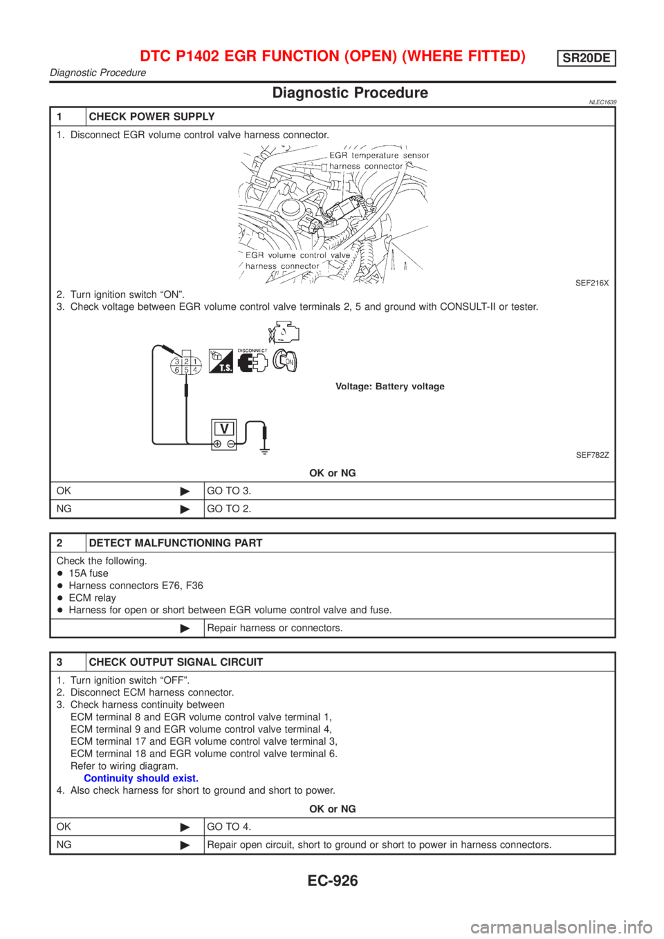
1 CHECK POWER SUPPLY
1. Disconnect EGR volume control valve harness connector.
SEF216X
2. Turn ignition switch ªONº.
3. Check voltage between EGR volume control valve terminals 2, 5 and ground with CONSULT-II or tester.
SEF782Z
OK or NG
OK©GO TO 3.
NG©GO TO 2.
2 DETECT MALFUNCTIONING PART
Check the following.
+15A fuse
+Harness connectors E76, F36
+ECM relay
+Harness for open or short between EGR volume control valve and fuse.
©Repair harness or connectors.
3 CHECK OUTPUT SIGNAL CIRCUIT
1. Turn ignition switch ªOFFº.
2. Disconnect ECM harness connector.
3. Check harness continuity between
ECM terminal 8 and EGR volume control valve terminal 1,
ECM terminal 9 and EGR volume control valve terminal 4,
ECM terminal 17 and EGR volume control valve terminal 3,
ECM terminal 18 and EGR volume control valve terminal 6.
Refer to wiring diagram.
Continuity should exist.
4. Also check harness for short to ground and short to power.
OK or NG
OK©GO TO 4.
NG©Repair open circuit, short to ground or short to power in harness connectors.
DTC P1402 EGR FUNCTION (OPEN) (WHERE FITTED)SR20DE
Diagnostic Procedure
EC-926