Page 1408 of 3051

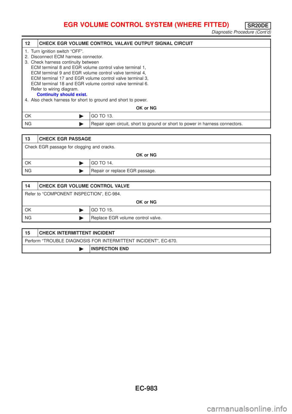
12 CHECK EGR VOLUME CONTROL VALAVE OUTPUT SIGNAL CIRCUIT
1. Turn ignition switch ªOFFº.
2. Disconnect ECM harness connector.
3. Check harness continuity between
ECM terminal 8 and EGR volume control valve terminal 1,
ECM terminal 9 and EGR volume control valve terminal 4,
ECM terminal 17 and EGR volume control valve terminal 3,
ECM terminal 18 and EGR volume control valve terminal 6.
Refer to wiring diagram.
Continuity should exist.
4. Also check harness for short to ground and short to power.
OK or NG
OK©GO TO 13.
NG©Repair open circuit, short to ground or short to power in harness connectors.
13 CHECK EGR PASSAGE
Check EGR passage for clogging and cracks.
OK or NG
OK©GO TO 14.
NG©Repair or replace EGR passage.
14 CHECK EGR VOLUME CONTROL VALVE
Refer to ªCOMPONENT INSPECTIONº, EC-984.
OK or NG
OK©GO TO 15.
NG©Replace EGR volume control valve.
15 CHECK INTERMITTENT INCIDENT
Perform ªTROUBLE DIAGNOSIS FOR INTERMITTENT INCIDENTº, EC-670.
©INSPECTION END
EGR VOLUME CONTROL SYSTEM (WHERE FITTED)SR20DE
Diagnostic Procedure (Cont'd)
EC-983
Page 1413 of 3051
Wiring DiagramNLEC1832MODELS WITH ECM IN ENGINE COMPARTMENTNLEC1832S01
YEC758
EVAP CANISTER PURGE VOLUME CONTROL SOLENOID
VALVE
SR20DE
Wiring Diagram
EC-988
Page 1414 of 3051
MODELS WITH ECM IN CABINNLEC1832S02
YEC936
EVAP CANISTER PURGE VOLUME CONTROL SOLENOID
VALVE
SR20DE
Wiring Diagram (Cont'd)
EC-989
Page 1418 of 3051

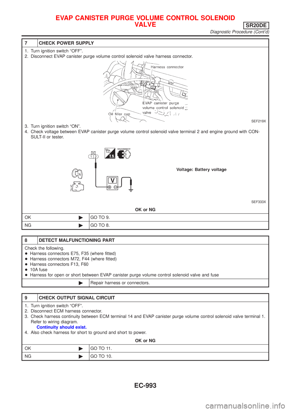
7 CHECK POWER SUPPLY
1. Turn ignition switch ªOFFº.
2. Disconnect EVAP canister purge volume control solenoid valve harness connector.
SEF219X
3. Turn ignition switch ªONº.
4. Check voltage between EVAP canister purge volume control solenoid valve terminal 2 and engine ground with CON-
SULT-II or tester.
SEF333X
OK or NG
OK©GO TO 9.
NG©GO TO 8.
8 DETECT MALFUNCTIONING PART
Check the following.
+Harness connectors E75, F35 (where fitted)
+Harness connectors M72, F44 (where fitted)
+Harness connectors F13, F60
+10A fuse
+Harness for open or short between EVAP canister purge volume control solenoid valve and fuse
©Repair harness or connectors.
9 CHECK OUTPUT SIGNAL CIRCUIT
1. Turn ignition switch ªOFFº.
2. Disconnect ECM harness connector.
3. Check harness continuity between ECM terminal 14 and EVAP canister purge volume control solenoid valve terminal 1.
Refer to wiring diagram.
Continuity should exist.
4. Also check harness for short to ground and short to power.
OK or NG
OK©GO TO 11.
NG©GO TO 10.
EVAP CANISTER PURGE VOLUME CONTROL SOLENOID
VALVE
SR20DE
Diagnostic Procedure (Cont'd)
EC-993
Page 1422 of 3051
Wiring DiagramNLEC1841MODELS WITH ECM IN ENGINE COMPARTMENTNLEC1841S01
YEC759
IDLE AIR CONTROL VALVE (IACV) Ð
AUXILIARY AIR CONTROL (AAC) VALVE
SR20DE
Wiring Diagram
EC-997
Page 1423 of 3051
MODELS WITH ECM IN CABINNLEC1841S02
YEC937
IDLE AIR CONTROL VALVE (IACV) Ð
AUXILIARY AIR CONTROL (AAC) VALVE
SR20DE
Wiring Diagram (Cont'd)
EC-998
Page 1425 of 3051

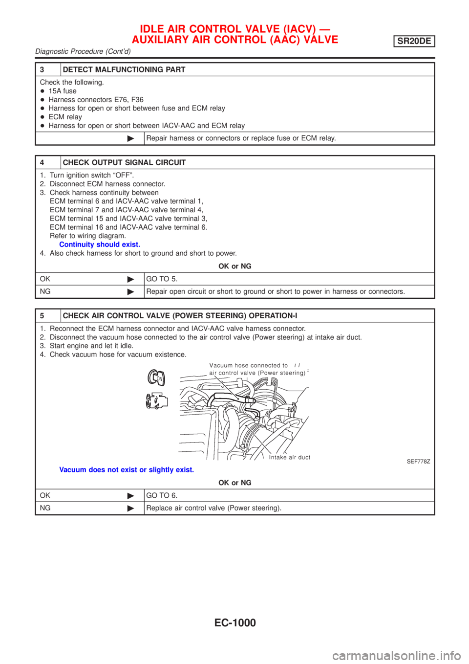
3 DETECT MALFUNCTIONING PART
Check the following.
+15A fuse
+Harness connectors E76, F36
+Harness for open or short between fuse and ECM relay
+ECM relay
+Harness for open or short between IACV-AAC and ECM relay
©Repair harness or connectors or replace fuse or ECM relay.
4 CHECK OUTPUT SIGNAL CIRCUIT
1. Turn ignition switch ªOFFº.
2. Disconnect ECM harness connector.
3. Check harness continuity between
ECM terminal 6 and IACV-AAC valve terminal 1,
ECM terminal 7 and IACV-AAC valve terminal 4,
ECM terminal 15 and IACV-AAC valve terminal 3,
ECM terminal 16 and IACV-AAC valve terminal 6.
Refer to wiring diagram.
Continuity should exist.
4. Also check harness for short to ground and short to power.
OK or NG
OK©GO TO 5.
NG©Repair open circuit or short to ground or short to power in harness or connectors.
5 CHECK AIR CONTROL VALVE (POWER STEERING) OPERATION-I
1. Reconnect the ECM harness connector and IACV-AAC valve harness connector.
2. Disconnect the vacuum hose connected to the air control valve (Power steering) at intake air duct.
3. Start engine and let it idle.
4. Check vacuum hose for vacuum existence.
SEF778Z
Vacuum does not exist or slightly exist.
OK or NG
OK©GO TO 6.
NG©Replace air control valve (Power steering).
IDLE AIR CONTROL VALVE (IACV) Ð
AUXILIARY AIR CONTROL (AAC) VALVE
SR20DE
Diagnostic Procedure (Cont'd)
EC-1000
Page 1431 of 3051
Wiring DiagramNLEC1927MODELS WITH ECM IN ENGINE COMPARTMENTNLEC1927S01
YEC761
IGNITION SIGNALSR20DE
Wiring Diagram
EC-1006