Page 1448 of 3051
MODELS WITH ECM IN CABINNLEC1858S02
YEC940
INJECTORSR20DE
Wiring Diagram (Cont'd)
EC-1023
Page 1450 of 3051

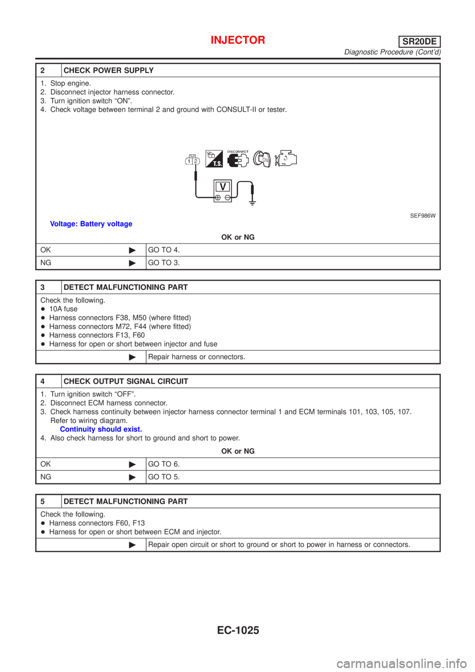
2 CHECK POWER SUPPLY
1. Stop engine.
2. Disconnect injector harness connector.
3. Turn ignition switch ªONº.
4. Check voltage between terminal 2 and ground with CONSULT-II or tester.
SEF986W
Voltage: Battery voltage
OK or NG
OK©GO TO 4.
NG©GO TO 3.
3 DETECT MALFUNCTIONING PART
Check the following.
+10A fuse
+Harness connectors F38, M50 (where fitted)
+Harness connectors M72, F44 (where fitted)
+Harness connectors F13, F60
+Harness for open or short between injector and fuse
©Repair harness or connectors.
4 CHECK OUTPUT SIGNAL CIRCUIT
1. Turn ignition switch ªOFFº.
2. Disconnect ECM harness connector.
3. Check harness continuity between injector harness connector terminal 1 and ECM terminals 101, 103, 105, 107.
Refer to wiring diagram.
Continuity should exist.
4. Also check harness for short to ground and short to power.
OK or NG
OK©GO TO 6.
NG©GO TO 5.
5 DETECT MALFUNCTIONING PART
Check the following.
+Harness connectors F60, F13
+Harness for open or short between ECM and injector.
©Repair open circuit or short to ground or short to power in harness or connectors.
INJECTORSR20DE
Diagnostic Procedure (Cont'd)
EC-1025
Page 1453 of 3051
Wiring DiagramNLEC1863MODELS WITH ECM IN ENGINE COMPARTMENTNLEC1863S01
YEC713
START SIGNALSR20DE
Wiring Diagram
EC-1028
Page 1454 of 3051
MODELS WITH ECM IN CABINNLEC1863S02
YEC941
START SIGNALSR20DE
Wiring Diagram (Cont'd)
EC-1029
Page 1459 of 3051
Wiring DiagramNLEC1869MODELS WITH ECM IN ENGINE COMPARTMENTNLEC1869S01
YEC714
FUEL PUMPSR20DE
Wiring Diagram
EC-1034
Page 1460 of 3051
MODELS WITH ECM IN CABINNLEC1869S02
YEC942
FUEL PUMPSR20DE
Wiring Diagram (Cont'd)
EC-1035
Page 1462 of 3051

3 DETECT MALFUNCTIONING PART
Check the following.
+10A fuse
+15A fuse
+Harness for open or short between fuse and fuel pump relay
©Repair harness or connectors.
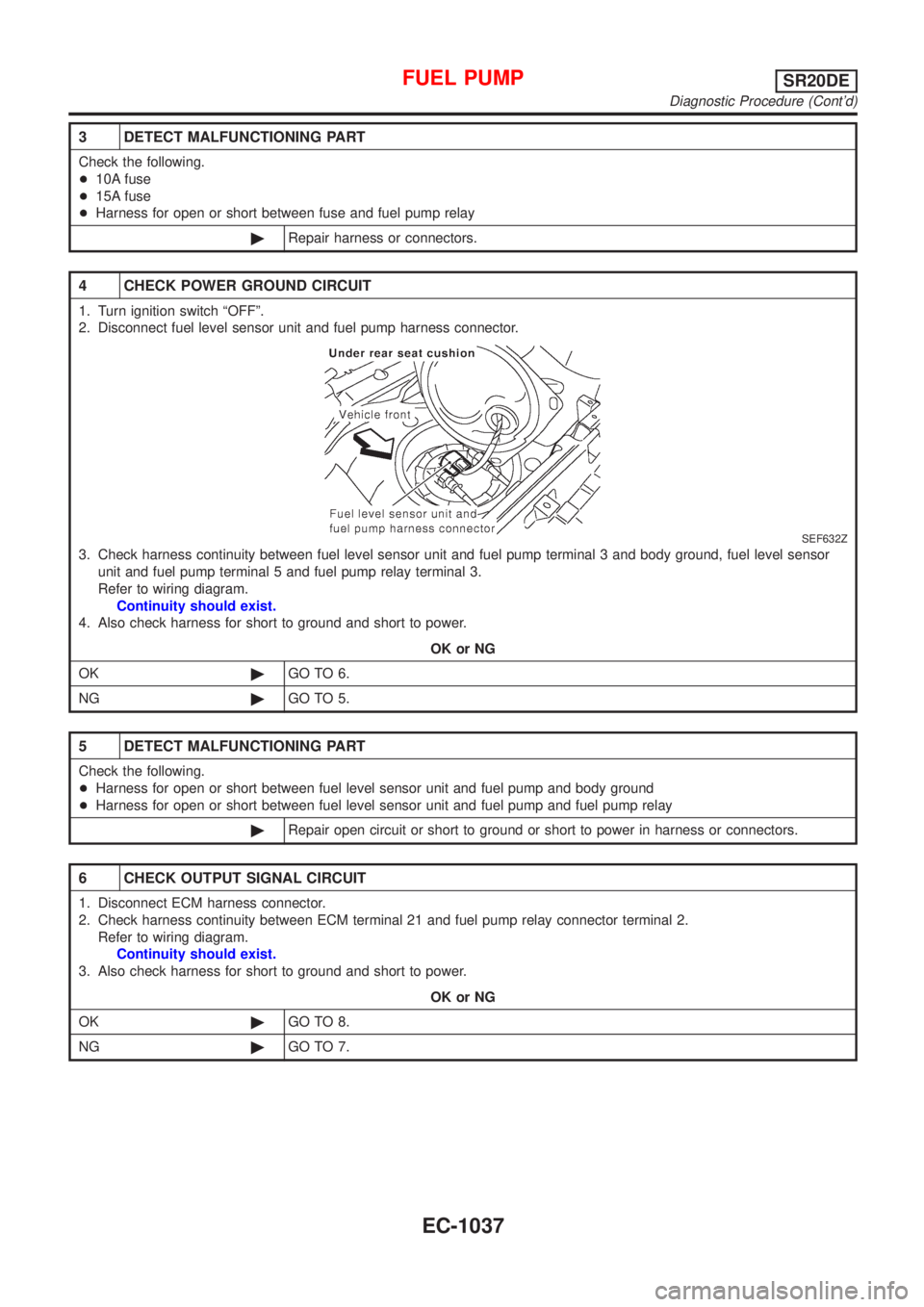
4 CHECK POWER GROUND CIRCUIT
1. Turn ignition switch ªOFFº.
2. Disconnect fuel level sensor unit and fuel pump harness connector.
SEF632Z
3. Check harness continuity between fuel level sensor unit and fuel pump terminal 3 and body ground, fuel level sensor
unit and fuel pump terminal 5 and fuel pump relay terminal 3.
Refer to wiring diagram.
Continuity should exist.
4. Also check harness for short to ground and short to power.
OK or NG
OK©GO TO 6.
NG©GO TO 5.
5 DETECT MALFUNCTIONING PART
Check the following.
+Harness for open or short between fuel level sensor unit and fuel pump and body ground
+Harness for open or short between fuel level sensor unit and fuel pump and fuel pump relay
©Repair open circuit or short to ground or short to power in harness or connectors.
6 CHECK OUTPUT SIGNAL CIRCUIT
1. Disconnect ECM harness connector.
2. Check harness continuity between ECM terminal 21 and fuel pump relay connector terminal 2.
Refer to wiring diagram.
Continuity should exist.
3. Also check harness for short to ground and short to power.
OK or NG
OK©GO TO 8.
NG©GO TO 7.
FUEL PUMPSR20DE
Diagnostic Procedure (Cont'd)
EC-1037
Page 1465 of 3051
Wiring DiagramNLEC1875
YEC715
POWER STEERING OIL PRESSURE SWITCHSR20DE
Wiring Diagram
EC-1040