Page 1432 of 3051
MODELS WITH ECM IN CABINNLEC1927S02
YEC938
IGNITION SIGNALSR20DE
Wiring Diagram (Cont'd)
EC-1007
Page 1434 of 3051

4 CHECK GROUND CIRCUIT
1. Turn ignition switch ªOFFº.
2. Disconnect camshaft position sensor harness connector.
3. Check harness continuity between CMPS terminal 5 and engine ground.
Refer to ªWiring Diagramº, EC-1006.
Continuity should exist.
4. Also check harness for short to power.
OK or NG
OK©GO TO 5.
NG©Repair open circuit or short to power in harness or connectors.
5 CHECK INPUT SIGNAL CIRCUIT-I
1. Disconnect ECM harness connector.
2. Check harness continuity between ECM terminal 35 and CMPS terminal 6.
Refer to ªWiring Diagramº, EC-1006.
Continuity should exist.
3. Also check harness for short to ground and short to power.
OK or NG
OK©GO TO 6.
NG©Repair open circuit or short to ground or short to power in harness or connectors.
6 CHECK IGNITION COIL, POWER TRANSISTOR
Refer to ªComponent Inspectionº, EC-1010.
OK or NG
OK©GO TO 7.
NG©Replace malfunctioning component(s).
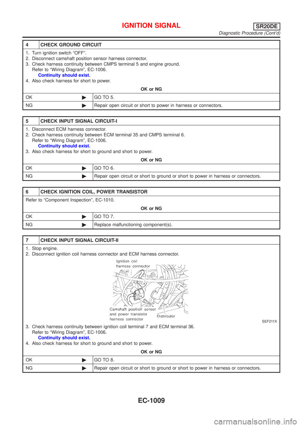
7 CHECK INPUT SIGNAL CIRCUIT-II
1. Stop engine.
2. Disconnect ignition coil harness connector and ECM harness connector.
SEF211X
3. Check harness continuity between ignition coil terminal 7 and ECM terminal 36.
Refer to ªWiring Diagramº, EC-1006.
Continuity should exist.
4. Also check harness for short to ground and short to power.
OK or NG
OK©GO TO 8.
NG©Repair open circuit or short to ground or short to power in harness or connectors.
IGNITION SIGNALSR20DE
Diagnostic Procedure (Cont'd)
EC-1009
Page 1438 of 3051
Wiring Diagram=NLEC1845
YEC719
A/T COMMUNICATION LINESR20DE
Wiring Diagram
EC-1013
Page 1439 of 3051
Diagnostic ProcedureNLEC1846
1 CHECK OVERALL FUNCTION
1. Start engine and warm it up to normal operating temperature.
2. Check the voltage between ECM terminals 10, 19, 54, 55, 56 and ground.
SEF791Z
OK or NG
OK©INSPECTION END
NG©GO TO 2.
2 CHECK A/T CONTROL INPUT SIGNAL CIRCUIT FOR OPEN
1. Turn ignition switch ªOFFº.
2. Disconnect ECM harness connector and TCM (Transmission Control Module) harness connector.
SEF116Y
3. Check harness continuity between the following terminals.
MTBL0574
Refer to Wiring Diagram.
Continuity should exist.
OK or NG
OK©GO TO 3.
NG©Repair harness or connectors.
A/T COMMUNICATION LINESR20DE
Diagnostic Procedure
EC-1014
Page 1440 of 3051
3 CHECK A/T CONTROL INPUT SIGNAL CIRCUIT FOR SHORT
1. Check harness continuity between ECM terminals 10, 19, 54, 55, 56 and ground.
Refer to Wiring Diagram.
Continuity should not exist.
2. Also check harness for short to power.
OK or NG
OK©GO TO 4.
NG©Repair short to ground or short to power in harness or connectos.
4 CHECK INTERMITTENT INCIDENT
Refer to ªTROUBLE DIAGNOSIS FOR INTERMITTENT INCIDENTº, EC-670.
©INSPECTION END
A/T COMMUNICATION LINESR20DE
Diagnostic Procedure (Cont'd)
EC-1015
Page 1442 of 3051
Wiring DiagramNLEC1853TYPE-1NLEC1853S01
YEC760
PARK/NEUTRAL POSITION (PNP) SWITCHSR20DE
Wiring Diagram
EC-1017
Page 1443 of 3051
TYPE-2NLEC1853S02
YEC939
PARK/NEUTRAL POSITION (PNP) SWITCHSR20DE
Wiring Diagram (Cont'd)
EC-1018
Page 1447 of 3051
Wiring DiagramNLEC1858MODELS WITH ECM IN ENGINE COMPARTMENTNLEC1858S01
YEC711
INJECTORSR20DE
Wiring Diagram
EC-1022