Page 1304 of 3051

8) If it is impossible to adjust closed throttle position switch in
ªBasic Inspectionº, replace closed throttle position switch.
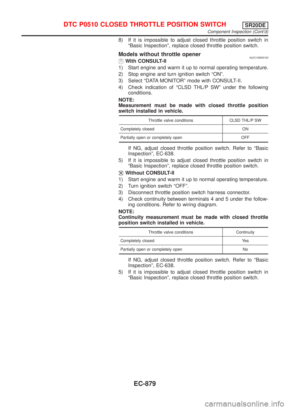
Models without throttle openerNLEC1595S0102With CONSULT-II
1) Start engine and warm it up to normal operating temperature.
2) Stop engine and turn ignition switch ªONº.
3) Select ªDATA MONITORº mode with CONSULT-II.
4) Check indication of ªCLSD THL/P SWº under the following
conditions.
NOTE:
Measurement must be made with closed throttle position
switch installed in vehicle.
Throttle valve conditions CLSD THL/P SW
Completely closed ON
Partially open or completely open OFF
If NG, adjust closed throttle position switch. Refer to ªBasic
Inspectionº, EC-638.
5) If it is impossible to adjust closed throttle position switch in
ªBasic Inspectionº, replace closed throttle position switch.
Without CONSULT-II
1) Start engine and warm it up to normal operating temperature.
2) Turn ignition switch ªOFFº.
3) Disconnect throttle position switch harness connector.
4) Check continuity between terminals 4 and 5 under the follow-
ing conditions. Refer to wiring diagram.
NOTE:
Continuity measurement must be made with closed throttle
position switch installed in vehicle.
Throttle valve conditions Continuity
Completely closed Yes
Partially open or completely open No
If NG, adjust closed throttle position switch. Refer to ªBasic
Inspectionº, EC-638.
5) If it is impossible to adjust closed throttle position switch in
ªBasic Inspectionº, replace closed throttle position switch.
DTC P0510 CLOSED THROTTLE POSITION SWITCHSR20DE
Component Inspection (Cont'd)
EC-879
Page 1310 of 3051
Wiring DiagramNLEC1623MODELS WITH FUSE AND FUSIBLE LINK BOX E43NLEC1623S03
YEC706
DTC P1217 OVERHEAT (COOLING SYSTEM)SR20DE
Wiring Diagram
EC-885
Page 1311 of 3051
MODELS WITH FUSE AND FUSIBLE LINK BOX E90NLEC1623S04
YEC927
DTC P1217 OVERHEAT (COOLING SYSTEM)SR20DE
Wiring Diagram (Cont'd)
EC-886
Page 1317 of 3051

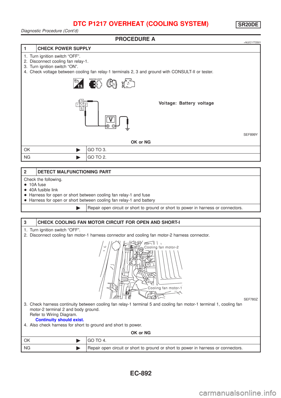
PROCEDURE A=NLEC1772S01
1 CHECK POWER SUPPLY
1. Turn ignition switch ªOFFº.
2. Disconnect cooling fan relay-1.
3. Turn ignition switch ªONº.
4. Check voltage between cooling fan relay-1 terminals 2, 3 and ground with CONSULT-II or tester.
SEF899Y
OK or NG
OK©GO TO 3.
NG©GO TO 2.
2 DETECT MALFUNCTIONING PART
Check the following.
+10A fuse
+40A fusible link
+Harness for open or short between cooling fan relay-1 and fuse
+Harness for open or short between cooling fan relay-1 and battery
©Repair open circuit or short to ground or short to power in harness or connectors.
3 CHECK COOLING FAN MOTOR CIRCUIT FOR OPEN AND SHORT-I
1. Turn ignition switch ªOFFº.
2. Disconnect cooling fan motor-1 harness connector and cooling fan motor-2 harness connector.
SEF780Z
3. Check harness continuity between cooling fan relay-1 terminal 5 and cooling fan motor-1 terminal 1, cooling fan
motor-2 terminal 2 and body ground.
Refer to Wiring Diagram.
Continuity should exist.
4. Also check harness for short to ground and short to power.
OK or NG
OK©GO TO 4.
NG©Repair open circuit or short to ground or short to power in harness or connectors.
DTC P1217 OVERHEAT (COOLING SYSTEM)SR20DE
Diagnostic Procedure (Cont'd)
EC-892
Page 1318 of 3051

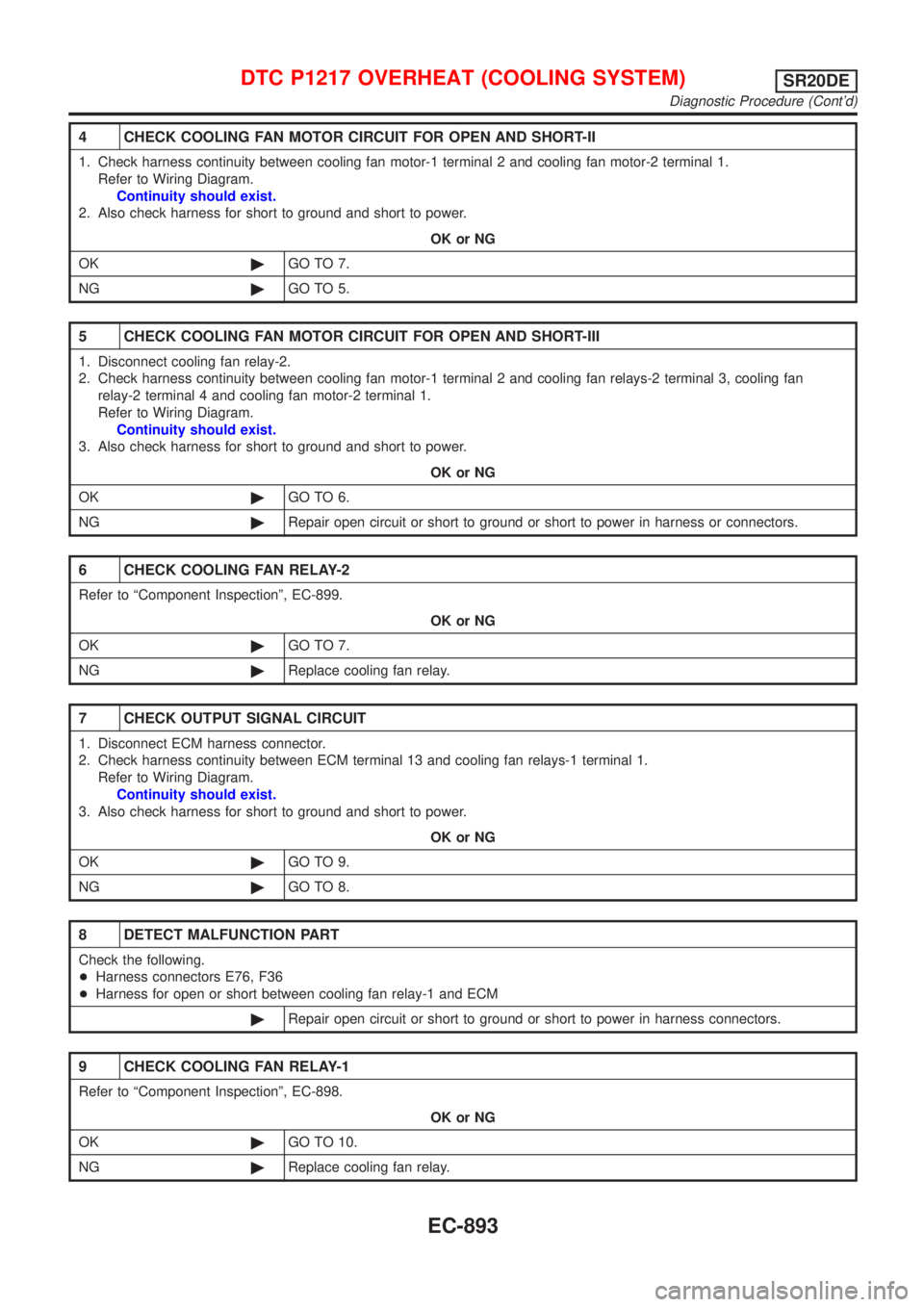
4 CHECK COOLING FAN MOTOR CIRCUIT FOR OPEN AND SHORT-II
1. Check harness continuity between cooling fan motor-1 terminal 2 and cooling fan motor-2 terminal 1.
Refer to Wiring Diagram.
Continuity should exist.
2. Also check harness for short to ground and short to power.
OK or NG
OK©GO TO 7.
NG©GO TO 5.
5 CHECK COOLING FAN MOTOR CIRCUIT FOR OPEN AND SHORT-III
1. Disconnect cooling fan relay-2.
2. Check harness continuity between cooling fan motor-1 terminal 2 and cooling fan relays-2 terminal 3, cooling fan
relay-2 terminal 4 and cooling fan motor-2 terminal 1.
Refer to Wiring Diagram.
Continuity should exist.
3. Also check harness for short to ground and short to power.
OK or NG
OK©GO TO 6.
NG©Repair open circuit or short to ground or short to power in harness or connectors.
6 CHECK COOLING FAN RELAY-2
Refer to ªComponent Inspectionº, EC-899.
OK or NG
OK©GO TO 7.
NG©Replace cooling fan relay.
7 CHECK OUTPUT SIGNAL CIRCUIT
1. Disconnect ECM harness connector.
2. Check harness continuity between ECM terminal 13 and cooling fan relays-1 terminal 1.
Refer to Wiring Diagram.
Continuity should exist.
3. Also check harness for short to ground and short to power.
OK or NG
OK©GO TO 9.
NG©GO TO 8.
8 DETECT MALFUNCTION PART
Check the following.
+Harness connectors E76, F36
+Harness for open or short between cooling fan relay-1 and ECM
©Repair open circuit or short to ground or short to power in harness connectors.
9 CHECK COOLING FAN RELAY-1
Refer to ªComponent Inspectionº, EC-898.
OK or NG
OK©GO TO 10.
NG©Replace cooling fan relay.
DTC P1217 OVERHEAT (COOLING SYSTEM)SR20DE
Diagnostic Procedure (Cont'd)
EC-893
Page 1321 of 3051

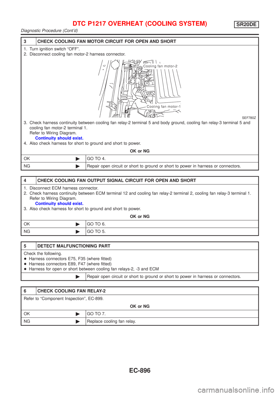
3 CHECK COOLING FAN MOTOR CIRCUIT FOR OPEN AND SHORT
1. Turn ignition switch ªOFFº.
2. Disconnect cooling fan motor-2 harness connector.
SEF780Z
3. Check harness continuity between cooling fan relay-2 terminal 5 and body ground, cooling fan relay-3 terminal 5 and
cooling fan motor-2 terminal 1.
Refer to Wiring Diagram.
Continuity should exist.
4. Also check harness for short to ground and short to power.
OK or NG
OK©GO TO 4.
NG©Repair open circuit or short to ground or short to power in harness or connectors.
4 CHECK COOLING FAN OUTPUT SIGNAL CIRCUIT FOR OPEN AND SHORT
1. Disconnect ECM harness connector.
2. Check harness continuity between ECM terminal 12 and cooling fan relay-2 terminal 2, cooling fan relay-3 terminal 1.
Refer to Wiring Diagram.
Continuity should exist.
3. Also check harness for short to ground and short to power.
OK or NG
OK©GO TO 6.
NG©GO TO 5.
5 DETECT MALFUNCTIONING PART
Check the following.
+Harness connectors E75, F35 (where fitted)
+Harness connectors E89, F47 (where fitted)
+Harness for open or short between cooling fan relays-2, -3 and ECM
©Repair open circuit or short to ground or short to power in harness or connectors.
6 CHECK COOLING FAN RELAY-2
Refer to ªComponent Inspectionº, EC-899.
OK or NG
OK©GO TO 7.
NG©Replace cooling fan relay.
DTC P1217 OVERHEAT (COOLING SYSTEM)SR20DE
Diagnostic Procedure (Cont'd)
EC-896
Page 1328 of 3051
Wiring DiagramNLEC1914MODELS WITH ECM IN ENGINE COMPARTMENTNLEC1914S01
YEC712
DTC P1320 IGNITION SIGNALSR20DE
Wiring Diagram
EC-903
Page 1329 of 3051
MODELS WITH ECM IN CABINNLEC1914S02
YEC928
DTC P1320 IGNITION SIGNALSR20DE
Wiring Diagram (Cont'd)
EC-904