Page 1286 of 3051
MODELS WITH ECM IN CABINNLEC1577S04
YEC924
DTC P0500 VEHICLE SPEED SENSOR (VSS)SR20DE
Wiring Diagram (Cont'd)
EC-861
Page 1290 of 3051
Wiring DiagramNLEC1584MODELS WITH ECM IN ENGINE COMPARTMENTNLEC1584S01
YEC704
DTC P0505 IDLE AIR CONTROL VALVE (IACV) Ð AUXILIARY AIR CONTROL
(AAC) VALVE
SR20DE
Wiring Diagram
EC-865
Page 1291 of 3051
MODELS WITH ECM IN CABINNLEC1584S02
YEC925
DTC P0505 IDLE AIR CONTROL VALVE (IACV) Ð AUXILIARY AIR CONTROL
(AAC) VALVE
SR20DE
Wiring Diagram (Cont'd)
EC-866
Page 1292 of 3051

Diagnostic ProcedureNLEC1585
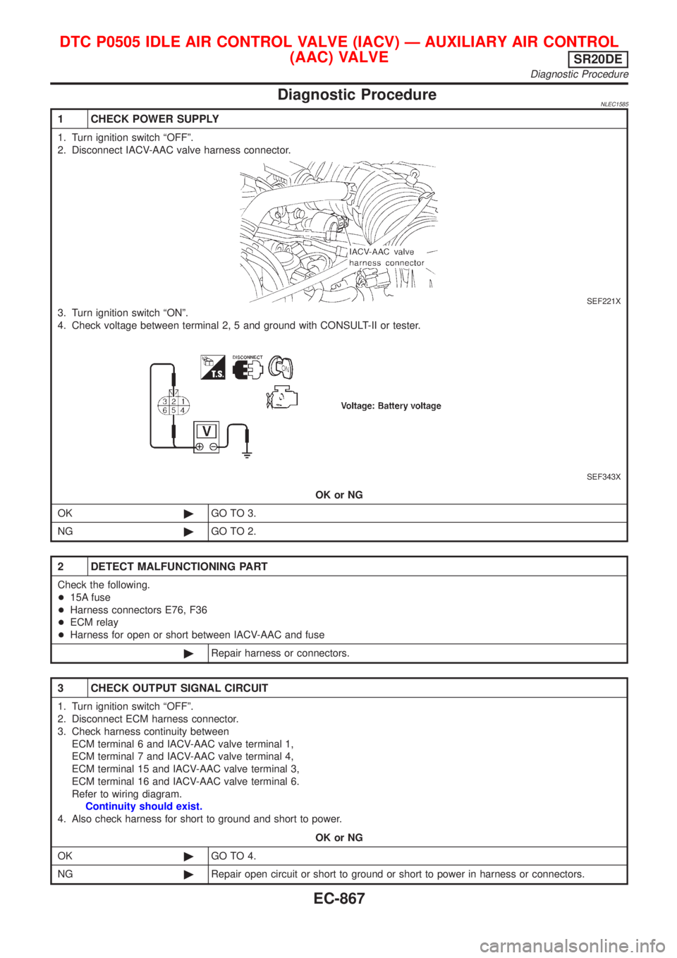
1 CHECK POWER SUPPLY
1. Turn ignition switch ªOFFº.
2. Disconnect IACV-AAC valve harness connector.
SEF221X
3. Turn ignition switch ªONº.
4. Check voltage between terminal 2, 5 and ground with CONSULT-II or tester.
SEF343X
OK or NG
OK©GO TO 3.
NG©GO TO 2.
2 DETECT MALFUNCTIONING PART
Check the following.
+15A fuse
+Harness connectors E76, F36
+ECM relay
+Harness for open or short between IACV-AAC and fuse
©Repair harness or connectors.
3 CHECK OUTPUT SIGNAL CIRCUIT
1. Turn ignition switch ªOFFº.
2. Disconnect ECM harness connector.
3. Check harness continuity between
ECM terminal 6 and IACV-AAC valve terminal 1,
ECM terminal 7 and IACV-AAC valve terminal 4,
ECM terminal 15 and IACV-AAC valve terminal 3,
ECM terminal 16 and IACV-AAC valve terminal 6.
Refer to wiring diagram.
Continuity should exist.
4. Also check harness for short to ground and short to power.
OK or NG
OK©GO TO 4.
NG©Repair open circuit or short to ground or short to power in harness or connectors.
DTC P0505 IDLE AIR CONTROL VALVE (IACV) Ð AUXILIARY AIR CONTROL
(AAC) VALVE
SR20DE
Diagnostic Procedure
EC-867
Page 1299 of 3051
Wiring DiagramNLEC1593MODELS WITH ECM IN ENGINE COMPARTMENTNLEC1593S01
YEC705
DTC P0510 CLOSED THROTTLE POSITION SWITCHSR20DE
Wiring Diagram
EC-874
Page 1300 of 3051
MODELS WITH ECM IN CABINNLEC1593S02
YEC926
DTC P0510 CLOSED THROTTLE POSITION SWITCHSR20DE
Wiring Diagram (Cont'd)
EC-875
Page 1301 of 3051
Diagnostic ProcedureNLEC1594
1 CHECK POWER SUPPLY
1. Turn ignition switch ªOFFº.
2. Disconnect throttle position switch harness connector.
SEF770Z
3. Turn ignition switch ªONº.
4. Check voltage between throttle position switch terminal 5 and engine ground with CONSULT-II or tester.
SEF346X
OK or NG
OK©GO TO 3.
NG©GO TO 2.
2 DETECT MALFUNCTIONING PART
Check the following.
+Harness connectors E76, F36
+15A fuse
+ECM relay
+Harness for open or short between throttle position switch and fuse
©Repair harness or connectors.
3 CHECK INPUT SIGNAL CIRCUIT
1. Turn ignition switch ªOFFº.
2. Disconnect ECM harness connector.
3. Check harness continuity between ECM terminal 40 and throttle position switch terminal 4.
Refer to wiring diagram.
Continuity should exist.
4. Also check harness for short to ground and short to power.
OK or NG
OK©GO TO 5.
NG©GO TO 4.
DTC P0510 CLOSED THROTTLE POSITION SWITCHSR20DE
Diagnostic Procedure
EC-876
Page 1303 of 3051

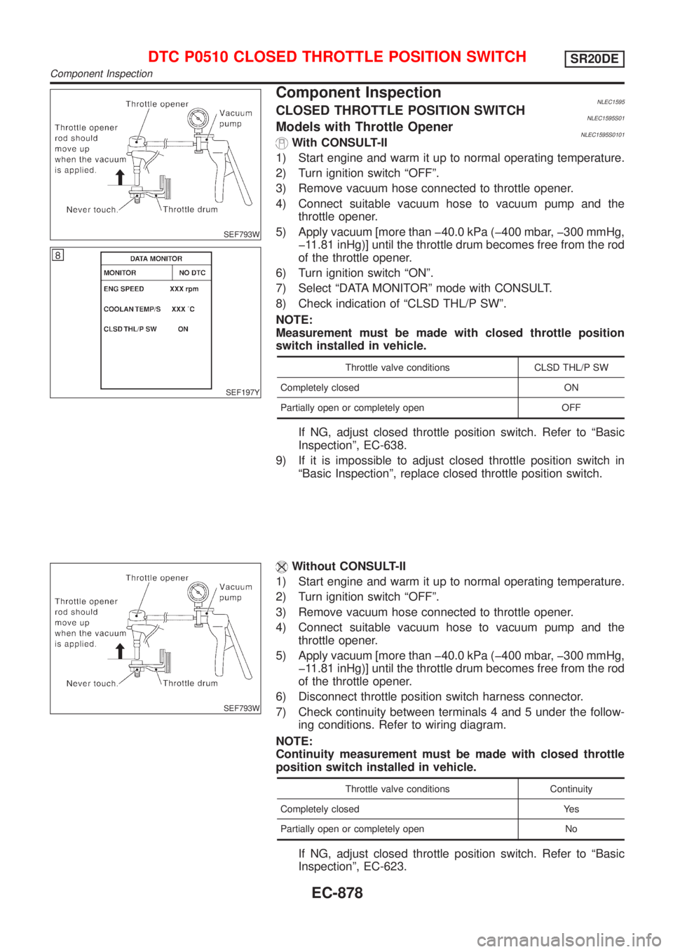
SEF793W
SEF197Y
Component InspectionNLEC1595CLOSED THROTTLE POSITION SWITCHNLEC1595S01Models with Throttle OpenerNLEC1595S0101With CONSULT-II
1) Start engine and warm it up to normal operating temperature.
2) Turn ignition switch ªOFFº.
3) Remove vacuum hose connected to throttle opener.
4) Connect suitable vacuum hose to vacuum pump and the
throttle opener.
5) Apply vacuum [more than þ40.0 kPa (þ400 mbar, þ300 mmHg,
þ11.81 inHg)] until the throttle drum becomes free from the rod
of the throttle opener.
6) Turn ignition switch ªONº.
7) Select ªDATA MONITORº mode with CONSULT.
8) Check indication of ªCLSD THL/P SWº.
NOTE:
Measurement must be made with closed throttle position
switch installed in vehicle.
Throttle valve conditions CLSD THL/P SW
Completely closed ON
Partially open or completely open OFF
If NG, adjust closed throttle position switch. Refer to ªBasic
Inspectionº, EC-638.
9) If it is impossible to adjust closed throttle position switch in
ªBasic Inspectionº, replace closed throttle position switch.
SEF793W
Without CONSULT-II
1) Start engine and warm it up to normal operating temperature.
2) Turn ignition switch ªOFFº.
3) Remove vacuum hose connected to throttle opener.
4) Connect suitable vacuum hose to vacuum pump and the
throttle opener.
5) Apply vacuum [more than þ40.0 kPa (þ400 mbar, þ300 mmHg,
þ11.81 inHg)] until the throttle drum becomes free from the rod
of the throttle opener.
6) Disconnect throttle position switch harness connector.
7) Check continuity between terminals 4 and 5 under the follow-
ing conditions. Refer to wiring diagram.
NOTE:
Continuity measurement must be made with closed throttle
position switch installed in vehicle.
Throttle valve conditions Continuity
Completely closed Yes
Partially open or completely open No
If NG, adjust closed throttle position switch. Refer to ªBasic
Inspectionº, EC-623.
DTC P0510 CLOSED THROTTLE POSITION SWITCHSR20DE
Component Inspection
EC-878