Page 934 of 3051

15 CHECK IGNITION COIL OUTPUT SIGNAL CIRCUIT
1. Disconnect ECM harness connector.
2. Check harness continuity between ECM terminals 35, 36, 37, 38 and ignition coil terminal 3. Refer to Wiring Diagram.
Continuity should exist.
3. Also check harness for short to ground and short to power.
OK or NG
OK©GO TO 16.
NG©Repair open circuit or short to ground or short to power in harness or connectors.
16 CHECK IGNITION COIL WITH POWER TRANSISTOR
Refer to ªComponent Inspectionº, EC-509.
OK or NG
OK©GO TO 17.
NG©Replace ignition coil with power transistor.
17 CHECK INTERMITTENT INCIDENT
Refer to ªTROUBLE DIAGNOSIS FOR INTERMITTENT INCIDENTº, EC-145.
©INSPECTION END
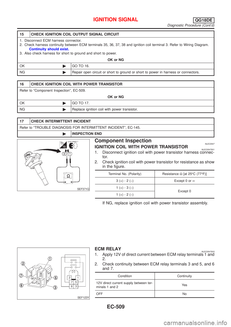
SEF371Q
Component InspectionNLEC0547IGNITION COIL WITH POWER TRANSISTORNLEC0547S011. Disconnect ignition coil with power transistor harness connec-
tor.
2. Check ignition coil with power transistor for resistance as show
in the figure.
Terminal No. (Polarity) ResistanceW[at 25ÉC (77ÉF)]
3 (+) - 2 (þ) Except 0 or¥
1 (+) - 3 (þ)
Except 0
1 (+) - 2 (þ)
If NG, replace ignition coil with power transistor assembly.
SEF123Y
ECM RELAYNLEC0547S031. Apply 12V of direct current between ECM relay terminals 1 and
2.
2. Check continuity between ECM relay terminals 3 and 5, and 6
and 7.
Condition Continuity
12V direct current supply between ter-
minals 1 and 2Ye s
OFF No
IGNITION SIGNALQG18DE
Diagnostic Procedure (Cont'd)
EC-509
Page 937 of 3051
Wiring DiagramNLEC0440MODELS WITH ECM IN ENGINE COMPARTMENTNLEC0440S01
YEC675
START SIGNALQG18DE
Wiring Diagram
EC-512
Page 938 of 3051
MODELS WITH ECM IN CABINNLEC0440S02
YEC903
START SIGNALQG18DE
Wiring Diagram (Cont'd)
EC-513
Page 943 of 3051
Wiring DiagramNLEC0447MODELS WITH ECM IN ENGINE COMPARTMENTNLEC0447S01
YEC714
FUEL PUMPQG18DE
Wiring Diagram
EC-518
Page 944 of 3051
MODELS WITH ECM IN CABINNLEC0447S02
YEC904
FUEL PUMPQG18DE
Wiring Diagram (Cont'd)
EC-519
Page 946 of 3051

3 DETECT MALFUNCTIONING PART
Check the following.
+10A fuse
+15A fuse
+Harness for open or short between fuse and fuel pump relay
©Repair harness or connectors.
4 CHECK POWER GROUND CIRCUIT
1. Turn ignition switch ªOFFº.
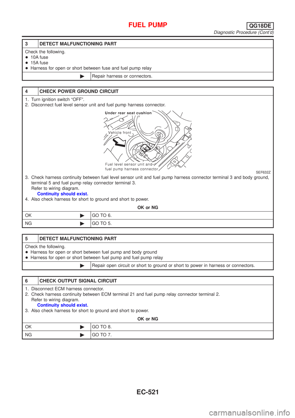
2. Disconnect fuel level sensor unit and fuel pump harness connector.
SEF632Z
3. Check harness continuity between fuel level sensor unit and fuel pump harness connector terminal 3 and body ground,
terminal 5 and fuel pump relay connector terminal 3.
Refer to wiring diagram.
Continuity should exist.
4. Also check harness for short to ground and short to power.
OK or NG
OK©GO TO 6.
NG©GO TO 5.
5 DETECT MALFUNCTIONING PART
Check the following.
+Harness for open or short between fuel pump and body ground
+Harness for open or short between fuel pump and fuel pump relay
©Repair open circuit or short to ground or short to power in harness or connectors.
6 CHECK OUTPUT SIGNAL CIRCUIT
1. Disconnect ECM harness connector.
2. Check harness continuity between ECM terminal 21 and fuel pump relay connector terminal 2.
Refer to wiring diagram.
Continuity should exist.
3. Also check harness for short to ground and short to power.
OK or NG
OK©GO TO 8.
NG©GO TO 7.
FUEL PUMPQG18DE
Diagnostic Procedure (Cont'd)
EC-521
Page 949 of 3051
Wiring DiagramNLEC0450MODELS WITH ECM IN ENGINE COMPARTMENTNLEC0450S01
YEC658
POWER STEERING OIL PRESSURE SWITCHQG18DE
Wiring Diagram
EC-524
Page 950 of 3051
MODELS WITH ECM IN CABINNLEC0450S02
YEC905
POWER STEERING OIL PRESSURE SWITCHQG18DE
Wiring Diagram (Cont'd)
EC-525