Page 902 of 3051
MODELS WITH ECM IN CABINNLEC1319S02
YEC900
INTAKE VALVE TIMING CONTROL SOLENOID VALVEQG18DE
Wiring Diagram (Cont'd)
EC-477
Page 904 of 3051

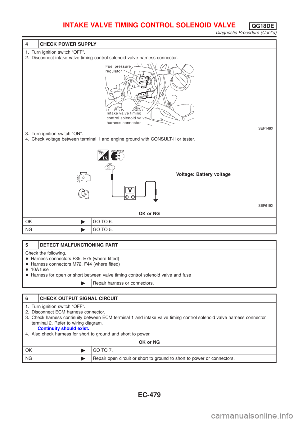
4 CHECK POWER SUPPLY
1. Turn ignition switch ªOFFº.
2. Disconnect intake valve timing control solenoid valve harness connector.
SEF149X
3. Turn ignition switch ªONº.
4. Check voltage between terminal 1 and engine ground with CONSULT-II or tester.
SEF619X
OK or NG
OK©GO TO 6.
NG©GO TO 5.
5 DETECT MALFUNCTIONING PART
Check the following.
+Harness connectors F35, E75 (where fitted)
+Harness connectors M72, F44 (where fitted)
+10A fuse
+Harness for open or short between valve timing control solenoid valve and fuse
©Repair harness or connectors.
6 CHECK OUTPUT SIGNAL CIRCUIT
1. Turn ignition switch ªOFFº.
2. Disconnect ECM harness connector.
3. Check harness continuity between ECM terminal 1 and intake valve timing control solenoid valve harness connector
terminal 2. Refer to wiring diagram.
Continuity should exist.
4. Also check harness for short to ground and short to power.
OK or NG
OK©GO TO 7.
NG©Repair open circuit or short to ground to short to power or connectors.
INTAKE VALVE TIMING CONTROL SOLENOID VALVEQG18DE
Diagnostic Procedure (Cont'd)
EC-479
Page 908 of 3051
Wiring DiagramNLEC1254
YEC661
SWIRL CONTROL VALVE CONTROL SYSTEM
(WHERE FITTED)
QG18DE
Wiring Diagram
EC-483
Page 912 of 3051

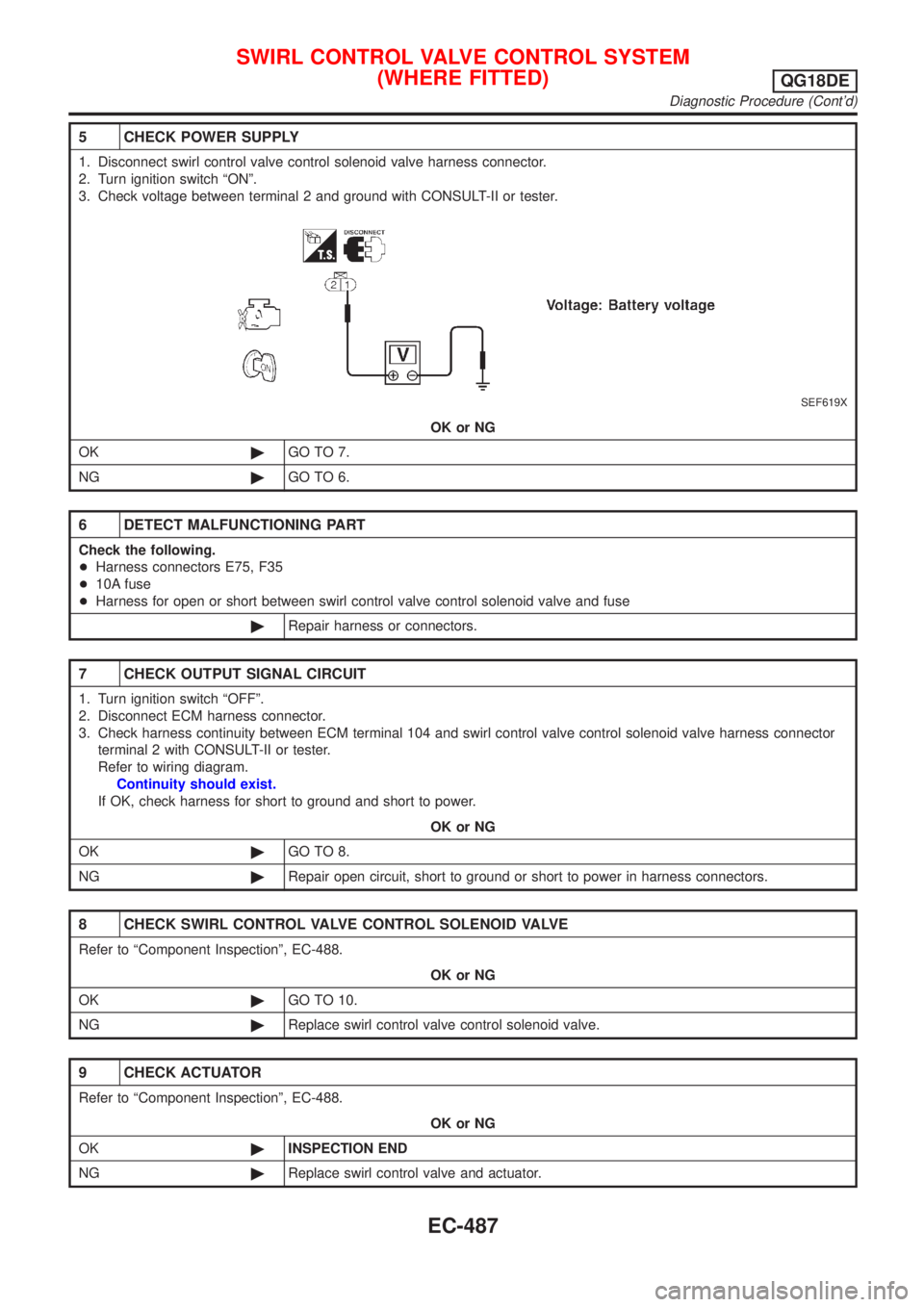
5 CHECK POWER SUPPLY
1. Disconnect swirl control valve control solenoid valve harness connector.
2. Turn ignition switch ªONº.
3. Check voltage between terminal 2 and ground with CONSULT-II or tester.
SEF619X
OK or NG
OK©GO TO 7.
NG©GO TO 6.
6 DETECT MALFUNCTIONING PART
Check the following.
+Harness connectors E75, F35
+10A fuse
+Harness for open or short between swirl control valve control solenoid valve and fuse
©Repair harness or connectors.
7 CHECK OUTPUT SIGNAL CIRCUIT
1. Turn ignition switch ªOFFº.
2. Disconnect ECM harness connector.
3. Check harness continuity between ECM terminal 104 and swirl control valve control solenoid valve harness connector
terminal 2 with CONSULT-II or tester.
Refer to wiring diagram.
Continuity should exist.
If OK, check harness for short to ground and short to power.
OK or NG
OK©GO TO 8.
NG©Repair open circuit, short to ground or short to power in harness connectors.
8 CHECK SWIRL CONTROL VALVE CONTROL SOLENOID VALVE
Refer to ªComponent Inspectionº, EC-488.
OK or NG
OK©GO TO 10.
NG©Replace swirl control valve control solenoid valve.
9 CHECK ACTUATOR
Refer to ªComponent Inspectionº, EC-488.
OK or NG
OK©INSPECTION END
NG©Replace swirl control valve and actuator.
SWIRL CONTROL VALVE CONTROL SYSTEM
(WHERE FITTED)
QG18DE
Diagnostic Procedure (Cont'd)
EC-487
Page 916 of 3051
Wiring DiagramNLEC1328
YEC753
PARK/NEUTRAL POSITION (PNP) SWITCHQG18DE
Wiring Diagram
EC-491
Page 918 of 3051

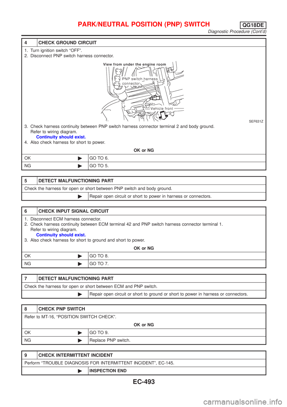
4 CHECK GROUND CIRCUIT
1. Turn ignition switch ªOFFº.
2. Disconnect PNP switch harness connector.
SEF631Z
3. Check harness continuity between PNP switch harness connector terminal 2 and body ground.
Refer to wiring diagram.
Continuity should exist.
4. Also check harness for short to power.
OK or NG
OK©GO TO 6.
NG©GO TO 5.
5 DETECT MALFUNCTIONING PART
Check the harness for open or short between PNP switch and body ground.
©Repair open circuit or short to power in harness or connectors.
6 CHECK INPUT SIGNAL CIRCUIT
1. Disconnect ECM harness connector.
2. Check harness continuity between ECM terminal 42 and PNP switch harness connector terminal 1.
Refer to wiring diagram.
Continuity should exist.
3. Also check harness for short to ground and short to power.
OK or NG
OK©GO TO 8.
NG©GO TO 7.
7 DETECT MALFUNCTIONING PART
Check the harness for open or short between ECM and PNP switch.
©Repair open circuit or short to ground or short to power in harness or connectors.
8 CHECK PNP SWITCH
Refer to MT-16, ªPOSITION SWITCH CHECKº.
OK or NG
OK©GO TO 9.
NG©Replace PNP switch.
9 CHECK INTERMITTENT INCIDENT
Perform ªTROUBLE DIAGNOSIS FOR INTERMITTENT INCIDENTº, EC-145.
©INSPECTION END
PARK/NEUTRAL POSITION (PNP) SWITCHQG18DE
Diagnostic Procedure (Cont'd)
EC-493
Page 920 of 3051
Wiring DiagramNLEC0434MODELS WITH ECM IN ENGINE COMPARTMENTNLEC0434S01
YEC672
INJECTORQG18DE
Wiring Diagram
EC-495
Page 921 of 3051
MODELS WITH ECM IN CABINNLEC0434S02
YEC901
INJECTORQG18DE
Wiring Diagram (Cont'd)
EC-496