Page 829 of 3051
Wiring DiagramNLEC0430
YEC671
DTC P1706 PARK/NEUTRAL POSITION (PNP) SWITCHQG18DE
Wiring Diagram
EC-404
Page 830 of 3051

Diagnostic ProcedureNLEC0431
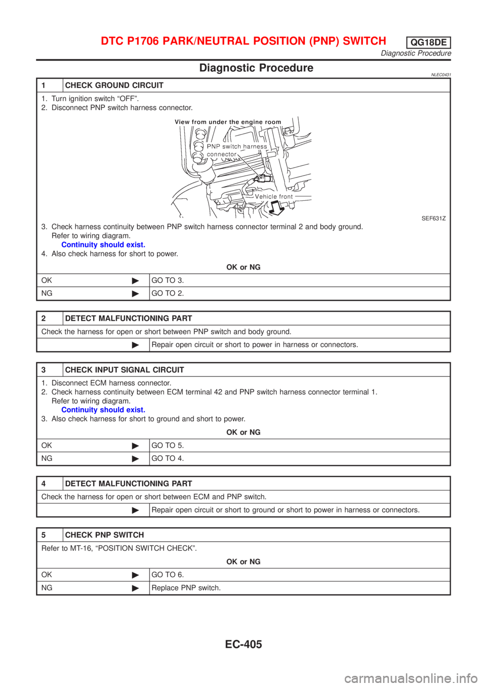
1 CHECK GROUND CIRCUIT
1. Turn ignition switch ªOFFº.
2. Disconnect PNP switch harness connector.
SEF631Z
3. Check harness continuity between PNP switch harness connector terminal 2 and body ground.
Refer to wiring diagram.
Continuity should exist.
4. Also check harness for short to power.
OK or NG
OK©GO TO 3.
NG©GO TO 2.
2 DETECT MALFUNCTIONING PART
Check the harness for open or short between PNP switch and body ground.
©Repair open circuit or short to power in harness or connectors.
3 CHECK INPUT SIGNAL CIRCUIT
1. Disconnect ECM harness connector.
2. Check harness continuity between ECM terminal 42 and PNP switch harness connector terminal 1.
Refer to wiring diagram.
Continuity should exist.
3. Also check harness for short to ground and short to power.
OK or NG
OK©GO TO 5.
NG©GO TO 4.
4 DETECT MALFUNCTIONING PART
Check the harness for open or short between ECM and PNP switch.
©Repair open circuit or short to ground or short to power in harness or connectors.
5 CHECK PNP SWITCH
Refer to MT-16, ªPOSITION SWITCH CHECKº.
OK or NG
OK©GO TO 6.
NG©Replace PNP switch.
DTC P1706 PARK/NEUTRAL POSITION (PNP) SWITCHQG18DE
Diagnostic Procedure
EC-405
Page 834 of 3051
Wiring DiagramNLEC1278MODELS WITH INTAKE AIR TEMPERATURE SENSOR
ON INTAKE AIR DUCT
NLEC1278S01
YEC749
INTAKE AIR TEMPERATURE SENSORQG18DE
Wiring Diagram
EC-409
Page 835 of 3051
MODELS WITH INTAKE AIR TEMPERATURE SENSOR
IN MASS AIR FLOW SENSOR
NLEC1278S02
YEC892
INTAKE AIR TEMPERATURE SENSORQG18DE
Wiring Diagram (Cont'd)
EC-410
Page 837 of 3051
3 CHECK POWER SUPPLY (Models with intake air temperature in mass air flow sensor)
1. Turn ignition switch ªOFFº.
2. Disconnect intake air temperature sensor (mass air flow sensor) harness connector.
NEF306A
3. Turn ignition switch ªONº.
4. Check voltage between terminal 5 and ground with CONSULT-II or tester.
NEF307A
OK or NG
OK©GO TO 5.
NG©GO TO 4.
4 DETECT MALFUNCTIONING PART
Check the following.
+Harness connectors E75, F35 (where fitted)
+Harness for open or short between ECM and intake air temperature sensor
©Repair harness or connectors.
5 CHECK GROUND CIRCUIT
1. Turn ignition switch ªOFFº.
2. Check harness continuity between intake air temperature sensor harness connector and engine ground.
Refer to wiring diagram.
Continuity should exist.
3. Also check harness for short to power.
OK or NG
OK©GO TO 7.
NG©GO TO 6.
INTAKE AIR TEMPERATURE SENSORQG18DE
Diagnostic Procedure (Cont'd)
EC-412
Page 840 of 3051
Wiring DiagramNLEC1220MODELS WITH ECM IN ENGINE COMPARTMENTNLEC1220S03
YEC676
HEATED OXYGEN SENSOR 1 (FRONT)QG18DE
Wiring Diagram
EC-415
Page 841 of 3051
MODELS WITH ECM IN CABINNLEC1220S04
YEC893
HEATED OXYGEN SENSOR 1 (FRONT)QG18DE
Wiring Diagram (Cont'd)
EC-416
Page 843 of 3051
4 RETIGHTEN GROUND SCREWS
1. Turn ignition switch ªOFFº.
2. Loosen and retighten engine ground screws.
JEF104Y
3. Disconnect heated oxygen sensor 1 (front) harness connector.
SEF012XA
©GO TO 5.
5 RETIGHTEN HEATED OXYGEN SENSOR 1 (FRONT)
Loosen and retighten corresponding heated oxygen sensor 1 (front).
Tightening torque:
40 - 50 N´m (4.1 - 5.1 kg-m, 30 - 37 ft-lb)
©GO TO 6.
6 CHECK INPUT SIGNAL CIRCUIT
1. Disconnect ECM harness connector.
2. Check harness continuity between ECM terminal 62 and heated oxygen sensor 1 (front) harness connector terminal 2.
Refer to wiring diagram.
Continuity should exist.
3. Check harness continuity between ECM terminal 62 (or terminal 2) and ground.
Continuity should not exist.
4. Also check harness for short to ground and short to power.
OK or NG
OK©GO TO 7.
NG©Repair open circuit or short to ground or short to power in harness or connectors.
HEATED OXYGEN SENSOR 1 (FRONT)QG18DE
Diagnostic Procedure (Cont'd)
EC-418