Page 802 of 3051
MODELS WITH FUSE AND FUSIBLE LINK BOX E90NLEC0490S04
YEC890
DTC P1217 OVERHEAT (COOLING SYSTEM)QG18DE
Wiring Diagram (Cont'd)
EC-377
Page 805 of 3051

5 CHECK GROUND CIRCUIT
1. Turn ignition switch ªOFFº.
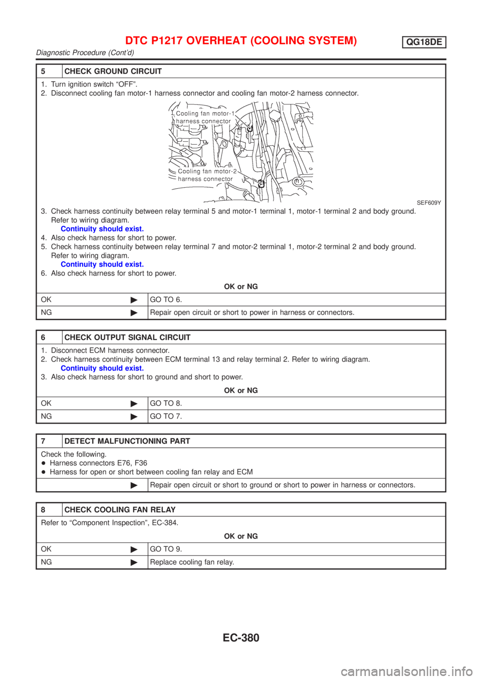
2. Disconnect cooling fan motor-1 harness connector and cooling fan motor-2 harness connector.
SEF609Y
3. Check harness continuity between relay terminal 5 and motor-1 terminal 1, motor-1 terminal 2 and body ground.
Refer to wiring diagram.
Continuity should exist.
4. Also check harness for short to power.
5. Check harness continuity between relay terminal 7 and motor-2 terminal 1, motor-2 terminal 2 and body ground.
Refer to wiring diagram.
Continuity should exist.
6. Also check harness for short to power.
OK or NG
OK©GO TO 6.
NG©Repair open circuit or short to power in harness or connectors.
6 CHECK OUTPUT SIGNAL CIRCUIT
1. Disconnect ECM harness connector.
2. Check harness continuity between ECM terminal 13 and relay terminal 2. Refer to wiring diagram.
Continuity should exist.
3. Also check harness for short to ground and short to power.
OK or NG
OK©GO TO 8.
NG©GO TO 7.
7 DETECT MALFUNCTIONING PART
Check the following.
+Harness connectors E76, F36
+Harness for open or short between cooling fan relay and ECM
©Repair open circuit or short to ground or short to power in harness or connectors.
8 CHECK COOLING FAN RELAY
Refer to ªComponent Inspectionº, EC-384.
OK or NG
OK©GO TO 9.
NG©Replace cooling fan relay.
DTC P1217 OVERHEAT (COOLING SYSTEM)QG18DE
Diagnostic Procedure (Cont'd)
EC-380
Page 814 of 3051
Wiring DiagramNLEC0346MODELS WITH ECM IN ENGINE COMPARTMENTNLEC0346S01
YEC670
DTC P1401 EGR TEMPERATURE SENSOR (WHERE FITTED)QG18DE
Wiring Diagram
EC-389
Page 815 of 3051
MODELS WITH ECM IN CABINNLEC0346S02
YEC891
DTC P1401 EGR TEMPERATURE SENSOR (WHERE FITTED)QG18DE
Wiring Diagram (Cont'd)
EC-390
Page 816 of 3051
Diagnostic ProcedureNLEC0347
1 CHECK POWER SUPPLY
1. Turn ignition switch ªOFFº.
2. Disconnect EGR temperature sensor harness connector.
SEF127X
3. Turn ignition switch ªONº.
4. Check voltage between terminal 1 and ground with CONSULT-II or tester.
SEF500Y
OK or NG
OK©GO TO 2.
NG©Repair harness or connectors.
2 CHECK GROUND CIRCUIT
1. Turn ignition switch ªOFFº.
2. Check harness continuity between EGR temperature sensor harness terminal 2 and engine ground.
Refer to wiring diagram.
Continuity should exist.
3. Also check harness for short to power.
OK or NG
OK©GO TO 4.
NG©GO TO 3.
3 DETECT MALFUNCTIONING PART
Check the following.
+Harness for open or short between EGR temperature sensor and ECM
+Joint connector-1 (where fitted)
+Joint connector F46 (where fitted)
©Repair open circuit or short to power in harness or connector.
DTC P1401 EGR TEMPERATURE SENSOR (WHERE FITTED)QG18DE
Diagnostic Procedure
EC-391
Page 822 of 3051
Wiring DiagramNLEC0352MODELS WITH ECM IN ENGINE COMPARTMENTNLEC0352S01
YEC664
DTC P1402 EGR FUNCTION (OPEN) (WHERE FITTED)QG18DE
Wiring Diagram
EC-397
Page 823 of 3051
MODELS WITH ECM IN CABINNLEC0352S02
YEC884
DTC P1402 EGR FUNCTION (OPEN) (WHERE FITTED)QG18DE
Wiring Diagram (Cont'd)
EC-398
Page 824 of 3051

Diagnostic ProcedureNLEC0353
1 CHECK POWER SUPPLY
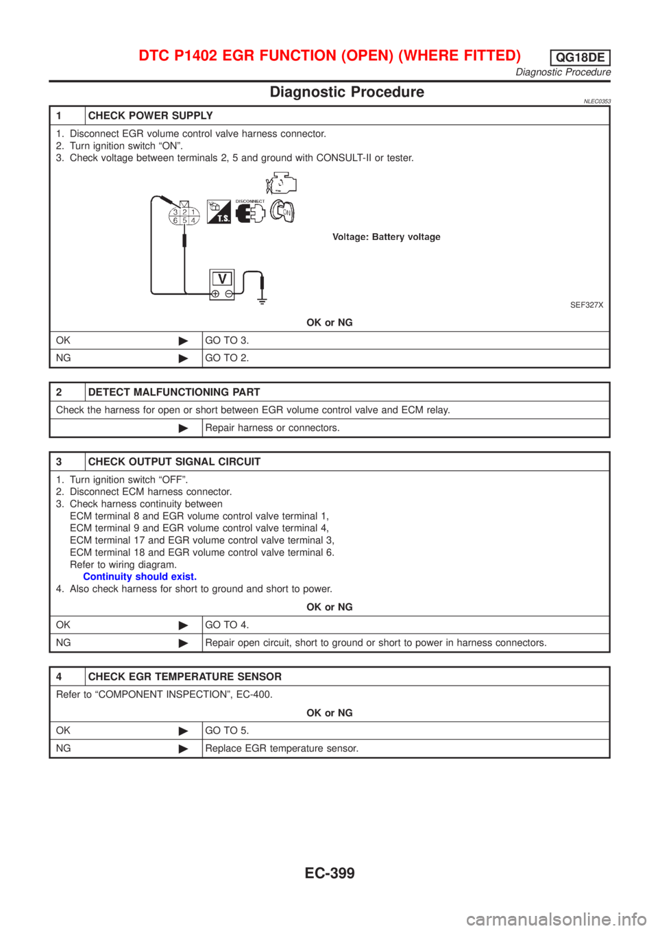
1. Disconnect EGR volume control valve harness connector.
2. Turn ignition switch ªONº.
3. Check voltage between terminals 2, 5 and ground with CONSULT-II or tester.
SEF327X
OK or NG
OK©GO TO 3.
NG©GO TO 2.
2 DETECT MALFUNCTIONING PART
Check the harness for open or short between EGR volume control valve and ECM relay.
©Repair harness or connectors.
3 CHECK OUTPUT SIGNAL CIRCUIT
1. Turn ignition switch ªOFFº.
2. Disconnect ECM harness connector.
3. Check harness continuity between
ECM terminal 8 and EGR volume control valve terminal 1,
ECM terminal 9 and EGR volume control valve terminal 4,
ECM terminal 17 and EGR volume control valve terminal 3,
ECM terminal 18 and EGR volume control valve terminal 6.
Refer to wiring diagram.
Continuity should exist.
4. Also check harness for short to ground and short to power.
OK or NG
OK©GO TO 4.
NG©Repair open circuit, short to ground or short to power in harness connectors.
4 CHECK EGR TEMPERATURE SENSOR
Refer to ªCOMPONENT INSPECTIONº, EC-400.
OK or NG
OK©GO TO 5.
NG©Replace EGR temperature sensor.
DTC P1402 EGR FUNCTION (OPEN) (WHERE FITTED)QG18DE
Diagnostic Procedure
EC-399