Page 718 of 3051
Diagnostic ProcedureNLEC0211
1 RETIGHTEN GROUND SCREWS
Loosen and retighten engine ground screws.
JEF104Y
©GO TO 2.
2 CHECK INPUT SIGNAL CIRCUIT-1
1. Turn ignition switch ªOFFº.
2. Disconnect ECM harness connector and knock sensor harness connector.
JEF110Y
3. Check harness continuity between knock sensor signal terminal 1 and ECM terminal 81.
Refer to wiring diagram.
Continuity should exist.
4. Also check harness for short to ground and short to power.
OK or NG
OK©GO TO 4.
NG©GO TO 3.
3 DETECT MALFUNCTIONING PART
Check the harness for open or short between knock sensor and ECM.
©Repair open circuit or short to ground or short to power in harness or connectors.
4 CHECK KNOCK SENSOR
Refer to ªComponent Inspectionº, EC-294.
OK or NG
OK©GO TO 5.
NG©Replace knock sensor.
DTC P0325 KNOCK SENSOR (KS)QG18DE
Diagnostic Procedure
EC-293
Page 722 of 3051
Wiring DiagramNLEC0555MODELS WITH ECM IN ENGINE COMPARTMENTNLEC0555S01
YEC662
DTC P0335 CRANKSHAFT POSITION SENSOR (POS)QG18DE
Wiring Diagram
EC-297
Page 723 of 3051
MODELS WITH ECM IN CABINNLEC0555S02
YEC882
DTC P0335 CRANKSHAFT POSITION SENSOR (POS)QG18DE
Wiring Diagram (Cont'd)
EC-298
Page 725 of 3051

3 DETECT MALFUNCTIONING PART
Check the following.
+Joint connector-3 (where fitted)
+Harness connectors M72, F44 (where fitted)
+Harness connectors M11, E106 (LHD models) (where fitted)
+Harness connectors M78, E120 (RHD models) (where fitted)
+Joint connector F46 (where fitted)
+Harness connectors E76, F36 (where fitted)
+Harness for open or short between joint connector and ECM relay
+Harness for open or short between crankshaft position sensor and joint connector
+Harness for open or short between joint connector and ECM
+ECM relay
©Repair open circuit or short to ground or short to power in harness or connectors.
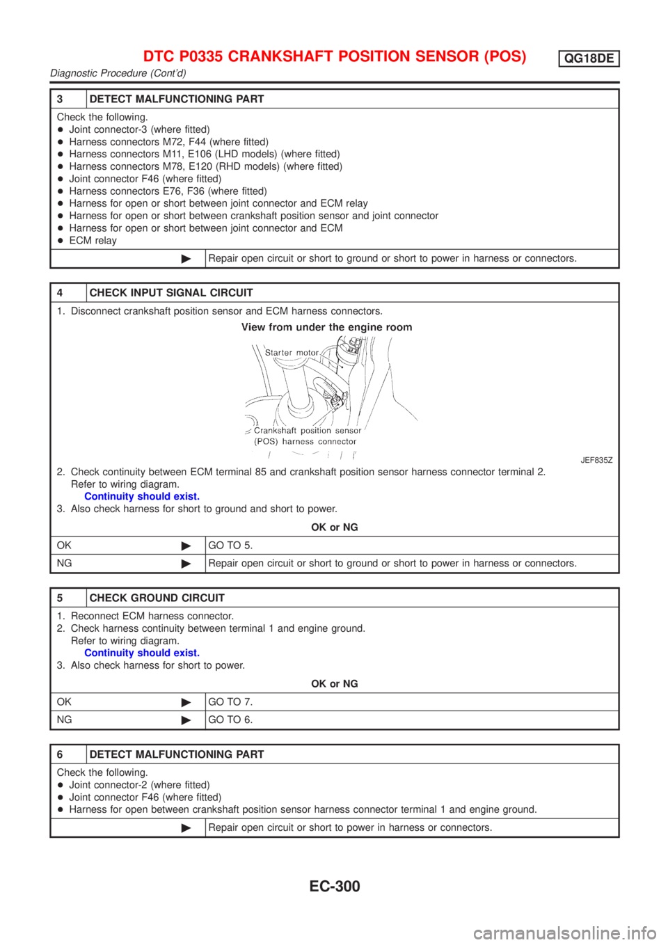
4 CHECK INPUT SIGNAL CIRCUIT
1. Disconnect crankshaft position sensor and ECM harness connectors.
JEF835Z
2. Check continuity between ECM terminal 85 and crankshaft position sensor harness connector terminal 2.
Refer to wiring diagram.
Continuity should exist.
3. Also check harness for short to ground and short to power.
OK or NG
OK©GO TO 5.
NG©Repair open circuit or short to ground or short to power in harness or connectors.
5 CHECK GROUND CIRCUIT
1. Reconnect ECM harness connector.
2. Check harness continuity between terminal 1 and engine ground.
Refer to wiring diagram.
Continuity should exist.
3. Also check harness for short to power.
OK or NG
OK©GO TO 7.
NG©GO TO 6.
6 DETECT MALFUNCTIONING PART
Check the following.
+Joint connector-2 (where fitted)
+Joint connector F46 (where fitted)
+Harness for open between crankshaft position sensor harness connector terminal 1 and engine ground.
©Repair open circuit or short to power in harness or connectors.
DTC P0335 CRANKSHAFT POSITION SENSOR (POS)QG18DE
Diagnostic Procedure (Cont'd)
EC-300
Page 729 of 3051
Wiring DiagramNLEC0224MODELS WITH ECM IN ENGINE COMPARTMENTNLEC0224S01
YEC663
DTC P0340 CAMSHAFT POSITION SENSOR (CMPS) (PHASE)QG18DE
Wiring Diagram
EC-304
Page 730 of 3051
MODELS WITH ECM IN CABINNLEC0224S02
YEC883
DTC P0340 CAMSHAFT POSITION SENSOR (CMPS) (PHASE)QG18DE
Wiring Diagram (Cont'd)
EC-305
Page 732 of 3051

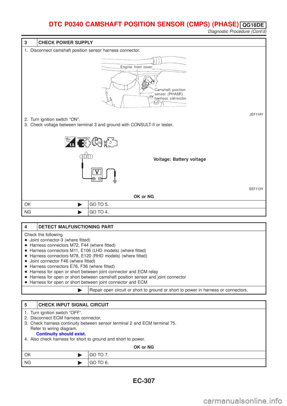
3 CHECK POWER SUPPLY
1. Disconnect camshaft position sensor harness connector.
JEF114Y
2. Turn ignition switch ªONº.
3. Check voltage between terminal 3 and ground with CONSULT-II or tester.
SEF113Y
OK or NG
OK©GO TO 5.
NG©GO TO 4.
4 DETECT MALFUNCTIONING PART
Check the following.
+Joint connector-3 (where fitted)
+Harness connectors M72, F44 (where fitted)
+Harness connectors M11, E106 (LHD models) (where fitted)
+Harness connectors M78, E120 (RHD models) (where fitted)
+Joint connector F46 (where fitted)
+Harness connectors E76, F36 (where fitted)
+Harness for open or short between joint connector and ECM relay
+Harness for open or short between camshaft position sensor and joint connector
+Harness for open or short between joint connector and ECM
©Repair open circuit or short to ground or short to power in harness or connectors.
5 CHECK INPUT SIGNAL CIRCUIT
1. Turn ignition switch ªOFFº.
2. Disconnect ECM harness connector.
3. Check harness continuity between sensor terminal 2 and ECM terminal 75.
Refer to wiring diagram.
Continuity should exist.
4. Also check harness for short to ground and short to power.
OK or NG
OK©GO TO 7.
NG©GO TO 6.
DTC P0340 CAMSHAFT POSITION SENSOR (CMPS) (PHASE)QG18DE
Diagnostic Procedure (Cont'd)
EC-307
Page 733 of 3051

6 DETECT MALFUNCTIONING PART
Check the harness for open or short between ECM and camshaft position sensor.
©Repair open circuit or short to ground or short to power in harness or connectors.
7 CHECK GROUND CIRCUIT
1. Turn ignition switch ªOFFº.
2. Check harness continuity between sensor terminal 3 and engine ground.
Refer to wiring diagram.
Continuity should exist.
3. Also check harness for short to power.
OK or NG
OK©GO TO 9.
NG©GO TO 8.
8 DETECT MALFUNCTIONING PART
Check the following.
+Joint connector-2 (where fitted)
+Joint connector F46 (where fitted)
+Harness for open between camshaft position sensor (PHASE) and ground.
©Repair open circuit or short to power in harness connectors.
9 CHECK CAMSHAFT POSITION SENSOR
Refer to ªComponent Inspectionº, EC-308.
OK or NG
OK©GO TO 10.
NG©Replace camshaft position sensor.
10 CHECK INTERMITTENT INCIDENT
Perform ªTROUBLE DIAGNOSIS FOR INTERMITTENT INCIDENTº, EC-145.
©INSPECTION END
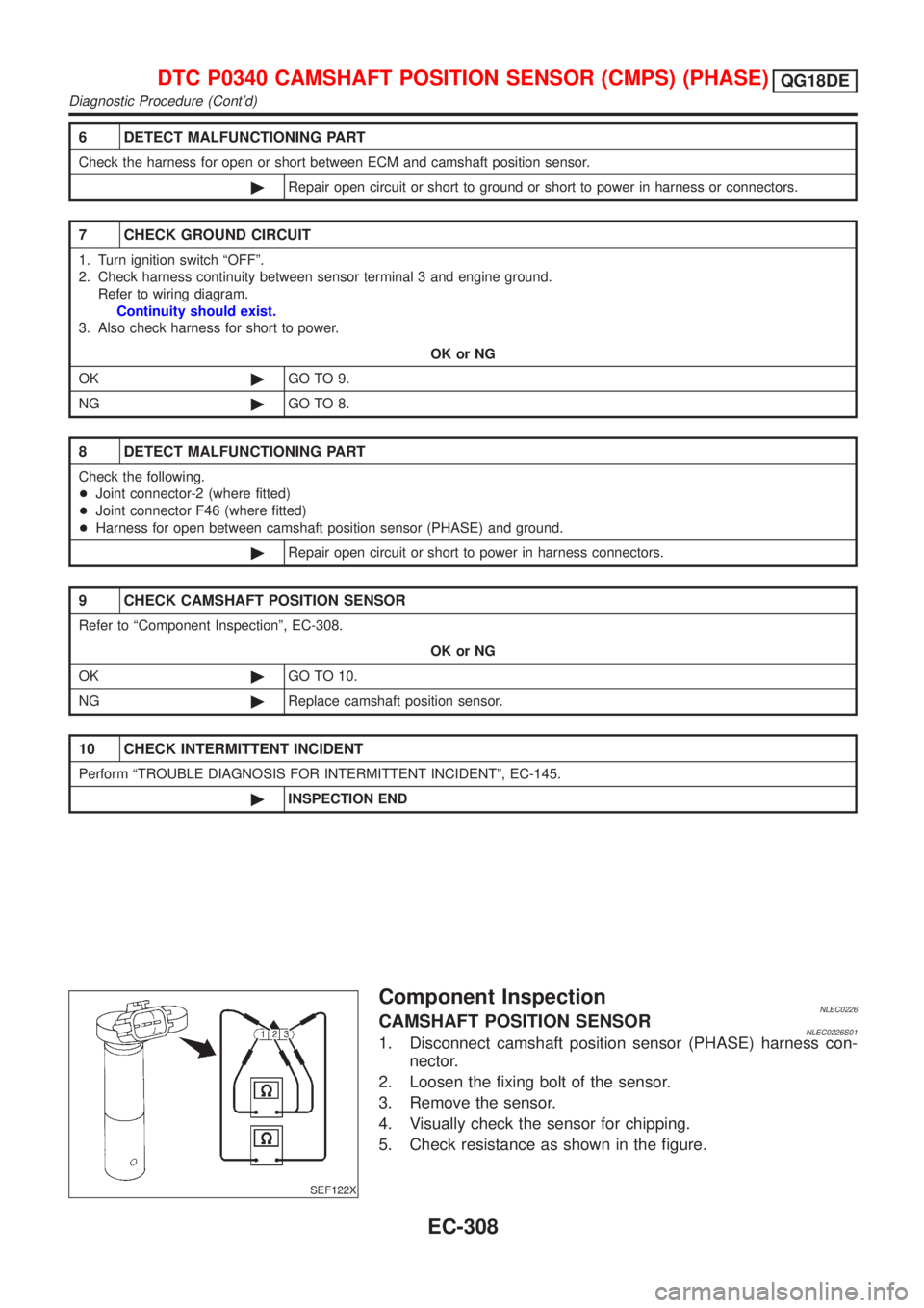
SEF122X
Component InspectionNLEC0226CAMSHAFT POSITION SENSORNLEC0226S011. Disconnect camshaft position sensor (PHASE) harness con-
nector.
2. Loosen the fixing bolt of the sensor.
3. Remove the sensor.
4. Visually check the sensor for chipping.
5. Check resistance as shown in the figure.
DTC P0340 CAMSHAFT POSITION SENSOR (CMPS) (PHASE)QG18DE
Diagnostic Procedure (Cont'd)
EC-308