Page 692 of 3051
Diagnostic ProcedureNLEC0186
1 CHECK POWER SUPPLY
1. Turn ignition switch ªOFFº.
2. Disconnect heated oxygen sensor 2 (rear) harness connector.
SEF639Z
3. Turn ignition switch ªONº.
4. Check voltage between terminal 2 and ground.
SEF218W
OK or NG
OK©GO TO 3.
NG©GO TO 2.
2 DETECT MALFUNCTIONING PART
Check the following.
+Harness connectors F38, M50 (where fitted)
+Harness connectors F44, M72 (where fitted)
+Harness for open or short between heated oxygen sensor 2 (rear) and fuse
+10A fuse
©Repair harness or connectors.
3 CHECK OUTPUT SIGNAL CIRCUIT
1. Turn ignition switch ªOFFº.
2. Disconnect ECM harness connector.
3. Check harness continuity between heated oxygen sensor 2 (rear) harness connector terminal 3 and ECM terminal 3.
Refer to wiring diagram.
Continuity should exist.
4. Also check harness for short to ground and short to power.
OK or NG
OK©GO TO 5.
NG©GO TO 4.
DTC P0141 HEATED OXYGEN SENSOR 2 HEATER (REAR)QG18DE
Diagnostic Procedure
EC-267
Page 696 of 3051
Wiring DiagramNLEC0190MODELS WITH ECM IN ENGINE COMPARTMENTNLEC0190S03
YEC659
DTC P0171 FUEL INJECTION SYSTEM FUNCTION
(LEAN SIDE)
QG18DE
Wiring Diagram
EC-271
Page 697 of 3051
MODELS WITH ECM IN CABINNLEC0190S04
YEC881
DTC P0171 FUEL INJECTION SYSTEM FUNCTION
(LEAN SIDE)
QG18DE
Wiring Diagram (Cont'd)
EC-272
Page 698 of 3051

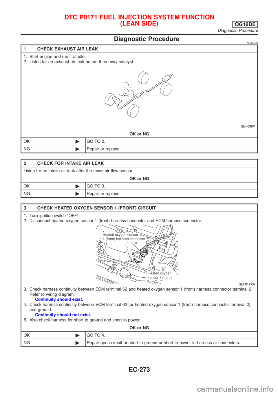
Diagnostic ProcedureNLEC0191
1 CHECK EXHAUST AIR LEAK
1. Start engine and run it at idle.
2. Listen for an exhaust air leak before three way catalyst.
SEF099P
OK or NG
OK©GO TO 2.
NG©Repair or replace.
2 CHECK FOR INTAKE AIR LEAK
Listen for an intake air leak after the mass air flow sensor.
OK or NG
OK©GO TO 3.
NG©Repair or replace.
3 CHECK HEATED OXYGEN SENSOR 1 (FRONT) CIRCUIT
1. Turn ignition switch ªOFFº.
2. Disconnect heated oxygen sensor 1 (front) harness connector and ECM harness connector.
SEF012XA
3. Check harness continuity between ECM terminal 62 and heated oxygen sensor 1 (front) harness connector terminal 2.
Refer to wiring diagram.
Continuity should exist.
4. Check harness continuity between ECM terminal 62 [or heated oxygen sensor 1 (front) harness connector terminal 2]
and ground.
Continuity should not exist.
5. Also check harness for short to ground and short to power.
OK or NG
OK©GO TO 4.
NG©Repair open circuit or short to ground or short to power in harness or connectors.
DTC P0171 FUEL INJECTION SYSTEM FUNCTION
(LEAN SIDE)
QG18DE
Diagnostic Procedure
EC-273
Page 704 of 3051
Wiring DiagramNLEC0194MODELS WITH ECM IN ENGINE COMPARTMENTNLEC0194S03
YEC659
DTC P0172 FUEL INJECTION SYSTEM FUNCTION
(RICH SIDE)
QG18DE
Wiring Diagram
EC-279
Page 705 of 3051
MODELS WITH ECM IN CABINNLEC0194S04
YEC881
DTC P0172 FUEL INJECTION SYSTEM FUNCTION
(RICH SIDE)
QG18DE
Wiring Diagram (Cont'd)
EC-280
Page 706 of 3051
Diagnostic ProcedureNLEC0195
1 CHECK FOR EXHAUST AIR LEAK
1. Start engine and run it at idle.
2. Listen for an exhaust air leak before the three way catalyst.
SEF099P
OK or NG
OK©GO TO 2.
NG©Repair or replace.
2 CHECK HEATED OXYGEN SENSOR 1 (FRONT) CIRCUIT
1. Turn ignition switch ªOFFº.
2. Disconnect heated oxygen sensor 1 (front) harness connector and ECM harness connector.
SEF012XA
3. Check harness continuity between ECM terminal 62 and heated oxygen sensor 1 (front) harness connector terminal 2.
Refer to wiring diagram.
Continuity should exist.
4. Check harness continuity between ECM terminal 62 [or heated oxygen sensor 1 (front) harness connector terminal 2]
and ground.
Continuity should not exist.
5. Also check harness for short to ground and short to power.
OK or NG
OK©GO TO 3.
NG©Repair open circuit or short to ground or short to power in harness or connectors.
DTC P0172 FUEL INJECTION SYSTEM FUNCTION
(RICH SIDE)
QG18DE
Diagnostic Procedure
EC-281
Page 717 of 3051
Wiring DiagramNLEC0210
YEC657
DTC P0325 KNOCK SENSOR (KS)QG18DE
Wiring Diagram
EC-292