Page 780 of 3051
Diagnostic ProcedureNLEC0293
1 CHECK POWER SUPPLY
1. Turn ignition switch ªOFFº.
2. Disconnect throttle position switch harness connector.
JEF091Y
3. Turn ignition switch ªONº.
4. Check voltage between terminal 5 and engine ground with CONSULT-II or tester.
SEF837X
Voltage: Battery voltage
OK or NG
OK©GO TO 3.
NG©GO TO 2.
2 DETECT MALFUNCTIONING PART
Check the following.
+Harness connectors E75, F35
+10A fuse
+Harness for open or short between throttle position switch and fuse
©Repair harness or connectors.
3 CHECK INPUT SIGNAL CIRCUIT
1. Turn ignition switch ªOFFº.
2. Disconnect ECM harness connector.
3. Check harness continuity between ECM terminal 40 and terminal 4.
Refer to wiring diagram.
Continuity should exist.
4. Also check harness for short to ground and short to power.
OK or NG
OK©GO TO 5.
NG©GO TO 4.
DTC P0510 CLOSED THROTTLE POSITION SWITCH
(WHERE FITTED)
QG18DE
Diagnostic Procedure
EC-355
Page 782 of 3051
1) Start engine and warm it up to normal operating temperature.
2) Turn ignition switch ªOFFº.
3) Disconnect throttle position switch harness connector.
4) Check continuity between terminals 4 and 5 under the follow-
ing conditions. Refer to wiring diagram.
NOTE:
Continuity measurement must be made with closed throttle
position switch installed in vehicle.
Throttle valve conditions Continuity
Completely closed Yes
Partially open or completely open No
If NG, adjust closed throttle position switch. Refer to ªBasic
Inspectionº, EC-99.
5) If it is impossible to adjust closed throttle position switch in
ªBasic Inspectionº, replace closed throttle position switch.
DTC P0510 CLOSED THROTTLE POSITION SWITCH
(WHERE FITTED)
QG18DE
Component Inspection (Cont'd)
EC-357
Page 787 of 3051
Wiring DiagramNLEC0519MODELS WITH ECM IN ENGINE COMPARTMENTNLEC0519S01
YEC680
D T C P 1111INTAKE VALVE TIMING CONTROL
SOLENOID VALVE
QG18DE
Wiring Diagram
EC-362
Page 788 of 3051
MODELS WITH ECM IN CABINNLEC0519S02
YEC889
D T C P 1111INTAKE VALVE TIMING CONTROL
SOLENOID VALVE
QG18DE
Wiring Diagram (Cont'd)
EC-363
Page 789 of 3051

Diagnostic ProcedureNLEC0520
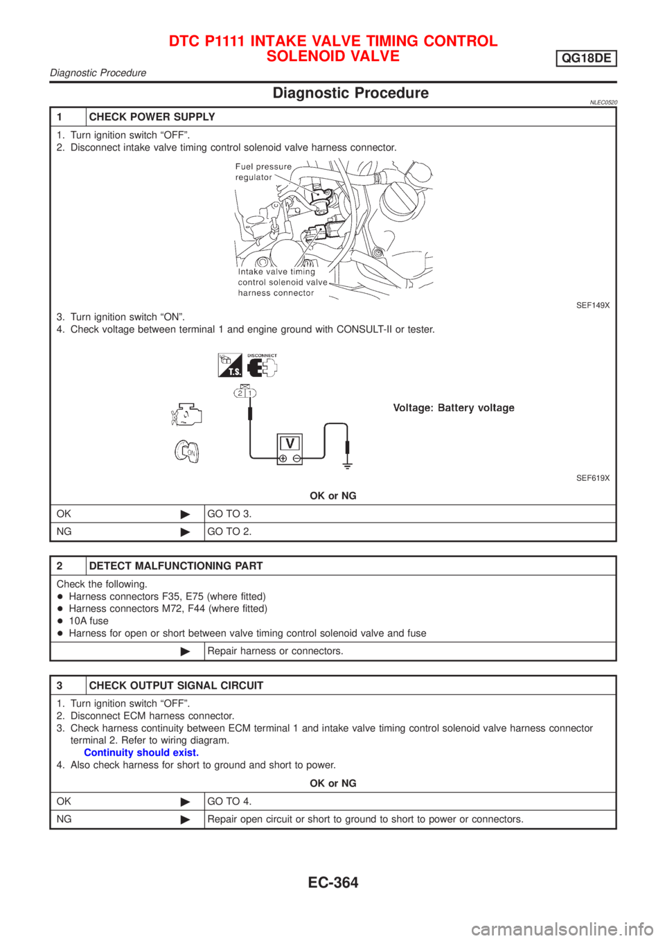
1 CHECK POWER SUPPLY
1. Turn ignition switch ªOFFº.
2. Disconnect intake valve timing control solenoid valve harness connector.
SEF149X
3. Turn ignition switch ªONº.
4. Check voltage between terminal 1 and engine ground with CONSULT-II or tester.
SEF619X
OK or NG
OK©GO TO 3.
NG©GO TO 2.
2 DETECT MALFUNCTIONING PART
Check the following.
+Harness connectors F35, E75 (where fitted)
+Harness connectors M72, F44 (where fitted)
+10A fuse
+Harness for open or short between valve timing control solenoid valve and fuse
©Repair harness or connectors.
3 CHECK OUTPUT SIGNAL CIRCUIT
1. Turn ignition switch ªOFFº.
2. Disconnect ECM harness connector.
3. Check harness continuity between ECM terminal 1 and intake valve timing control solenoid valve harness connector
terminal 2. Refer to wiring diagram.
Continuity should exist.
4. Also check harness for short to ground and short to power.
OK or NG
OK©GO TO 4.
NG©Repair open circuit or short to ground to short to power or connectors.
D T C P 1111INTAKE VALVE TIMING CONTROL
SOLENOID VALVE
QG18DE
Diagnostic Procedure
EC-364
Page 794 of 3051
Wiring DiagramNLEC0528
YEC681
DTC P1131 SWIRL CONTROL VALVE SOLENOID VALVE (CIRCUIT)
(WHERE FITTED)
QG18DE
Wiring Diagram
EC-369
Page 796 of 3051

5 CHECK OUTPUT SIGNAL CIRCUIT
1. Turn ignition switch ªOFFº.
2. Disconnect ECM harness connector.
3. Check harness continuity between ECM terminal 104 and swirl control valve control solenoid valve harness connector
terminal 2 with CONSULT-II or tester.
Refer to wiring diagram.
Continuity should exist.
If OK, check harness for short to ground and short to power.
OK or NG
OK©GO TO 6.
NG©Repair open circuit, short to ground or short to power in harness connectors.
6 CHECK SWIRL CONTROL VALVE CONTROL SOLENOID VALVE
Refer to ªCOMPONENT INSPECTIONº, EC-371.
OK or NG
OK©GO TO 7.
NG©Replace swirl control valve control solenoid valve.
7 CHECK INTERMITTENT INCIDENT
Perform ªTROUBLE DIAGNOSIS FOR INTERMITTENT INCIDENTº, EC-145.
©INSPECTION END
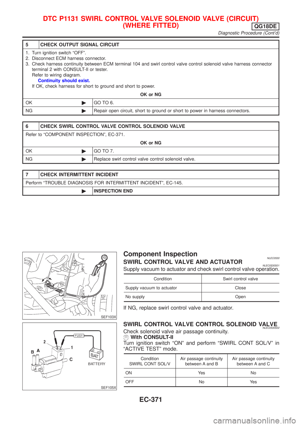
SEF103X
Component InspectionNLEC0530SWIRL CONTROL VALVE AND ACTUATORNLEC0530S01Supply vacuum to actuator and check swirl control valve operation.
Condition Swirl control valve
Supply vacuum to actuator Close
No supply Open
If NG, replace swirl control valve and actuator.
SEF105X
SWIRL CONTROL VALVE CONTROL SOLENOID VALVENLEC0530S02Check solenoid valve air passage continuity.
With CONSULT-II
Turn ignition switch ªONº and perform ªSWIRL CONT SOL/Vº in
ªACTIVE TESTº mode.
Condition
SWIRL CONT SOL/VAir passage continuity
between A and BAir passage continuity
between A and C
ON Yes No
OFF No Yes
DTC P1131 SWIRL CONTROL VALVE SOLENOID VALVE (CIRCUIT)
(WHERE FITTED)
QG18DE
Diagnostic Procedure (Cont'd)
EC-371
Page 801 of 3051
Wiring DiagramNLEC0490MODELS WITH FUSE AND FUSIBLE LINK BOX E43NLEC0490S03
YEC682
DTC P1217 OVERHEAT (COOLING SYSTEM)QG18DE
Wiring Diagram
EC-376