Page 2310 of 3051

Removal and InstallationNLEM0024CAUTION:
+When installing sliding parts such as bearings and
pistons, apply engine oil on the sliding surfaces.
+Place removed parts, such as bearings and bearing caps,
in their proper order and direction.
+When installing connecting rod nuts and main bearing cap
bolts, apply new engine oil to threads and seating sur-
faces.
+Do not allow any magnetic materials to contact the signal
plate teeth of flywheel or drive plate, and rear plate.
+Remove the crankshaft position sensor (POS).
+Be careful not to damage sensor edges and single plate
teeth.
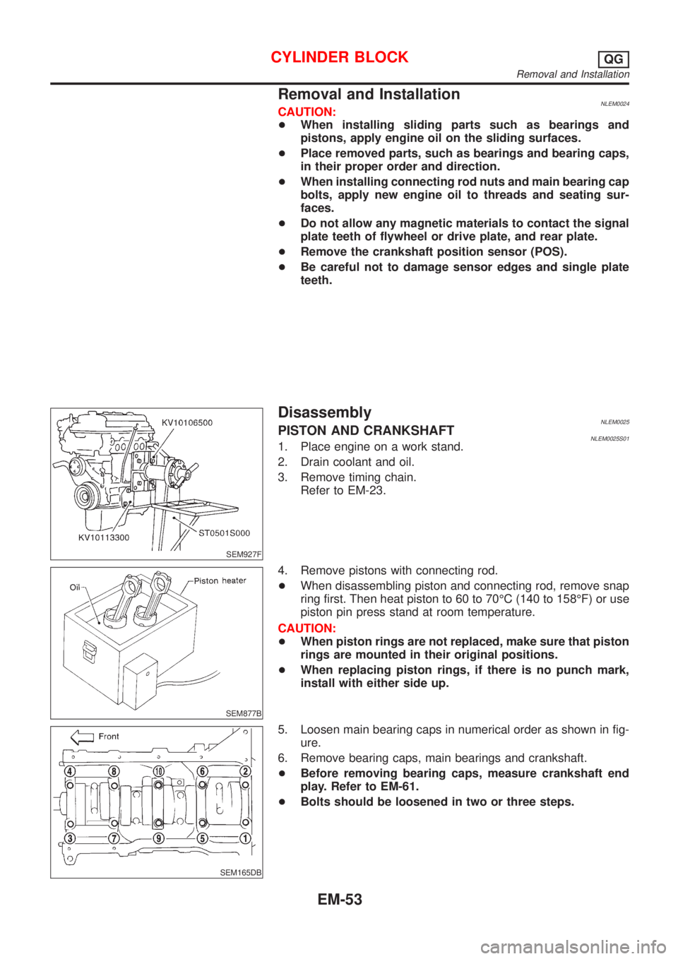
SEM927F
DisassemblyNLEM0025PISTON AND CRANKSHAFTNLEM0025S011. Place engine on a work stand.
2. Drain coolant and oil.
3. Remove timing chain.
Refer to EM-23.
SEM877B
4. Remove pistons with connecting rod.
+When disassembling piston and connecting rod, remove snap
ring first. Then heat piston to 60 to 70ÉC (140 to 158ÉF) or use
piston pin press stand at room temperature.
CAUTION:
+When piston rings are not replaced, make sure that piston
rings are mounted in their original positions.
+When replacing piston rings, if there is no punch mark,
install with either side up.
SEM165DB
5. Loosen main bearing caps in numerical order as shown in fig-
ure.
6. Remove bearing caps, main bearings and crankshaft.
+Before removing bearing caps, measure crankshaft end
play. Refer to EM-61.
+Bolts should be loosened in two or three steps.
CYLINDER BLOCKQG
Removal and Installation
EM-53
Page 2317 of 3051

SEM062A
REPLACEMENT OF CONNECTING ROD BUSHING
(SMALL END)
NLEM0026S101. Drive in small end bushing until it is flush with end surface of
rod.
Be sure to align the oil holes.
2. Ream the bushing so that clearance with piston pin is within
specification.
Clearance between connecting rod bushing and piston
pin:
0.005 - 0.017 mm (0.0002 - 0.0007 in)
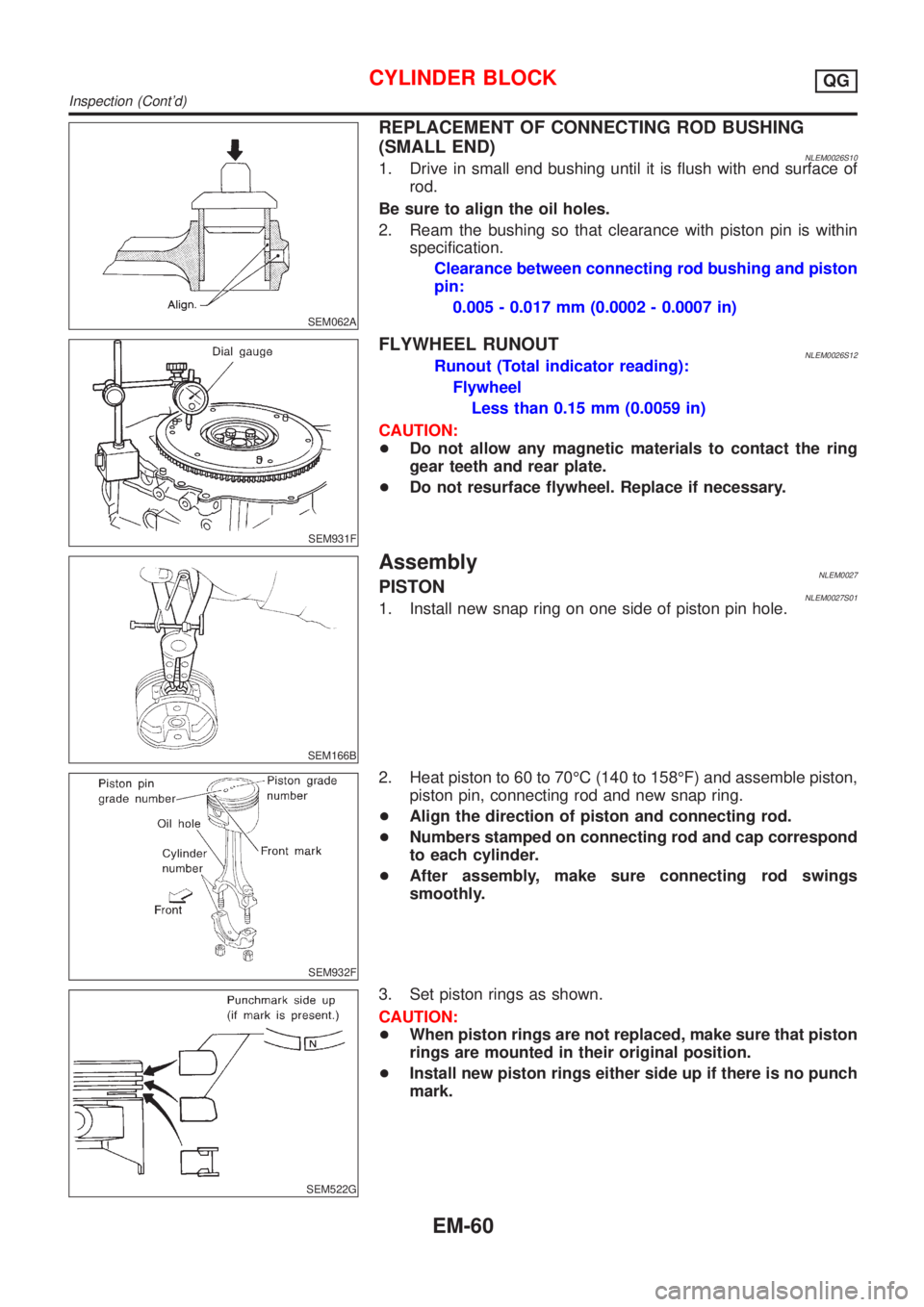
SEM931F
FLYWHEEL RUNOUTNLEM0026S12Runout (Total indicator reading):
Flywheel
Less than 0.15 mm (0.0059 in)
CAUTION:
+Do not allow any magnetic materials to contact the ring
gear teeth and rear plate.
+Do not resurface flywheel. Replace if necessary.
SEM166B
AssemblyNLEM0027PISTONNLEM0027S011. Install new snap ring on one side of piston pin hole.
SEM932F
2. Heat piston to 60 to 70ÉC (140 to 158ÉF) and assemble piston,
piston pin, connecting rod and new snap ring.
+Align the direction of piston and connecting rod.
+Numbers stamped on connecting rod and cap correspond
to each cylinder.
+After assembly, make sure connecting rod swings
smoothly.
SEM522G
3. Set piston rings as shown.
CAUTION:
+When piston rings are not replaced, make sure that piston
rings are mounted in their original position.
+Install new piston rings either side up if there is no punch
mark.
CYLINDER BLOCKQG
Inspection (Cont'd)
EM-60
Page 2332 of 3051
Connecting Rod BearingNLEM0038STANDARD SIZENLEM0038S01Unit: mm (in)
Grade No. Thickness Identification color or number
0 1.503 - 1.506 (0.0592 - 0.0593) Ð
1 1.506 - 1.509 (0.0593 - 0.0594) Brown
2 1.509 - 1.512 (0.0594 - 0.0595) Green
UNDERSIZENLEM0038S02Unit: mm (in)
Grade No. Thickness Identification color or number
0.08 (0.0031) 1.542 - 1.546 (0.0607 - 0.0609) Ð
0.12 (0.0047) 1.562 - 1.566 (0.0615 - 0.0617) Ð
0.25 (0.0098) 1.627 - 1.631 (0.0641 - 0.0642) Ð
Bearing ClearanceNLEM0039Unit: mm (in)
Main bearing clearanceStandard 0.020 - 0.044 (0.0008 - 0.0017)
Limit 0.1 (0.004)
Connecting rod bearing clearanceStandard 0.014 - 0.039 (0.0006 - 0.0015)
Limit 0.1 (0.004)
Miscellaneous ComponentsNLEM0040Unit: mm (in)
Flywheel runout [TIR*]Less than 0.15 (0.0059)
Camshaft sprocket runout [TIR*] Less than 0.15 (0.0059)
*: Total indicator reading
SERVICE DATA AND SPECIFICATIONS (SDS)QG
Connecting Rod Bearing
EM-75
Page 2354 of 3051
CAUTION:
+After removing timing chain, do not turn crankshaft and
camshaft separately, or valves will strike piston heads.
+When installing chain tensioner, oil seals, or other sliding
parts, lubricate contacting surfaces with new engine oil.
+Apply new engine oil to bolt threads and seat surfaces
when installing camshaft sprocket and crankshaft pulley.
RemovalNLEM01261. Remove engine under cover.
2. Remove front RH wheel and engine side cover.
3. Drain coolant by removing cylinder block drain plug and lower
radiator hose. Refer to LC-38, ªChanging Engine Coolantº.
4. Remove drive belts and water pump pulley.
5. Disconnect the following parts:
+Vacuum hoses
+Wires
+Harness
+Connectors
SEM029G
6. Remove rocker cover bolts in numerical order.
7. Remove rocker cover.
SEM287G
8. Remove cylinder head outside bolts.
TIMING CHAINSR
Components (Cont'd)
EM-97
Page 2361 of 3051

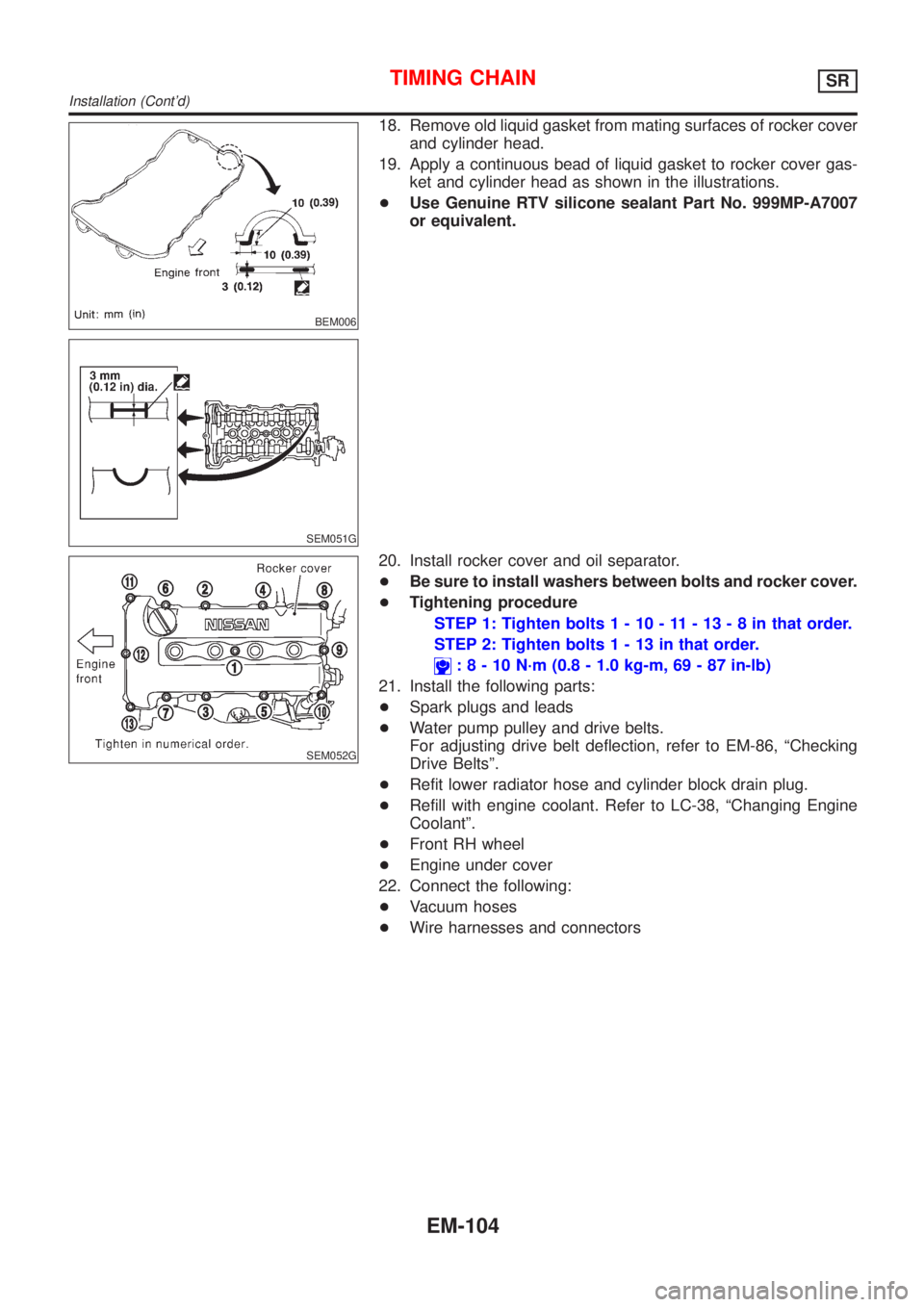
BEM006
SEM051G
18. Remove old liquid gasket from mating surfaces of rocker cover
and cylinder head.
19. Apply a continuous bead of liquid gasket to rocker cover gas-
ket and cylinder head as shown in the illustrations.
+Use Genuine RTV silicone sealant Part No. 999MP-A7007
or equivalent.
SEM052G
20. Install rocker cover and oil separator.
+Be sure to install washers between bolts and rocker cover.
+Tightening procedure
STEP 1: Tighten bolts1-10-11-13-8inthat order.
STEP 2: Tighten bolts1-13inthat order.
:8-10N´m(0.8 - 1.0 kg-m, 69 - 87 in-lb)
21. Install the following parts:
+Spark plugs and leads
+Water pump pulley and drive belts.
For adjusting drive belt deflection, refer to EM-86, ªChecking
Drive Beltsº.
+Refit lower radiator hose and cylinder block drain plug.
+Refill with engine coolant. Refer to LC-38, ªChanging Engine
Coolantº.
+Front RH wheel
+Engine under cover
22. Connect the following:
+Vacuum hoses
+Wire harnesses and connectors
TIMING CHAINSR
Installation (Cont'd)
EM-104
Page 2362 of 3051
SEM077D
ReplacementNLEM0129VALVE OIL SEALNLEM0129S011. Remove accelerator wire.
2. Remove rocker cover.
3. Remove camshafts and sprockets. Refer to EM-109.
4. Remove spark plugs.
5. Install air hose adapter into spark plug hole and apply air
pressure to hold valves in place. Apply a pressure of 490 kPa
(5 kg/cm
2, 71 psi).
6. Remove rocker arm, rocker arm guide and shim.
SEM604E
7. Remove valve spring with Tool. Temporarily install camshaft as
shown.
Piston concerned should be set at TDC to prevent valve from
falling.
SEM054G
8. Remove valve oil seal with a suitable tool.
SEM358E
9. Apply new engine oil to new valve oil seal and install it with
Tool.
SEM997C
FRONT OIL SEALNLEM0129S021. Remove the following parts:
+Engine under cover
+Front RH wheel and engine side cover
+Drive belts
+Crankshaft pulley
2. Remove front oil seal.
+Be careful not to scratch front cover.
OIL SEALSR
Replacement
EM-105
Page 2366 of 3051
RemovalNLEM01311. Release fuel pressure.
Refer to EC-578, ªFuel Pressure Releaseº.
2. Remove engine under covers.
3. Remove front RH wheel and engine side cover.
4. Drain coolant by removing cylinder block drain plug and radia-
tor drain cock. Refer to LC-38, ªChanging Engine Coolantº.
5. Remove radiator.
6. Remove air duct to intake manifold.
7. Disconnect the following parts:
+Vacuum hoses
+Fuel hoses
+Wires
+Harness
+Connectors
+Front exhaust tube
8. Remove all spark plugs.
SEM029G
9. Remove rocker cover bolts in numerical order.
10. Remove rocker cover.
SEM030G
11. Remove intake manifold supports.
SEM065G
12. Remove water pipe assembly.
CYLINDER HEADSR
Removal
EM-109
Page 2386 of 3051
SEM052G
17. Install rocker cover and oil separator.
+Be sure to install washers between bolts and rocker cover.
+Tightening procedure
STEP 1: Tighten bolts1-10-11-13-8inthat order.
STEP 2: Tighten bolts1-13inthat order.
:8-10N´m(0.8 - 1.0 kg-m, 69 - 87 in-lb)
18. Install the following parts:
+Spark plugs and leads
+Radiator
Refit hoses and refill with coolant.
Refer to LC-38, ªChanging Engine Coolantº.
+Front RH wheel
+Engine under covers
19. Connect the following:
+Vacuum hoses
+Fuel hoses
+Wire harnesses and connectors
+Air duct to intake manifold
+Front exhaust tube
CYLINDER HEADSR
Installation (Cont'd)
EM-129