Page 2387 of 3051
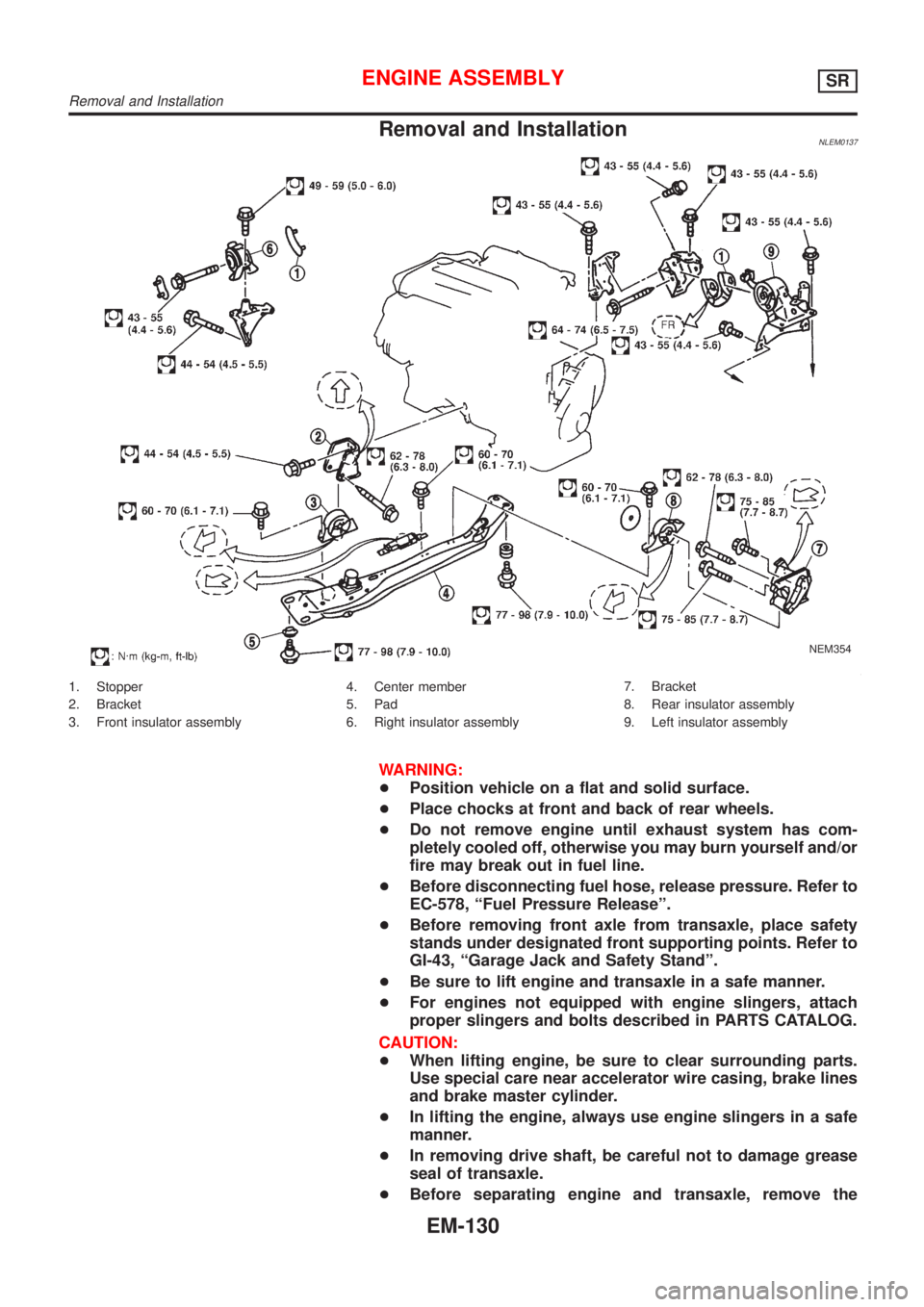
Removal and InstallationNLEM0137
NEM354
1. Stopper
2. Bracket
3. Front insulator assembly4. Center member
5. Pad
6. Right insulator assembly7. Bracket
8. Rear insulator assembly
9. Left insulator assembly
WARNING:
+Position vehicle on a flat and solid surface.
+Place chocks at front and back of rear wheels.
+Do not remove engine until exhaust system has com-
pletely cooled off, otherwise you may burn yourself and/or
fire may break out in fuel line.
+Before disconnecting fuel hose, release pressure. Refer to
EC-578, ªFuel Pressure Releaseº.
+Before removing front axle from transaxle, place safety
stands under designated front supporting points. Refer to
GI-43, ªGarage Jack and Safety Standº.
+Be sure to lift engine and transaxle in a safe manner.
+For engines not equipped with engine slingers, attach
proper slingers and bolts described in PARTS CATALOG.
CAUTION:
+When lifting engine, be sure to clear surrounding parts.
Use special care near accelerator wire casing, brake lines
and brake master cylinder.
+In lifting the engine, always use engine slingers in a safe
manner.
+In removing drive shaft, be careful not to damage grease
seal of transaxle.
+Before separating engine and transaxle, remove the
ENGINE ASSEMBLYSR
Removal and Installation
EM-130
Page 2388 of 3051
crankshaft position sensor (OBD) from the assembly.
+Always be extra careful not to damage edge of crankshaft
position sensor (OBD) or ring gear teeth.
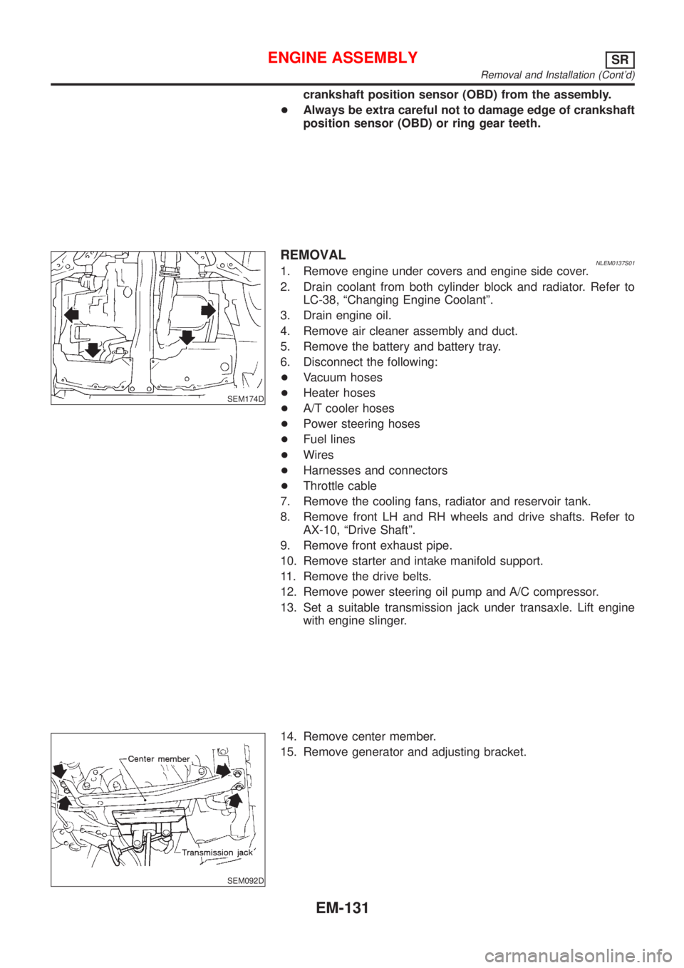
SEM174D
REMOVALNLEM0137S011. Remove engine under covers and engine side cover.
2. Drain coolant from both cylinder block and radiator. Refer to
LC-38, ªChanging Engine Coolantº.
3. Drain engine oil.
4. Remove air cleaner assembly and duct.
5. Remove the battery and battery tray.
6. Disconnect the following:
+Vacuum hoses
+Heater hoses
+A/T cooler hoses
+Power steering hoses
+Fuel lines
+Wires
+Harnesses and connectors
+Throttle cable
7. Remove the cooling fans, radiator and reservoir tank.
8. Remove front LH and RH wheels and drive shafts. Refer to
AX-10, ªDrive Shaftº.
9. Remove front exhaust pipe.
10. Remove starter and intake manifold support.
11. Remove the drive belts.
12. Remove power steering oil pump and A/C compressor.
13. Set a suitable transmission jack under transaxle. Lift engine
with engine slinger.
SEM092D
14. Remove center member.
15. Remove generator and adjusting bracket.
ENGINE ASSEMBLYSR
Removal and Installation (Cont'd)
EM-131
Page 2452 of 3051
CAUTION:
Do not disassemble or adjust the turbocharger body.
AssemblyNLEM0103S0102When a stud bolt is pulled out, tighten it to the following torque:
: 24 - 27 N´m (2.4 - 2.8 kg-m, 18 - 20 ft-lb)
JEM267G
InspectionNLEM0104EXHAUST MANIFOLDNLEM0104S01Check the distortion on the mounting surface in the six directions
using a straightedge and a feeler gauge.
Limit: 0.3 mm (0.012 in)
TURBOCHARGERNLEM0104S02
SEM269G
CAUTION:
When the compressor wheel, turbine wheel, or rotor shaft is
damaged, remove all the fragments and foreign matter left in
the following passages in order to prevent a secondary failure:
Suction side: Between turbocharger and air cleaner
Exhaust side: Between turbocharger and catalytic con-
verter
EXHAUST MANIFOLD, TURBOCHARGERYD
Disassembly and Assembly (Cont'd)
EM-195
Page 2453 of 3051
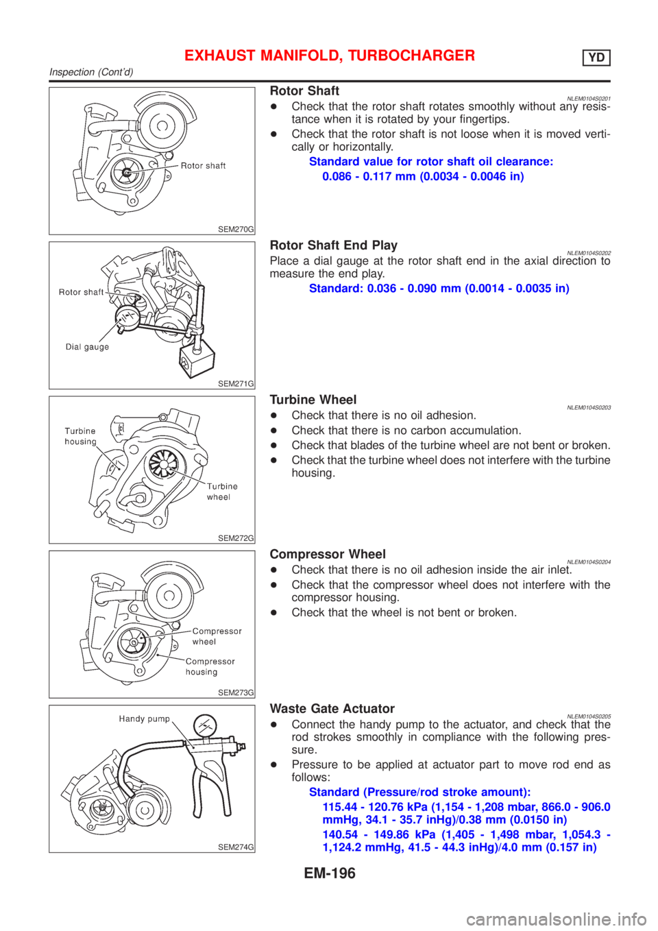
SEM270G
Rotor ShaftNLEM0104S0201+Check that the rotor shaft rotates smoothly without any resis-
tance when it is rotated by your fingertips.
+Check that the rotor shaft is not loose when it is moved verti-
cally or horizontally.
Standard value for rotor shaft oil clearance:
0.086 - 0.117 mm (0.0034 - 0.0046 in)
SEM271G
Rotor Shaft End PlayNLEM0104S0202Place a dial gauge at the rotor shaft end in the axial direction to
measure the end play.
Standard: 0.036 - 0.090 mm (0.0014 - 0.0035 in)
SEM272G
Turbine WheelNLEM0104S0203+Check that there is no oil adhesion.
+Check that there is no carbon accumulation.
+Check that blades of the turbine wheel are not bent or broken.
+Check that the turbine wheel does not interfere with the turbine
housing.
SEM273G
Compressor WheelNLEM0104S0204+Check that there is no oil adhesion inside the air inlet.
+Check that the compressor wheel does not interfere with the
compressor housing.
+Check that the wheel is not bent or broken.
SEM274G
Waste Gate ActuatorNLEM0104S0205+Connect the handy pump to the actuator, and check that the
rod strokes smoothly in compliance with the following pres-
sure.
+Pressure to be applied at actuator part to move rod end as
follows:
Standard (Pressure/rod stroke amount):
115.44 - 120.76 kPa (1,154 - 1,208 mbar, 866.0 - 906.0
mmHg, 34.1 - 35.7 inHg)/0.38 mm (0.0150 in)
140.54 - 149.86 kPa (1,405 - 1,498 mbar, 1,054.3 -
1,124.2 mmHg, 41.5 - 44.3 inHg)/4.0 mm (0.157 in)
EXHAUST MANIFOLD, TURBOCHARGERYD
Inspection (Cont'd)
EM-196
Page 2454 of 3051
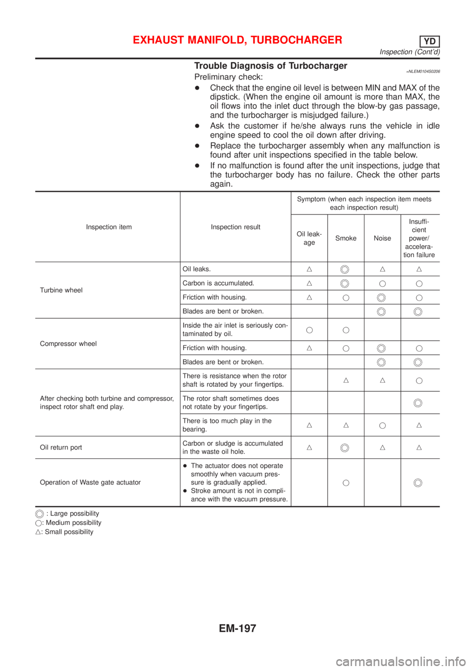
Trouble Diagnosis of Turbocharger=NLEM0104S0206Preliminary check:
+Check that the engine oil level is between MIN and MAX of the
dipstick. (When the engine oil amount is more than MAX, the
oil flows into the inlet duct through the blow-by gas passage,
and the turbocharger is misjudged failure.)
+Ask the customer if he/she always runs the vehicle in idle
engine speed to cool the oil down after driving.
+Replace the turbocharger assembly when any malfunction is
found after unit inspections specified in the table below.
+If no malfunction is found after the unit inspections, judge that
the turbocharger body has no failure. Check the other parts
again.
Inspection item Inspection resultSymptom (when each inspection item meets
each inspection result)
Oil leak-
ageSmoke NoiseInsuffi-
cient
power/
accelera-
tion failure
Turbine wheelOil leaks.n
nn
Carbon is accumulated.n
jj
Friction with housing.nj
j
Blades are bent or broken.
Compressor wheelInside the air inlet is seriously con-
taminated by oil.jj
Friction with housing.njj
Blades are bent or broken.
After checking both turbine and compressor,
inspect rotor shaft end play.There is resistance when the rotor
shaft is rotated by your fingertips.nnj
The rotor shaft sometimes does
not rotate by your fingertips.
There is too much play in the
bearing.nnjn
Oil return portCarbon or sludge is accumulated
in the waste oil hole.n
nn
Operation of Waste gate actuator+The actuator does not operate
smoothly when vacuum pres-
sure is gradually applied.
+Stroke amount is not in compli-
ance with the vacuum pressure.j
: Large possibility
j: Medium possibility
n: Small possibility
EXHAUST MANIFOLD, TURBOCHARGERYD
Inspection (Cont'd)
EM-197
Page 2475 of 3051
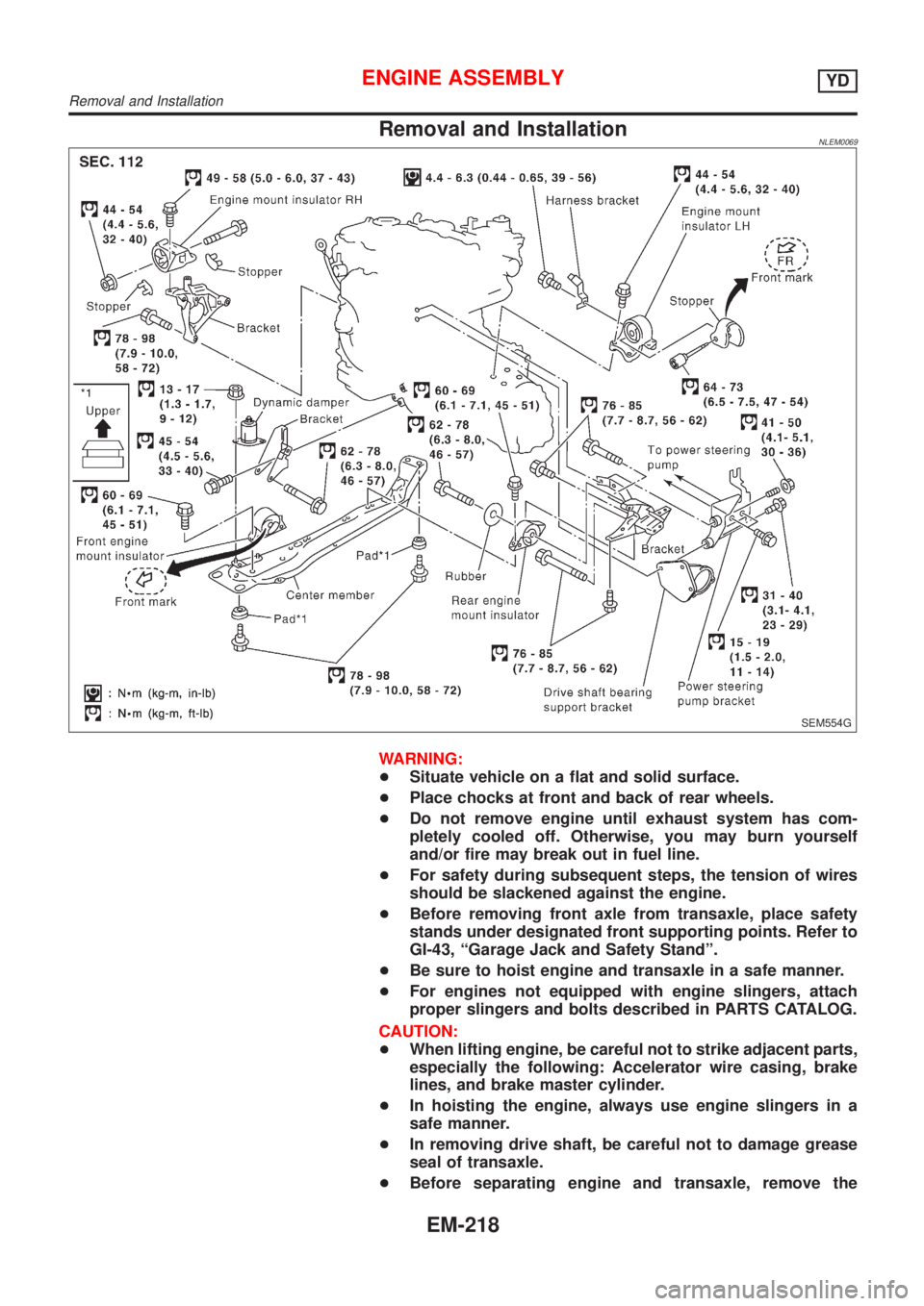
Removal and InstallationNLEM0069
SEM554G
WARNING:
+Situate vehicle on a flat and solid surface.
+Place chocks at front and back of rear wheels.
+Do not remove engine until exhaust system has com-
pletely cooled off. Otherwise, you may burn yourself
and/or fire may break out in fuel line.
+For safety during subsequent steps, the tension of wires
should be slackened against the engine.
+Before removing front axle from transaxle, place safety
stands under designated front supporting points. Refer to
GI-43, ªGarage Jack and Safety Standº.
+Be sure to hoist engine and transaxle in a safe manner.
+For engines not equipped with engine slingers, attach
proper slingers and bolts described in PARTS CATALOG.
CAUTION:
+When lifting engine, be careful not to strike adjacent parts,
especially the following: Accelerator wire casing, brake
lines, and brake master cylinder.
+In hoisting the engine, always use engine slingers in a
safe manner.
+In removing drive shaft, be careful not to damage grease
seal of transaxle.
+Before separating engine and transaxle, remove the
ENGINE ASSEMBLYYD
Removal and Installation
EM-218
Page 2476 of 3051
crankshaft position sensor (TDC sensor) from the assem-
bly.
+Always pay extra attention not to damage edge of crank-
shaft position sensor (TDC sensor) or ring gear teeth.
REMOVALNLEM0069S011. Remove engine undercover, and hood for hoisting.
2. Drain coolant from both cylinder block and radiator. Refer to
LC-59, ªChanging Engine Coolantº.
3. Remove the following parts:
+Battery
+RH and LH front wheels
+RH and LH splash covers (combined with undercover)
+Auxiliary belts
+Alternator
+Alternator brackets
+Radiator and cooling fan
+Engine cover
+Air ducts and air cleaner case
LH side of engine room:
4. Disconnect all harnesses and grounds that are connected to
components on vehicle.
5. Disconnect vacuum hose on vacuum pump side.
6. Disconnect fuel feed and fuel return hoses on engine side.
+Immediately put blind plugs into the openings to prevent
fuel from flowing out.
7. Disconnect heater hose. Plug opening of hose to prevent cool-
ant from flowing out.
RH side of engine room:
8. Remove air conditioner compressor from brackets and move
it toward vehicle side. Secure compressor on vehicle side with
rope.
Vehicle underside:
9. Remove exhaust front tube.
10. Disconnect two hoses from power steering pump and plug to
stop fluid.
11. Remove M/T control rod and support rod.
12. Remove ABS wheel sensor, and temporarily hang brake cali-
per with rope on vehicle side.
13. Remove RH and LH drive shafts.
SEM499G
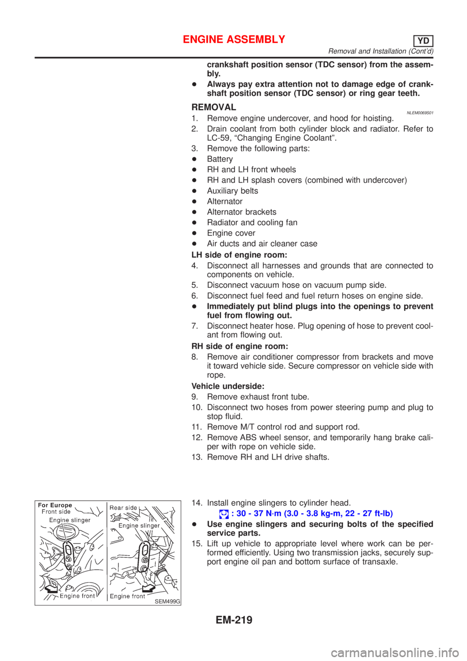
14. Install engine slingers to cylinder head.
: 30 - 37 N´m (3.0 - 3.8 kg-m, 22 - 27 ft-lb)
+Use engine slingers and securing bolts of the specified
service parts.
15. Lift up vehicle to appropriate level where work can be per-
formed efficiently. Using two transmission jacks, securely sup-
port engine oil pan and bottom surface of transaxle.
ENGINE ASSEMBLYYD
Removal and Installation (Cont'd)
EM-219
Page 2479 of 3051
Removal and InstallationNLEM0071CAUTION:
+When installing bearings, pistons, or other sliding parts,
lubricate contacting surfaces with new engine oil.
+Place removed parts such as bearings and bearing caps
in their proper order and direction.
+When installing connecting rod nuts, and main bearing
cap bolts, apply new engine oil to threads and seating
surfaces.
+Do not allow any magnetic materials to contact the signal
plate of flywheel.
+Do not remove the signal plate at back.
+Do not place the signal plate side facing under.
+Handle with care so as not to damage the signal plate
[especially four places on protrusions for signal of crank
position sensor (TDC sensor)].
DisassemblyNLEM0072PISTON AND CRANKSHAFTNLEM0072S011. Remove engine. Refer to ªENGINE ASSEMBLYº, ªRemoval
and Installationº, EM-218.
2. Place engine on a work stand.
a. Remove flywheel.
+Hold ring gear with ring gear stopper (KV10105630,
KV10105610). Then, loosen securing bolts with TORX socket
(size: Q8 E20, Commercial Service Tool) and remove them.
As an alternative method, hold the crankshaft pulley with a
pulley holder (SST) to remove the flywheel.
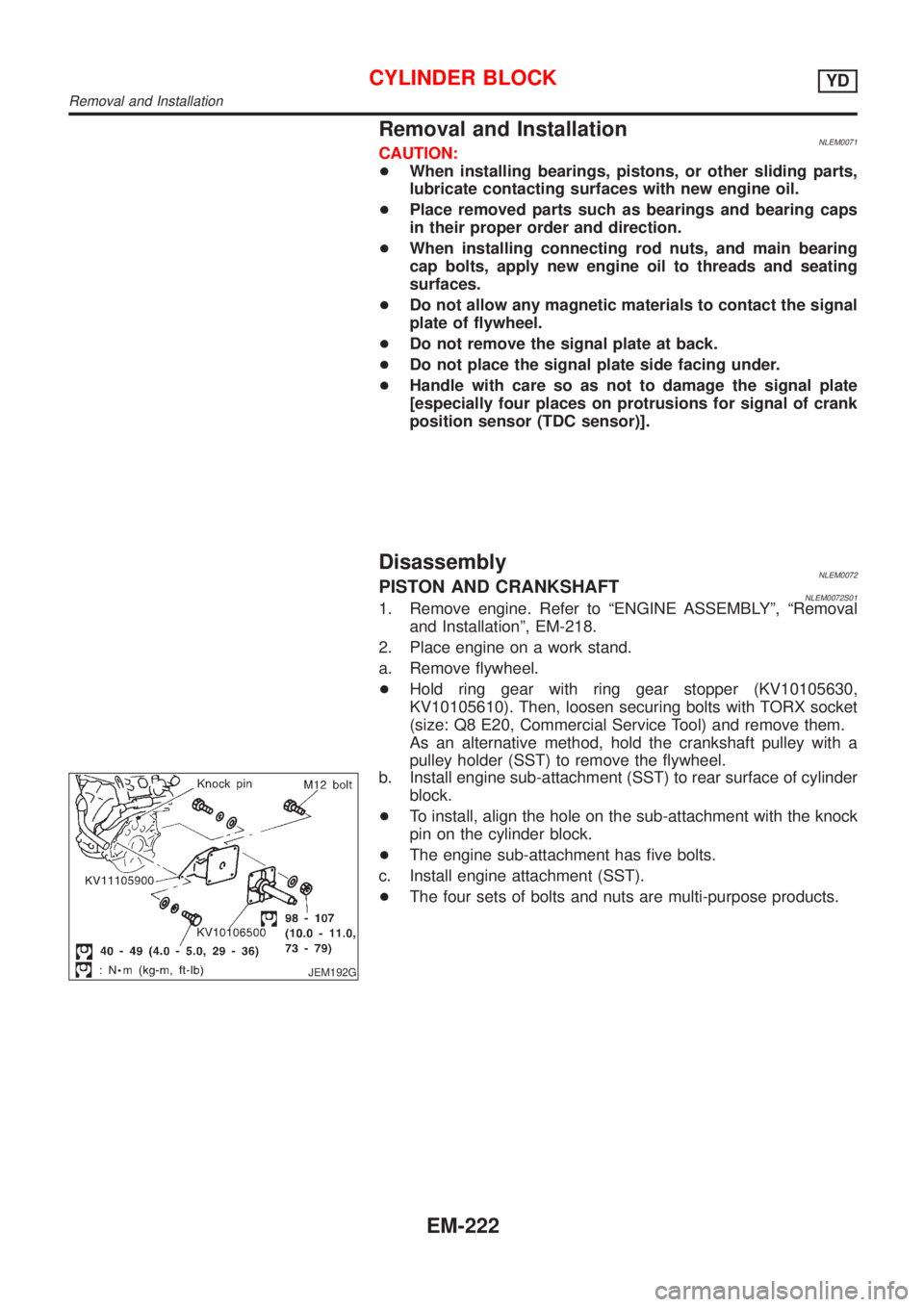
JEM192G
b. Install engine sub-attachment (SST) to rear surface of cylinder
block.
+To install, align the hole on the sub-attachment with the knock
pin on the cylinder block.
+The engine sub-attachment has five bolts.
c. Install engine attachment (SST).
+The four sets of bolts and nuts are multi-purpose products.
CYLINDER BLOCKYD
Removal and Installation
EM-222