2001 NISSAN ALMERA TINO wheel
[x] Cancel search: wheelPage 2168 of 3051
Possible cause:
Ð: Vehicle running ---: IndicationDrive condition Service procedure
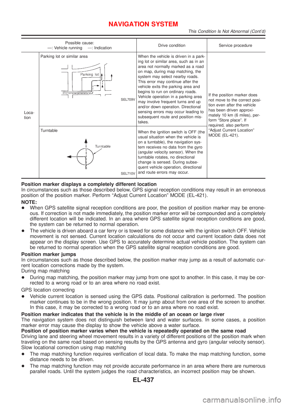
Loca-
tionParking lot or similar area
SEL709V
When the vehicle is driven in a park-
ing lot or similar area, such as in an
area not normally marked as a road
on map, during map matching, the
system may select nearby roads.
This error may continue after the
vehicle exits the parking area and
begins to run on ordinary roads.
Vehicle operation in a parking area
may involve frequent turns and up
and/or down operation. Directional
sensing errors may occur leading to
subsequent route and position mis-
takes.If the position marker does
not move to the correct posi-
tion even after the vehicle
has been driven approxi-
mately 10 km (6 miles), per-
form ªStore placeº. If
required, also perform
ªAdjust Current Locationº
MODE (EL-421). Turntable
SEL710V
When the ignition switch is OFF (the
usual situation when the vehicle is
on a turntable), the navigation sys-
tem receives no data from the gyro
(angular velocity sensor). When the
turntable rotates, no directional
change is sensed. During subse-
quent vehicle operation, directional
and route errors may occur.
Position marker displays a completely different location
In circumstances such as those described below, GPS signal reception conditions may result in an erroneous
position of the position marker. Perform ªAdjust Current Locationº MODE (EL-421).
NOTE:
+When GPS satellite signal reception conditions are poor, the position of position marker may be errone-
ous. If correction is not made immediately, the position marker error will be compounded and a completely
different location will be indicated. In an area where GPS satellite signal reception conditions are good,
the system can be returned to normal operation.
+The vehicle is driven aboard a car ferry or is towed for some distance with the ignition switch OFF. Vehicle
movement is not sensed. Current location calculations do not occur and current location data does not
appear on the display screen. Use GPS to accurately determine actual vehicle position. The system can
be returned to normal operation when the GPS satellite signal reception conditions are good.
Position marker jumps
In circumstances such as those described below, the position marker may jump as a result of automatic cur-
rent location corrections made by the system.
During map matching
+During map matching, the position marker may jump from one spot to another. In this case, it may be cor-
rected to a wrong road or to an area where no road exist.
GPS location correcting
+Vehicle current location is sensed using the GPS data. Positional calibration is performed. The position
marker continues to be in the wrong position. It may jump about from one area of the screen to another.
In this case, it may be corrected to a wrong road or to an area where no road exist.
Position marker indicates that the vehicle is in the middle of an ocean or large river
The navigation system does not distinguish between land and water surfaces. In some cases, a position
marker error may cause the display to show the vehicle above a water surface.
Position of position marker varies when the vehicle is repeatedly operated on the same road
Driving lane and steering wheel movement results in a variety of different positions of the position mark when
traveling on the same road based on sensing results by the GPS antenna and gyro (angular velocity sensor).
Slow locational correction using map matching
+The map matching function requires verification of local data. To make the map matching function, some
distance needs to be driven.
+The map matching function may not provide accurate performance in an area where there are numerous
parallel roads. Until the system judges the road characteristics, an incorrect position may be shown.
NAVIGATION SYSTEM
This Condition Is Not Abnormal (Cont'd)
EL-437
Page 2259 of 3051
REPLACEMENT OF CONNECTING ROD
BUSHING (SMALL END)
..........................................60
FLYWHEEL RUNOUT..............................................60
Assembly ...................................................................60
PISTON..................................................................60
CRANKSHAFT.........................................................61
SERVICE DATA AND SPECIFICATIONS (SDS).........64
General Specifications ...............................................64
Compression Pressure ..............................................64
Belt Deflection............................................................64
Spark Plug .................................................................65
Cylinder Head ............................................................65
Valve ..........................................................................65
VALVE....................................................................65
VALVE SPRING.......................................................65
VALVE LIFTER........................................................66
VALVE CLEARANCE................................................67
VALVE GUIDE.........................................................67
AVAILABLE SHIMS..................................................67
VALVE SEAT...........................................................70
VALVE SEAT RESURFACE LIMIT.............................71
Camshaft and Camshaft Bearing ..............................71
Cylinder Block ............................................................72
Piston, Piston Ring and Piston Pin ...........................73
PISTON..................................................................73
PISTON RING.........................................................73
PISTON PIN............................................................73
Connecting Rod .........................................................74
Crankshaft..................................................................74
Main Bearing..............................................................74
STANDARD.............................................................74
UNDERSIZE............................................................74
Connecting Rod Bearing ...........................................75
STANDARD SIZE....................................................75
UNDERSIZE............................................................75
Bearing Clearance .....................................................75
Miscellaneous Components.......................................75
SR
PRECAUTIONS.............................................................76
Parts Requiring Angular Tightening ...........................76
Liquid Gasket Application Procedure ........................76
PREPARATION.............................................................77
Special Service Tools ................................................77
Commercial Service Tools .........................................79
NOISE, VIBRATION AND HARSHNESS (NVH)
TROUBLESHOOTING...................................................80
NVH Troubleshooting - Engine Noise .......................81
OUTER COMPONENT PARTS.....................................82
Removal and Installation ...........................................82
MEASUREMENT OF COMPRESSION PRESSURE....85
DRIVE BELTS................................................................86
Checking ....................................................................86AIR CLEANER...............................................................88
Changing Air Cleaner Filter .......................................88
VISCOUS PAPER TYPE...........................................88
SPARK PLUG................................................................89
Checking and Changing Spark Plugs .......................89
Checking Ignition Leads ............................................90
OIL PAN.........................................................................91
Components...............................................................91
Removal .....................................................................91
Installation ..................................................................93
TIMING CHAIN..............................................................96
Components...............................................................96
Removal .....................................................................97
Inspection.................................................................100
Installation ................................................................100
OIL SEAL.....................................................................105
Replacement ............................................................105
VALVE OIL SEAL...................................................105
FRONT OIL SEAL..................................................105
REAR OIL SEAL....................................................107
CYLINDER HEAD........................................................108
Components.............................................................108
Removal ...................................................................109
Disassembly............................................................. 111
Inspection................................................................. 113
CYLINDER HEAD DISTORTION............................. 113
CAMSHAFT VISUAL CHECK.................................. 114
CAMSHAFT RUNOUT............................................ 114
CAMSHAFT CAM HEIGHT..................................... 114
CAMSHAFT JOURNAL CLEARANCE...................... 115
CAMSHAFT END PLAY.......................................... 115
CAMSHAFT SPROCKET RUNOUT......................... 116
VALVE GUIDE CLEARANCE.................................. 116
VALVE GUIDE REPLACEMENT.............................. 116
VALVE SEATS....................................................... 117
REPLACING VALVE SEAT FOR SERVICE PARTS.. 118
VALVE DIMENSIONS............................................. 119
VALVE SPRING..................................................... 119
HYDRAULIC LASH ADJUSTER.............................. 119
ROCKER ARM, SHIM AND ROCKER ARM GUIDE...120
Assembly .................................................................120
Installation ................................................................123
ENGINE ASSEMBLY...................................................130
Removal and Installation .........................................130
REMOVAL.............................................................131
INSTALLATION......................................................132
CYLINDER BLOCK.....................................................133
Components.............................................................133
Removal and Installation .........................................134
Disassembly.............................................................134
PISTON AND CRANKSHAFT..................................134
Inspection.................................................................134
PISTON AND PISTON PIN CLEARANCE................134
PISTON RING SIDE CLEARANCE..........................135
CONTENTS(Cont'd)
EM-2
Page 2261 of 3051
Components.............................................................200
Removal ...................................................................201
PREPARATIVE WORK...........................................201
CAMSHAFT...........................................................201
CYLINDER HEAD..................................................202
Disassembly.............................................................202
Inspection.................................................................203
CYLINDER HEAD DISTORTION.............................203
CAMSHAFT VISUAL CHECK..................................204
CAMSHAFT RUNOUT............................................204
CAMSHAFT CAM HEIGHT.....................................204
CAMSHAFT JOURNAL CLEARANCE......................204
CAMSHAFT END PLAY..........................................205
CAMSHAFT SPROCKET RUNOUT.........................205
VALVE GUIDE CLEARANCE..................................205
VALVE GUIDE REPLACEMENT..............................206
VALVE SEATS.......................................................207
REPLACING VALVE SEAT FOR SERVICE PARTS..207
VALVE DIMENSIONS.............................................209
VALVE SPRING.....................................................209
VALVE LIFTER......................................................209
Assembly .................................................................210
Installation ................................................................210
CYLINDER HEAD GASKET SELECTION.................210
CYLINDER HEAD BOLT DEFORMATION CHECK... 211
CYLINDER HEAD-TO-BLOCK DIFFERENCE
CHECK
.................................................................212
LIQUID GASKET APPLICATION ON REAR CHAIN
CASE
....................................................................212
CYLINDER HEAD INSTALLATION..........................212
GLOW PLUG INSTALLATION.................................212
CAMSHAFT INSTALLATION...................................213
Valve Clearance.......................................................214
CHECKING...........................................................214
ADJUSTING..........................................................215
ENGINE ASSEMBLY...................................................218
Removal and Installation .........................................218
REMOVAL.............................................................219
INSTALLATION......................................................220
CYLINDER BLOCK.....................................................221
Components.............................................................221
Removal and Installation .........................................222
Disassembly.............................................................222
PISTON AND CRANKSHAFT..................................222
Inspection.................................................................225
CRANKSHAFT END PLAY.....................................225
CONNECTING ROD SIDE CLEARANCE.................225
PISTON AND PISTON PIN CLEARANCE................226
PISTON RING SIDE CLEARANCE..........................226
PISTON RING END GAP........................................226
CONNECTING ROD BEND AND TORSION.............227
CYLINDER BLOCK DISTORTION AND WEAR.........227
PISTON-TO-BORE CLEARANCE............................228
CRANKSHAFT.......................................................229
MAIN BEARING HOUSING INNER DIAMETER........230
BEARING CLEARANCE.........................................230
MAIN BEARING CRUSH HEIGHT...........................234
MAIN BEARING CAP BOLT DEFORMATION...........234
CONNECTING ROD BUSHING CLEARANCE
(SMALL END)
........................................................234
CONNECTING ROD BOLT DEFORMATION............235
FLYWHEEL RUNOUT............................................235
OIL JET................................................................235
OIL JET RELIEF VALVE.........................................235
Assembly .................................................................236
PISTON................................................................236
CRANKSHAFT.......................................................236
REPLACEMENT OF PILOT BUSHING.....................239
SERVICE DATA AND SPECIFICATIONS (SDS).......241
General Specifications .............................................241
Compression Pressure ............................................241
Belt Deflection..........................................................241
Cylinder Head ..........................................................241
Valve ........................................................................242
VALVE..................................................................242
VALVE CLEARANCE..............................................242
AVAILABLE SHIMS................................................242
VALVE SPRING.....................................................243
VALVE LIFTER......................................................243
VALVE GUIDE.......................................................244
Valve Seat................................................................245
Camshaft and Camshaft Bearing ............................247
Cylinder Block ..........................................................248
Piston, Piston Ring and Piston Pin .........................248
AVAILABLE PISTON..............................................248
PISTON RING.......................................................249
PISTON PIN..........................................................249
Connecting Rod .......................................................249
Crankshaft................................................................249
Available Main Bearing ............................................250
UNDERSIZE..........................................................250
Available Connecting Rod Bearing..........................250
CONNECTING ROD BEARING...............................250
UNDERSIZE..........................................................251
Miscellaneous Components.....................................251
BEARING CLEARANCE.........................................251
CONTENTS(Cont'd)
EM-4
Page 2280 of 3051
CAUTION:
+After removing timing chain, do not turn crankshaft and
camshaft separately, or valves will strike piston heads.
+When installing chain tensioner, oil seals, or other sliding
parts, lubricate contacting surfaces with new engine oil.
+Apply new engine oil to bolt threads and seat surfaces
when installing camshaft sprocket and crankshaft pulley.
+When removing oil pump assembly, remove camshaft
position sensor (PHASE), then remove timing chain from
engine.
+Be careful not to damage sensor edges.
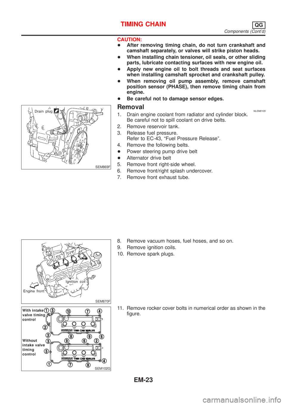
SEM869F
RemovalNLEM01051. Drain engine coolant from radiator and cylinder block.
Be careful not to spill coolant on drive belts.
2. Remove reservoir tank.
3. Release fuel pressure.
Refer to EC-43, ªFuel Pressure Releaseº.
4. Remove the following belts.
+Power steering pump drive belt
+Alternator drive belt
5. Remove front right-side wheel.
6. Remove front/right splash undercover.
7. Remove front exhaust tube.
SEM870F
8. Remove vacuum hoses, fuel hoses, and so on.
9. Remove ignition coils.
10. Remove spark plugs.
SEM102G
11. Remove rocker cover bolts in numerical order as shown in the
figure.
TIMING CHAINQG
Components (Cont'd)
EM-23
Page 2287 of 3051
SEM887F
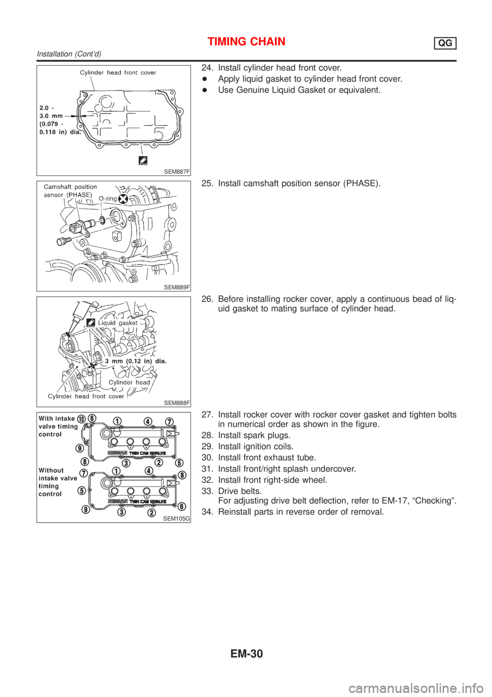
24. Install cylinder head front cover.
+Apply liquid gasket to cylinder head front cover.
+Use Genuine Liquid Gasket or equivalent.
SEM889F
25. Install camshaft position sensor (PHASE).
SEM888F
26. Before installing rocker cover, apply a continuous bead of liq-
uid gasket to mating surface of cylinder head.
SEM105G
27. Install rocker cover with rocker cover gasket and tighten bolts
in numerical order as shown in the figure.
28. Install spark plugs.
29. Install ignition coils.
30. Install front exhaust tube.
31. Install front/right splash undercover.
32. Install front right-side wheel.
33. Drive belts.
For adjusting drive belt deflection, refer to EM-17, ªCheckingº.
34. Reinstall parts in reverse order of removal.
TIMING CHAINQG
Installation (Cont'd)
EM-30
Page 2289 of 3051
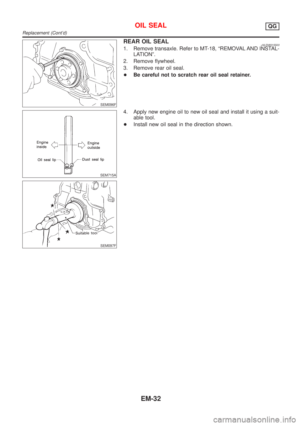
SEM096F
REAR OIL SEAL=NLEM0015S031. Remove transaxle. Refer to MT-18, ªREMOVAL AND INSTAL-
LATIONº.
2. Remove flywheel.
3. Remove rear oil seal.
+Be careful not to scratch rear oil seal retainer.
SEM715A
4. Apply new engine oil to new oil seal and install it using a suit-
able tool.
+Install new oil seal in the direction shown.
SEM097F
OIL SEALQG
Replacement (Cont'd)
EM-32
Page 2307 of 3051
WARNING:
+Position vehicle on a flat and solid surface.
+Place chocks at front and back of rear wheels.
+Do not remove engine until exhaust system has com-
pletely cooled off, otherwise, you may burn yourself
and/or fire may break out in fuel line.
+Before disconnecting fuel hose, release pressure.
Refer to EC-43, ªFuel Pressure Releaseº.
+Be sure to lift engine and transaxle in a safe manner.
+For engines not equipped with engine slingers, attach
proper slingers and bolts described in PARTS CATALOG.
CAUTION:
+When lifting engine, be sure to clear surrounding parts.
Use special care near accelerator wire casing, brake lines
and brake master cylinder.
+When lifting the engine, always use engine slingers in a
safe manner.
+When removing drive shaft, be careful not to damage
grease seal of transaxle.
+Before separating engine and transaxle, remove crank-
shaft position sensor (POS) from the cylinder block
assembly.
+Always be extra careful not to damage edge of crankshaft
position sensor (POS), or signal plate teeth.
Engine cannot be removed separately from transaxle. Remove
engine with transaxle as an assembly.
REMOVALNLEM0022S011. Drain coolant from radiator and cylinder block. Refer to LC-18,
ªChanging Engine Coolantº.
2. Remove coolant reservoir tank and bracket.
3. Drain engine oil.
4. Remove battery and battery tray.
5. Remove air cleaner and air duct.
6. Remove drive belts.
7. Remove alternator and air conditioner compressor from
engine.
8. Remove power steering oil pump from engine and position
aside.
Power steering oil pump does not need to be disconnected
from power steering tubes.
ENGINE ASSEMBLYQG
Removal and Installation (Cont'd)
EM-50
Page 2309 of 3051
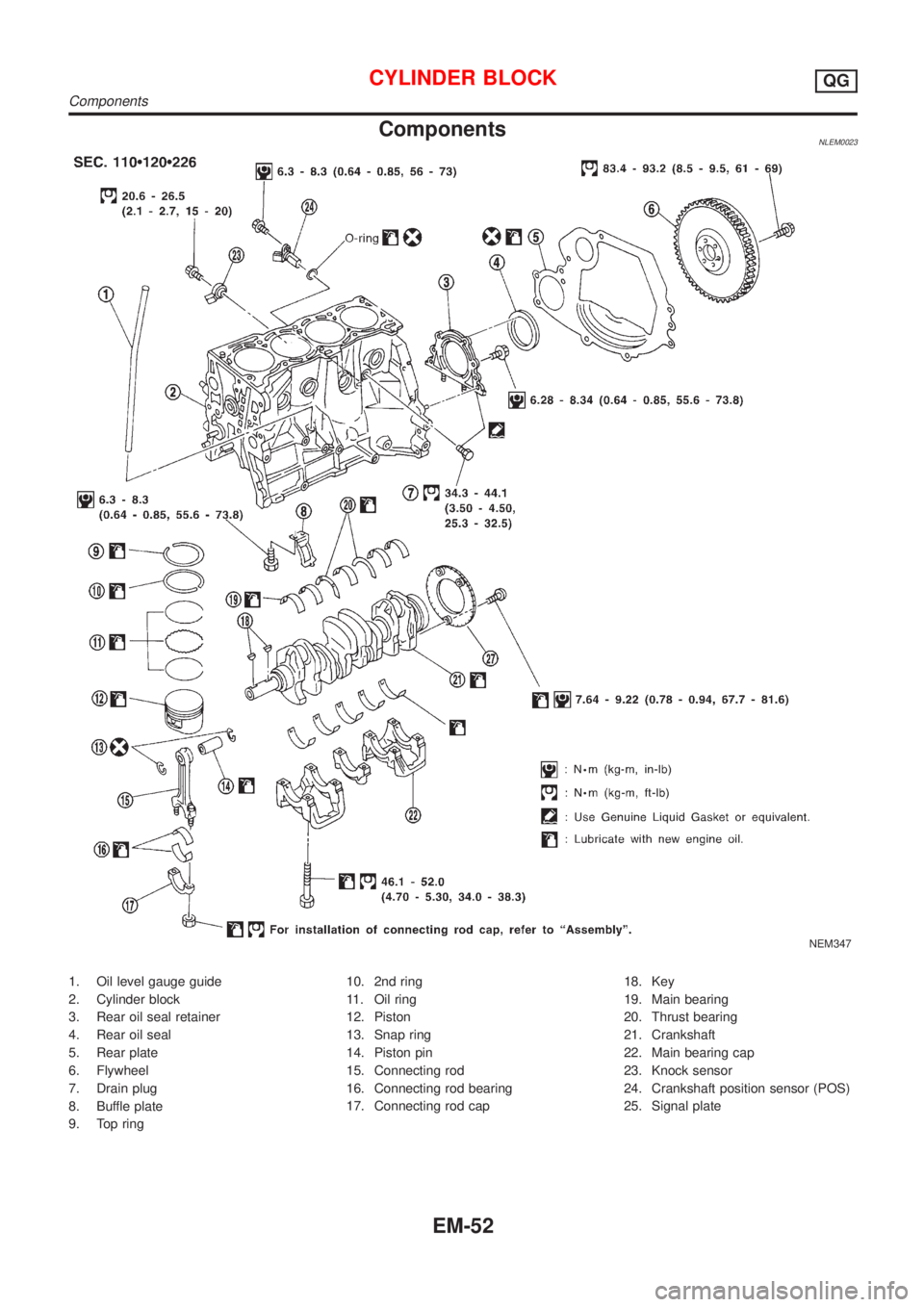
ComponentsNLEM0023
NEM347
1. Oil level gauge guide
2. Cylinder block
3. Rear oil seal retainer
4. Rear oil seal
5. Rear plate
6. Flywheel
7. Drain plug
8. Buffle plate
9. Top ring10. 2nd ring
11. Oil ring
12. Piston
13. Snap ring
14. Piston pin
15. Connecting rod
16. Connecting rod bearing
17. Connecting rod cap18. Key
19. Main bearing
20. Thrust bearing
21. Crankshaft
22. Main bearing cap
23. Knock sensor
24. Crankshaft position sensor (POS)
25. Signal plate
CYLINDER BLOCKQG
Components
EM-52