2001 NISSAN ALMERA TINO wheel
[x] Cancel search: wheelPage 1671 of 3051
SEF437Y
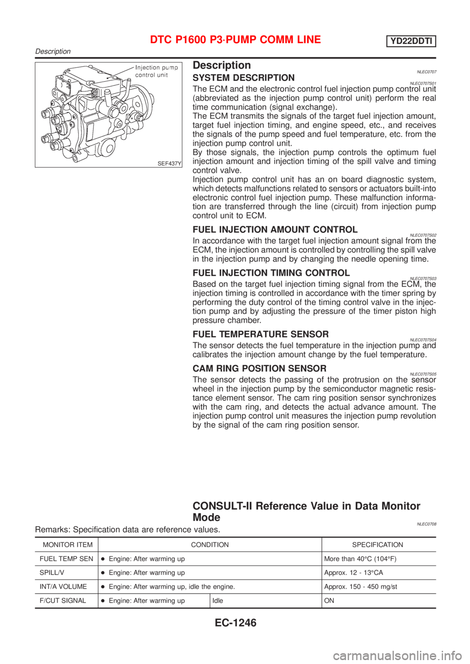
DescriptionNLEC0707SYSTEM DESCRIPTIONNLEC0707S01The ECM and the electronic control fuel injection pump control unit
(abbreviated as the injection pump control unit) perform the real
time communication (signal exchange).
The ECM transmits the signals of the target fuel injection amount,
target fuel injection timing, and engine speed, etc., and receives
the signals of the pump speed and fuel temperature, etc. from the
injection pump control unit.
By those signals, the injection pump controls the optimum fuel
injection amount and injection timing of the spill valve and timing
control valve.
Injection pump control unit has an on board diagnostic system,
which detects malfunctions related to sensors or actuators built-into
electronic control fuel injection pump. These malfunction informa-
tion are transferred through the line (circuit) from injection pump
control unit to ECM.
FUEL INJECTION AMOUNT CONTROLNLEC0707S02In accordance with the target fuel injection amount signal from the
ECM, the injection amount is controlled by controlling the spill valve
in the injection pump and by changing the needle opening time.
FUEL INJECTION TIMING CONTROLNLEC0707S03Based on the target fuel injection timing signal from the ECM, the
injection timing is controlled in accordance with the timer spring by
performing the duty control of the timing control valve in the injec-
tion pump and by adjusting the pressure of the timer piston high
pressure chamber.
FUEL TEMPERATURE SENSORNLEC0707S04The sensor detects the fuel temperature in the injection pump and
calibrates the injection amount change by the fuel temperature.
CAM RING POSITION SENSORNLEC0707S05The sensor detects the passing of the protrusion on the sensor
wheel in the injection pump by the semiconductor magnetic resis-
tance element sensor. The cam ring position sensor synchronizes
with the cam ring, and detects the actual advance amount. The
injection pump control unit measures the injection pump revolution
by the signal of the cam ring position sensor.
CONSULT-II Reference Value in Data Monitor
Mode
NLEC0708Remarks: Specification data are reference values.
MONITOR ITEM CONDITION SPECIFICATION
FUEL TEMP SEN+Engine: After warming up More than 40ÉC (104ÉF)
SPILL/V+Engine: After warming up Approx. 12 - 13ÉCA
INT/A VOLUME+Engine: After warming up, idle the engine. Approx. 150 - 450 mg/st
F/CUT SIGNAL+Engine: After warming up Idle ON
DTC P1600 P3´PUMP COMM LINEYD22DDTI
Description
EC-1246
Page 1689 of 3051
SEF437Y
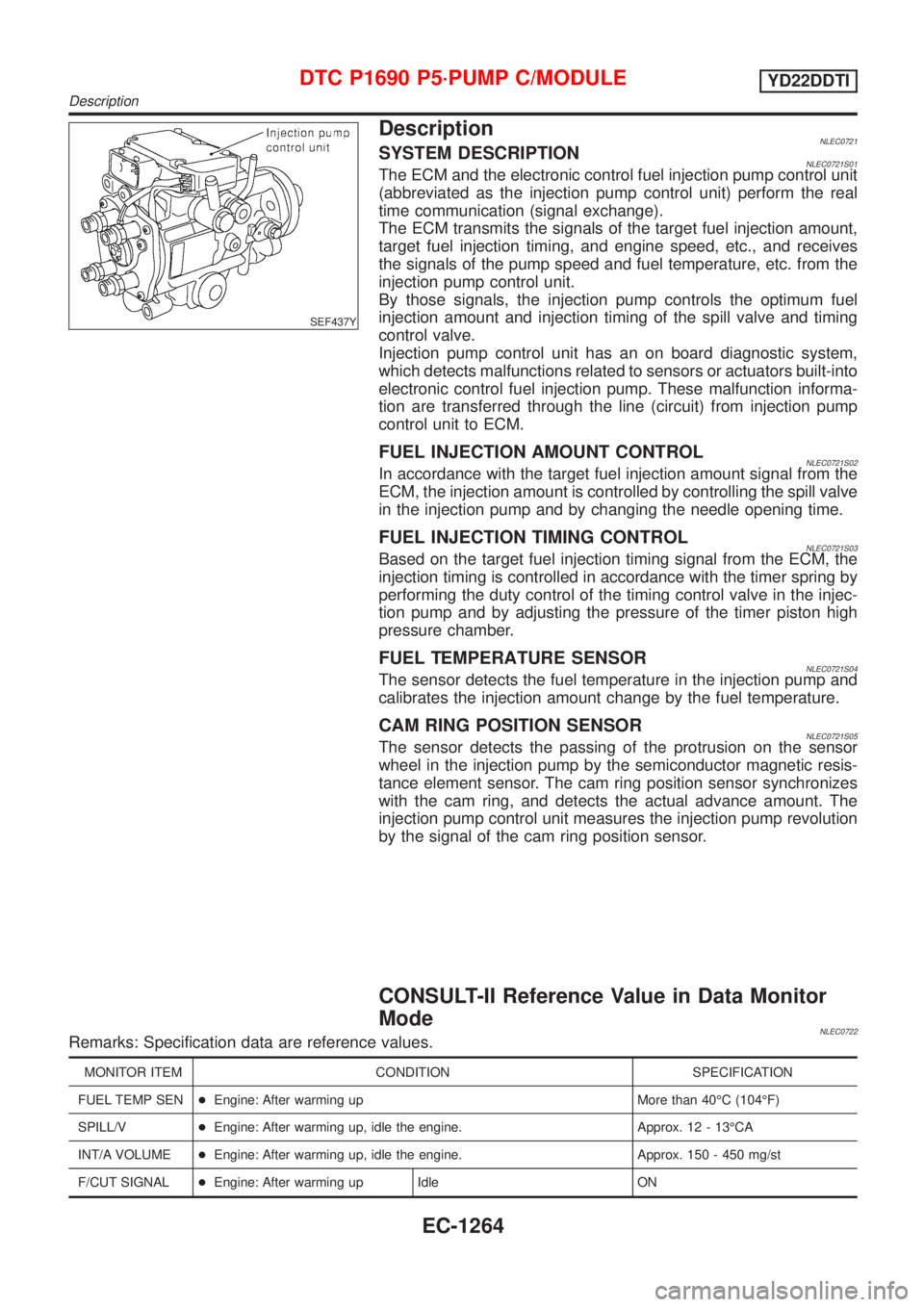
DescriptionNLEC0721SYSTEM DESCRIPTIONNLEC0721S01The ECM and the electronic control fuel injection pump control unit
(abbreviated as the injection pump control unit) perform the real
time communication (signal exchange).
The ECM transmits the signals of the target fuel injection amount,
target fuel injection timing, and engine speed, etc., and receives
the signals of the pump speed and fuel temperature, etc. from the
injection pump control unit.
By those signals, the injection pump controls the optimum fuel
injection amount and injection timing of the spill valve and timing
control valve.
Injection pump control unit has an on board diagnostic system,
which detects malfunctions related to sensors or actuators built-into
electronic control fuel injection pump. These malfunction informa-
tion are transferred through the line (circuit) from injection pump
control unit to ECM.
FUEL INJECTION AMOUNT CONTROLNLEC0721S02In accordance with the target fuel injection amount signal from the
ECM, the injection amount is controlled by controlling the spill valve
in the injection pump and by changing the needle opening time.
FUEL INJECTION TIMING CONTROLNLEC0721S03Based on the target fuel injection timing signal from the ECM, the
injection timing is controlled in accordance with the timer spring by
performing the duty control of the timing control valve in the injec-
tion pump and by adjusting the pressure of the timer piston high
pressure chamber.
FUEL TEMPERATURE SENSORNLEC0721S04The sensor detects the fuel temperature in the injection pump and
calibrates the injection amount change by the fuel temperature.
CAM RING POSITION SENSORNLEC0721S05The sensor detects the passing of the protrusion on the sensor
wheel in the injection pump by the semiconductor magnetic resis-
tance element sensor. The cam ring position sensor synchronizes
with the cam ring, and detects the actual advance amount. The
injection pump control unit measures the injection pump revolution
by the signal of the cam ring position sensor.
CONSULT-II Reference Value in Data Monitor
Mode
NLEC0722Remarks: Specification data are reference values.
MONITOR ITEM CONDITION SPECIFICATION
FUEL TEMP SEN+Engine: After warming up More than 40ÉC (104ÉF)
SPILL/V+Engine: After warming up, idle the engine. Approx. 12 - 13ÉCA
INT/A VOLUME+Engine: After warming up, idle the engine. Approx. 150 - 450 mg/st
F/CUT SIGNAL+Engine: After warming up Idle ON
DTC P1690 P5´PUMP C/MODULEYD22DDTI
Description
EC-1264
Page 1735 of 3051
Supplemental Restraint System (SRS) ªAIR
BAGº and ªSEAT BELT PRE-TENSIONERº
NLEL0001The Supplemental Restraint System such as ªAIR BAGº and ªSEAT BELT PRE-TENSIONERº used along with
a seat belt, helps to reduce the risk or severity of injury to the driver and front passenger for certain types of
collision. The SRS system composition which is available to NISSAN MODEL V10 is as follows (The compo-
sition varies according to the destination and optional equipment.):
+For a frontal collision
The Supplemental Restraint System consists of driver air bag module (located in the center of the steer-
ing wheel), front passenger air bag module (located on the instrument panel on passenger side), front seat
belt pre-tensioners, a diagnosis sensor unit, warning lamp, wiring harness and spiral cable.
+For a side collision
The Supplemental Restraint System consists of front side air bag module (located in the outer side of front
seat), side air bag (satellite) sensor, diagnosis sensor unit (one of components of air bags for a frontal
collision), wiring harness, warning lamp (one of components of air bags for a frontal collision).
Information necessary to service the system safely is included in theRS sectionof this Service Manual.
WARNING:
+To avoid rendering the SRS inoperative, which could increase the risk of personal injury or death
in the event of a collision which would result in air bag inflation, all maintenance should be per-
formed by an authorized NISSAN dealer.
+Improper maintenance, including incorrect removal and installation of the SRS, can lead to per-
sonal injury caused by unintentional activation of the system. For removal of Spiral Cable and Air
Bag Module, see the RS section.
+Do not use electrical test equipment on any circuit related to the SRS unless instructed to in this
Service Manual. Spiral cable and wiring harnesses covered with yellow insulation tape either just
before the harness connectors or for the complete harness are related to the SRS.
Wiring Diagrams and Trouble DiagnosisNLEL0002When you read wiring diagrams, refer to the following:
+Refer to GI-11, ªHOW TO READ WIRING DIAGRAMSº
+Refer to EL-10, ªPOWER SUPPLY ROUTINGº for power distribution circuit
When you perform trouble diagnosis, refer to the following:
+Refer to GI-32, ªHOW TO FOLLOW TEST GROUP IN TROUBLE DIAGNOSISº
+Refer to GI-21, ªHOW TO PERFORM EFFICIENT DIAGNOSIS FOR AN ELECTRICAL INCIDENTº
Check for any Service bulletins before servicing the vehicle.
PRECAUTIONS
Supplemental Restraint System (SRS) ªAIR BAGº and ªSEAT BELT PRE-TENSIONERº
EL-4
Page 1797 of 3051

CEL501
ReplacementNLEL0010For removal and installation of spiral cable, refer to RS-24
ªInstallation Ð Air Bag Module and Spiral Cableº.
+Each switch can be replaced without removing combination
switch base.
CEL406
+To remove combination switch base, remove base attaching
screw.
SEL151V
+Before installing the steering wheel, align the steering wheel
guide pins with the screws which secure the combination
switch as shown in the left figure.
COMBINATION SWITCH
Replacement
EL-66
Page 2101 of 3051
PrecautionsNLEL0510WARNING:
Do not attempt to disassemble the monitor. Parts of the monitor have high voltages that can result in
severe and dangerous electric shock.
CAUTION:
+Do not reverse battery connections.
+Do not attach unauthorized parts.
+Protect the unit from severe impact.
NOTE:
Before beginning repair, determine whether or not the unit is defective. Refer to ªThis Condition Is Not
Abnormalº (EL-432).
Component Parts LocationNLEL0511For details, refer to ªELECTRICAL UNIT LAYOUTº (EL-442) and ªHARNESS LAYOUTº (EL-452).
SEL504X
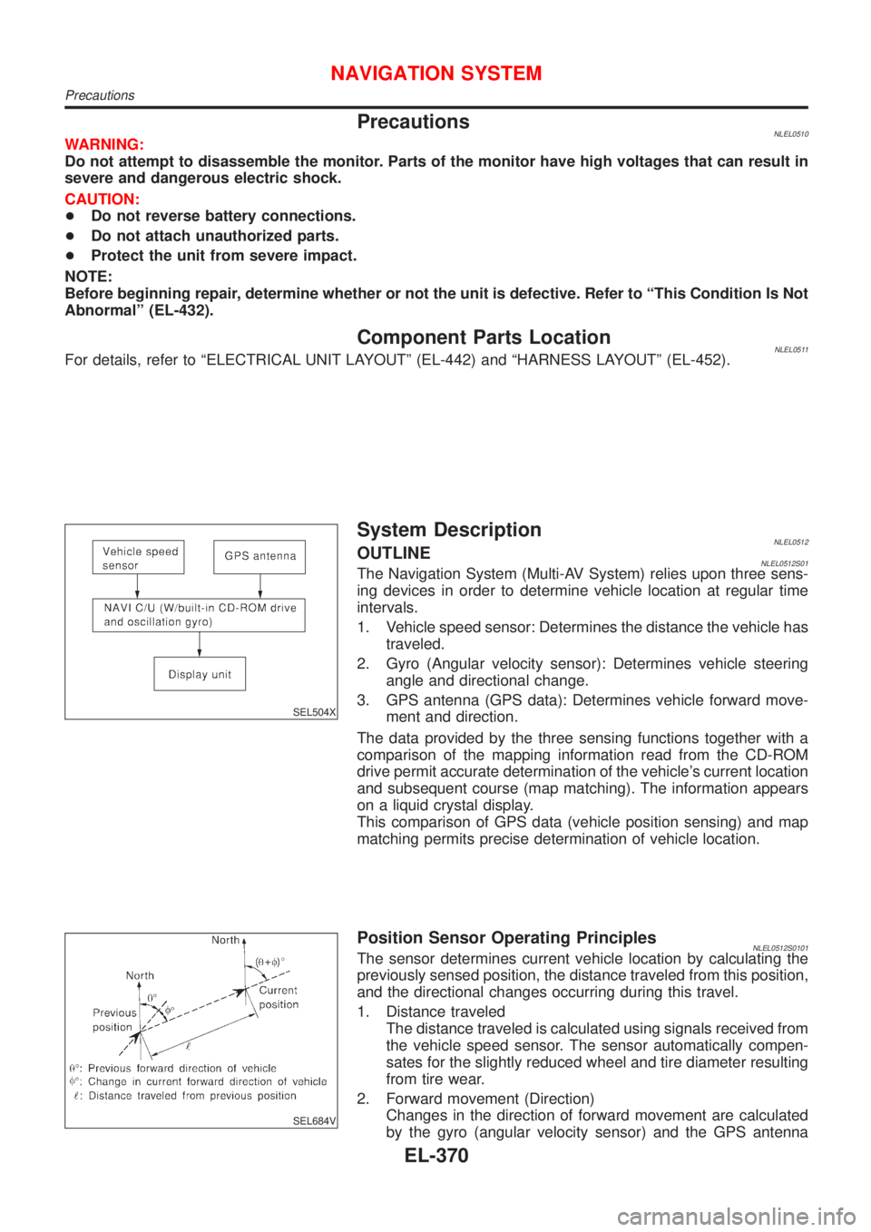
System DescriptionNLEL0512OUTLINENLEL0512S01The Navigation System (Multi-AV System) relies upon three sens-
ing devices in order to determine vehicle location at regular time
intervals.
1. Vehicle speed sensor: Determines the distance the vehicle has
traveled.
2. Gyro (Angular velocity sensor): Determines vehicle steering
angle and directional change.
3. GPS antenna (GPS data): Determines vehicle forward move-
ment and direction.
The data provided by the three sensing functions together with a
comparison of the mapping information read from the CD-ROM
drive permit accurate determination of the vehicle's current location
and subsequent course (map matching). The information appears
on a liquid crystal display.
This comparison of GPS data (vehicle position sensing) and map
matching permits precise determination of vehicle location.
SEL684V
Position Sensor Operating PrinciplesNLEL0512S0101The sensor determines current vehicle location by calculating the
previously sensed position, the distance traveled from this position,
and the directional changes occurring during this travel.
1. Distance traveled
The distance traveled is calculated using signals received from
the vehicle speed sensor. The sensor automatically compen-
sates for the slightly reduced wheel and tire diameter resulting
from tire wear.
2. Forward movement (Direction)
Changes in the direction of forward movement are calculated
by the gyro (angular velocity sensor) and the GPS antenna
NAVIGATION SYSTEM
Precautions
EL-370
Page 2132 of 3051
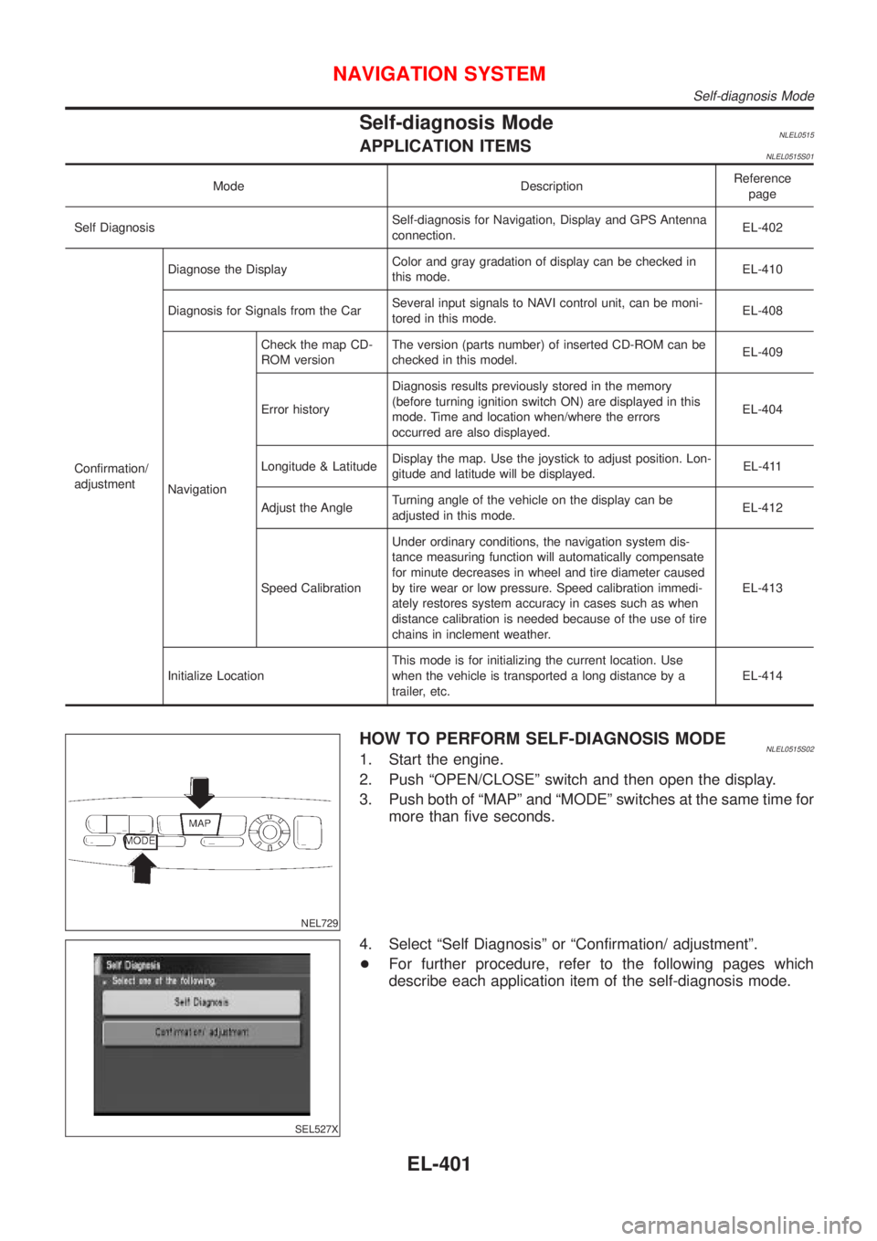
Self-diagnosis ModeNLEL0515APPLICATION ITEMSNLEL0515S01
Mode DescriptionReference
page
Self DiagnosisSelf-diagnosis for Navigation, Display and GPS Antenna
connection.EL-402
Confirmation/
adjustmentDiagnose the DisplayColor and gray gradation of display can be checked in
this mode.EL-410
Diagnosis for Signals from the CarSeveral input signals to NAVI control unit, can be moni-
tored in this mode.EL-408
NavigationCheck the map CD-
ROM versionThe version (parts number) of inserted CD-ROM can be
checked in this model.EL-409
Error historyDiagnosis results previously stored in the memory
(before turning ignition switch ON) are displayed in this
mode. Time and location when/where the errors
occurred are also displayed.EL-404
Longitude & LatitudeDisplay the map. Use the joystick to adjust position. Lon-
gitude and latitude will be displayed.EL-411
Adjust the AngleTurning angle of the vehicle on the display can be
adjusted in this mode.EL-412
Speed CalibrationUnder ordinary conditions, the navigation system dis-
tance measuring function will automatically compensate
for minute decreases in wheel and tire diameter caused
by tire wear or low pressure. Speed calibration immedi-
ately restores system accuracy in cases such as when
distance calibration is needed because of the use of tire
chains in inclement weather.EL-413
Initialize LocationThis mode is for initializing the current location. Use
when the vehicle is transported a long distance by a
trailer, etc.EL-414
NEL729
HOW TO PERFORM SELF-DIAGNOSIS MODENLEL0515S021. Start the engine.
2. Push ªOPEN/CLOSEº switch and then open the display.
3. Push both of ªMAPº and ªMODEº switches at the same time for
more than five seconds.
SEL527X
4. Select ªSelf Diagnosisº or ªConfirmation/ adjustmentº.
+For further procedure, refer to the following pages which
describe each application item of the self-diagnosis mode.
NAVIGATION SYSTEM
Self-diagnosis Mode
EL-401
Page 2165 of 3051
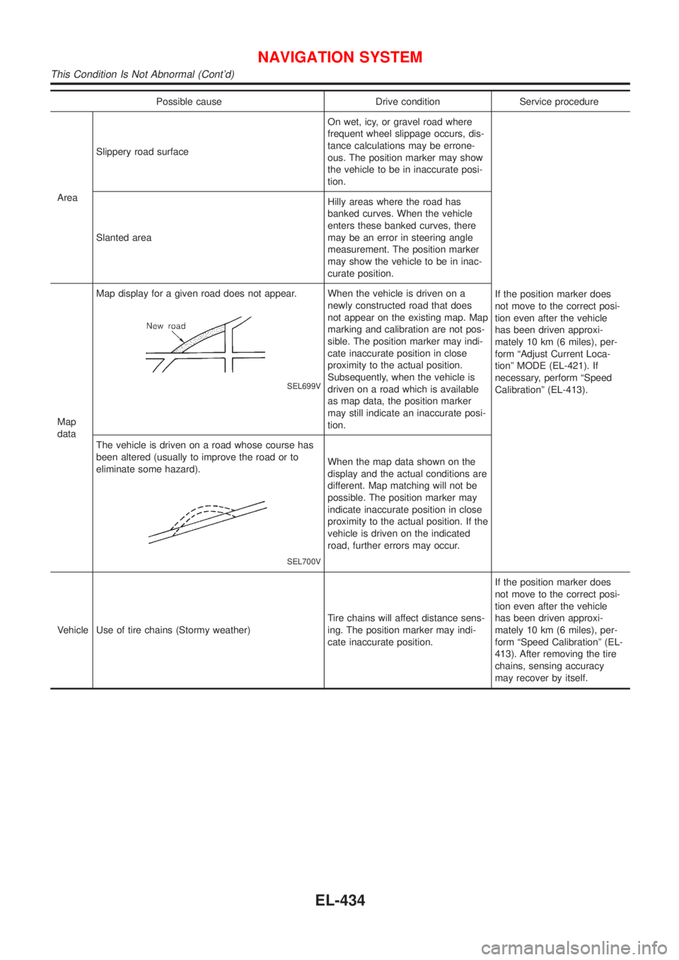
Possible cause Drive condition Service procedure
AreaSlippery road surfaceOn wet, icy, or gravel road where
frequent wheel slippage occurs, dis-
tance calculations may be errone-
ous. The position marker may show
the vehicle to be in inaccurate posi-
tion.
If the position marker does
not move to the correct posi-
tion even after the vehicle
has been driven approxi-
mately 10 km (6 miles), per-
form ªAdjust Current Loca-
tionº MODE (EL-421). If
necessary, perform ªSpeed
Calibrationº (EL-413). Slanted areaHilly areas where the road has
banked curves. When the vehicle
enters these banked curves, there
may be an error in steering angle
measurement. The position marker
may show the vehicle to be in inac-
curate position.
Map
dataMap display for a given road does not appear.
SEL699V
When the vehicle is driven on a
newly constructed road that does
not appear on the existing map. Map
marking and calibration are not pos-
sible. The position marker may indi-
cate inaccurate position in close
proximity to the actual position.
Subsequently, when the vehicle is
driven on a road which is available
as map data, the position marker
may still indicate an inaccurate posi-
tion.
The vehicle is driven on a road whose course has
been altered (usually to improve the road or to
eliminate some hazard).
SEL700V
When the map data shown on the
display and the actual conditions are
different. Map matching will not be
possible. The position marker may
indicate inaccurate position in close
proximity to the actual position. If the
vehicle is driven on the indicated
road, further errors may occur.
Vehicle Use of tire chains (Stormy weather)Tire chains will affect distance sens-
ing. The position marker may indi-
cate inaccurate position.If the position marker does
not move to the correct posi-
tion even after the vehicle
has been driven approxi-
mately 10 km (6 miles), per-
form ªSpeed Calibrationº (EL-
413). After removing the tire
chains, sensing accuracy
may recover by itself.
NAVIGATION SYSTEM
This Condition Is Not Abnormal (Cont'd)
EL-434
Page 2166 of 3051
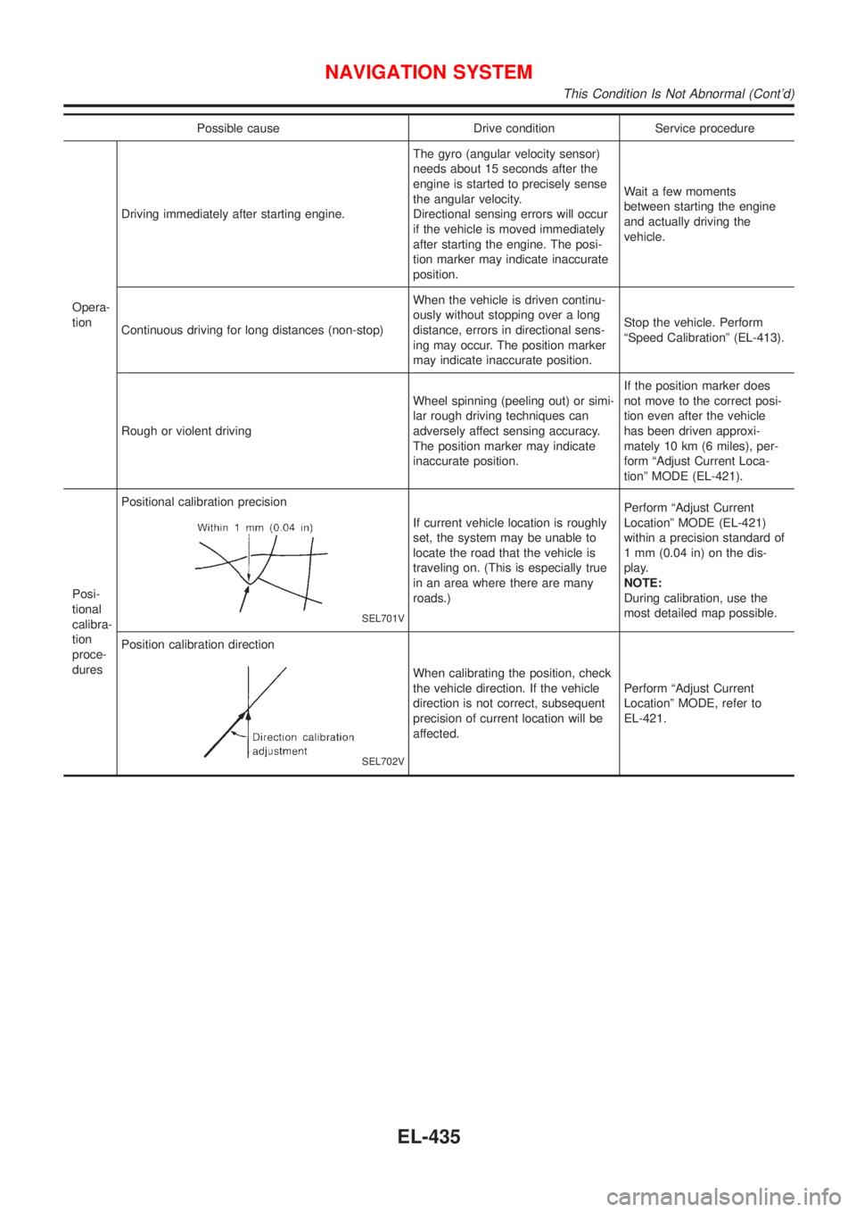
Possible cause Drive condition Service procedure
Opera-
tionDriving immediately after starting engine.The gyro (angular velocity sensor)
needs about 15 seconds after the
engine is started to precisely sense
the angular velocity.
Directional sensing errors will occur
if the vehicle is moved immediately
after starting the engine. The posi-
tion marker may indicate inaccurate
position.Wait a few moments
between starting the engine
and actually driving the
vehicle.
Continuous driving for long distances (non-stop)When the vehicle is driven continu-
ously without stopping over a long
distance, errors in directional sens-
ing may occur. The position marker
may indicate inaccurate position.Stop the vehicle. Perform
ªSpeed Calibrationº (EL-413).
Rough or violent drivingWheel spinning (peeling out) or simi-
lar rough driving techniques can
adversely affect sensing accuracy.
The position marker may indicate
inaccurate position.If the position marker does
not move to the correct posi-
tion even after the vehicle
has been driven approxi-
mately 10 km (6 miles), per-
form ªAdjust Current Loca-
tionº MODE (EL-421).
Posi-
tional
calibra-
tion
proce-
duresPositional calibration precision
SEL701V
If current vehicle location is roughly
set, the system may be unable to
locate the road that the vehicle is
traveling on. (This is especially true
in an area where there are many
roads.)Perform ªAdjust Current
Locationº MODE (EL-421)
within a precision standard of
1 mm (0.04 in) on the dis-
play.
NOTE:
During calibration, use the
most detailed map possible.
Position calibration direction
SEL702V
When calibrating the position, check
the vehicle direction. If the vehicle
direction is not correct, subsequent
precision of current location will be
affected.Perform ªAdjust Current
Locationº MODE, refer to
EL-421.
NAVIGATION SYSTEM
This Condition Is Not Abnormal (Cont'd)
EL-435