2001 NISSAN ALMERA stop start
[x] Cancel search: stop startPage 1357 of 2898
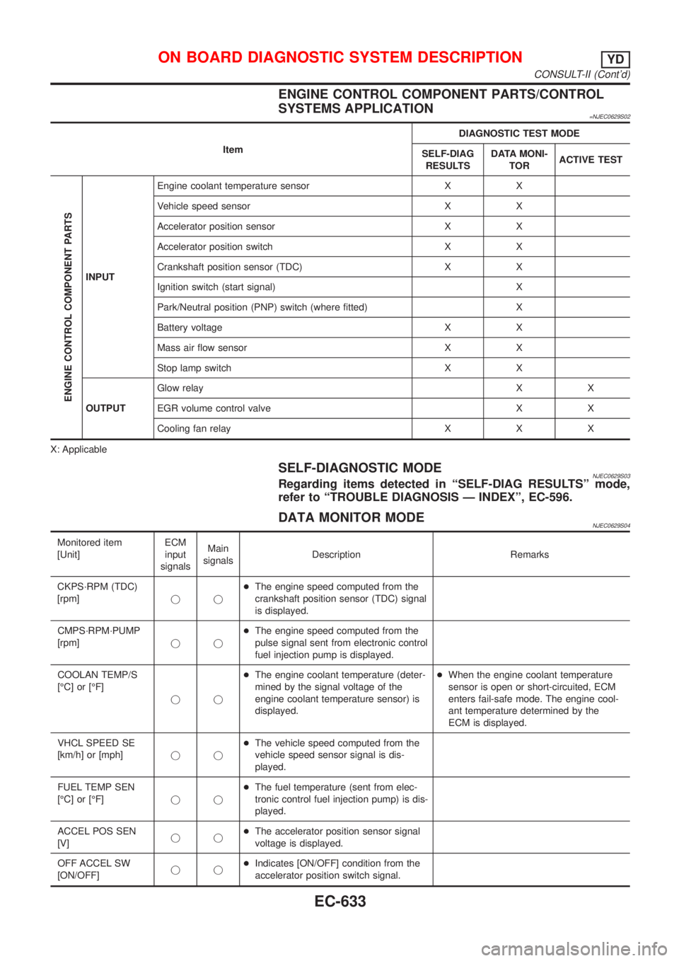
ENGINE CONTROL COMPONENT PARTS/CONTROL
SYSTEMS APPLICATION
=NJEC0629S02
ItemDIAGNOSTIC TEST MODE
SELF-DIAG
RESULTSDATA MONI-
TORACTIVE TEST
ENGINE CONTROL COMPONENT PARTS
INPUTEngine coolant temperature sensor X X
Vehicle speed sensor X X
Accelerator position sensor X X
Accelerator position switch X X
Crankshaft position sensor (TDC) X X
Ignition switch (start signal) X
Park/Neutral position (PNP) switch (where fitted) X
Battery voltage X X
Mass air flow sensor X X
Stop lamp switch X X
OUTPUTGlow relayXX
EGR volume control valve X X
Cooling fan relay X X X
X: Applicable
SELF-DIAGNOSTIC MODENJEC0629S03Regarding items detected in ªSELF-DIAG RESULTSº mode,
refer to ªTROUBLE DIAGNOSIS Ð INDEXº, EC-596.
DATA MONITOR MODENJEC0629S04
Monitored item
[Unit]ECM
input
signalsMain
signalsDescription Remarks
CKPS´RPM (TDC)
[rpm]jj+The engine speed computed from the
crankshaft position sensor (TDC) signal
is displayed.
CMPS´RPM´PUMP
[rpm]jj+The engine speed computed from the
pulse signal sent from electronic control
fuel injection pump is displayed.
COOLAN TEMP/S
[ÉC] or [ÉF]
jj+The engine coolant temperature (deter-
mined by the signal voltage of the
engine coolant temperature sensor) is
displayed.+When the engine coolant temperature
sensor is open or short-circuited, ECM
enters fail-safe mode. The engine cool-
ant temperature determined by the
ECM is displayed.
VHCL SPEED SE
[km/h] or [mph]jj+The vehicle speed computed from the
vehicle speed sensor signal is dis-
played.
FUEL TEMP SEN
[ÉC] or [ÉF]jj+The fuel temperature (sent from elec-
tronic control fuel injection pump) is dis-
played.
ACCEL POS SEN
[V]jj+The accelerator position sensor signal
voltage is displayed.
OFF ACCEL SW
[ON/OFF]jj+Indicates [ON/OFF] condition from the
accelerator position switch signal.
ON BOARD DIAGNOSTIC SYSTEM DESCRIPTIONYD
CONSULT-II (Cont'd)
EC-633
Page 1358 of 2898
![NISSAN ALMERA 2001 Service Manual Monitored item
[Unit]ECM
input
signalsMain
signalsDescription Remarks
SPILL/V [ÉCA]
j+The control position of spill valve (sent
from electronic control fuel injection
pump) is displayed.
BATTERY VOLT NISSAN ALMERA 2001 Service Manual Monitored item
[Unit]ECM
input
signalsMain
signalsDescription Remarks
SPILL/V [ÉCA]
j+The control position of spill valve (sent
from electronic control fuel injection
pump) is displayed.
BATTERY VOLT](/manual-img/5/57348/w960_57348-1357.png)
Monitored item
[Unit]ECM
input
signalsMain
signalsDescription Remarks
SPILL/V [ÉCA]
j+The control position of spill valve (sent
from electronic control fuel injection
pump) is displayed.
BATTERY VOLT [V]
jj+The power supply voltage of ECM is
displayed.
P/N POSI SW*1
[ON/OFF] (where
fitted)jj+Indicates [ON/OFF] condition from the
park/neutral position switch signal.
START SIGNAL
[ON/OFF]jj+Indicates [ON/OFF] condition from the
starter signal.+After starting the engine, [OFF] is dis-
played regardless of the starter signal.
BRAKE SW
[ON/OFF]jj+Indicates [ON/OFF] condition from the
stop lamp switch signal.
BRAKE SW2
[ON/OFF]jj+Indicates [ON/OFF] condition from the
brake pedal position switch signal.
IGN SW
[ON/OFF]jj+Indicates [ON/OFF] condition from igni-
tion switch signal.
MAS AIR/FL SE [V]
jj+The signal voltage of the mass air flow
sensor is displayed.+When the engine is stopped, a certain
value is indicated.
INT/A VOLUME [mg/]+The intake air volume computed from
the mass air flow sensor signal is dis-
played.
F/CUT SIGNAL
[ON/OFF]
j+The [ON/OFF] condition from decelera-
tion fuel cut signal (sent from electronic
control fuel injection pump) is displayed.
OFF´´´Fuel is cut off.
ON´´´Fuel is not cut off.
GLOW RLY
[ON/OFF]j+The glow relay control condition (deter-
mined by ECM according to the input
signal) is displayed.
COOLING FAN
[LOW/HI/OFF]
j+Indicates the control condition of the
cooling fans (determined by ECM
according to the input signal).
+LOW ... Operates at low speed.
HI ... Operates at high speed.
OFF ... Stopped.
BARO SEN [kPa]
jj+The barometric pressure (determined
by the signal voltage from the baromet-
ric pressure sensor built into the ECM)
is displayed.
EGR VOL CON/V
[step]
j+Indicates the EGR volume control value
computed by the ECM according to the
input signals.
+The opening becomes larger as the
value increases.
*1: On models not equipped with park/neutral position (PNP) switch, ªOFFº is always displayed regardless of gear shift position.
NOTE:
Any monitored item that does not match the vehicle being diagnosed is deleted from the display automatically.
ON BOARD DIAGNOSTIC SYSTEM DESCRIPTIONYD
CONSULT-II (Cont'd)
EC-634
Page 1376 of 2898
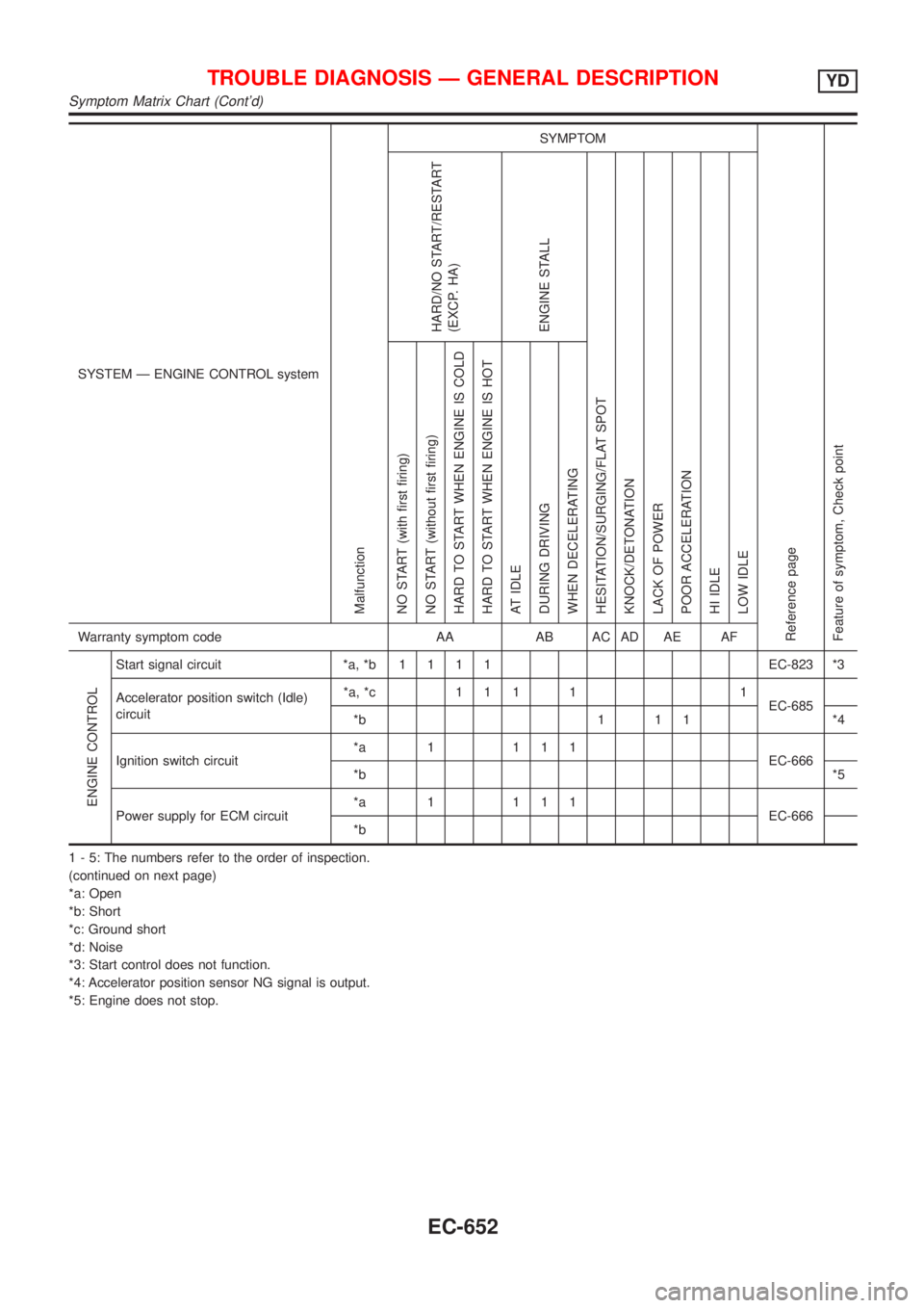
SYSTEM Ð ENGINE CONTROL system
Malfunction
SYMPTOM
Reference page
Feature of symptom, Check pointHARD/NO START/RESTART
(EXCP. HA)
ENGINE STALL
HESITATION/SURGING/FLAT SPOT
KNOCK/DETONATION
LACK OF POWER
POOR ACCELERATION
HI IDLE
LOW IDLE NO START (with first firing)
NO START (without first firing)
HARD TO START WHEN ENGINE IS COLD
HARD TO START WHEN ENGINE IS HOT
AT IDLE
DURING DRIVING
WHEN DECELERATINGWarranty symptom code AA AB AC AD AE AF
ENGINE CONTROL
Start signal circuit *a, *b1111EC-823 *3
Accelerator position switch (Idle)
circuit*a, *c 1 1 1 1 1
EC-685
*b 1 1 1 *4
Ignition switch circuit*a 1 111
EC-666
*b*5
Power supply for ECM circuit*a 1 111
EC-666
*b
1 - 5: The numbers refer to the order of inspection.
(continued on next page)
*a: Open
*b: Short
*c: Ground short
*d: Noise
*3: Start control does not function.
*4: Accelerator position sensor NG signal is output.
*5: Engine does not stop.
TROUBLE DIAGNOSIS Ð GENERAL DESCRIPTIONYD
Symptom Matrix Chart (Cont'd)
EC-652
Page 1377 of 2898
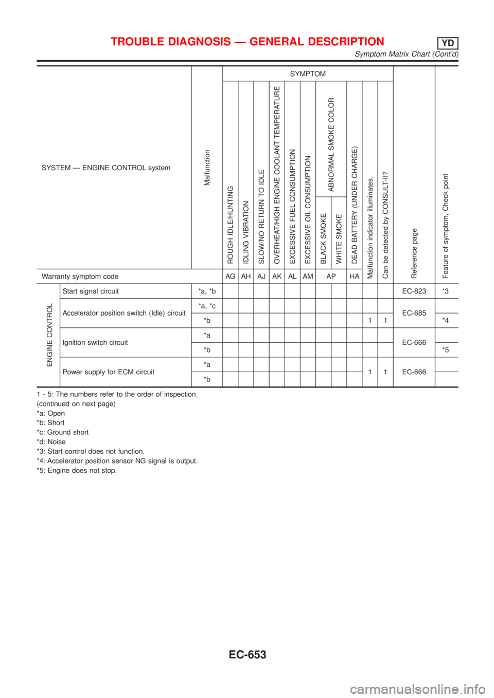
SYSTEM Ð ENGINE CONTROL system
Malfunction
SYMPTOM
Reference page
Feature of symptom, Check pointROUGH IDLE/HUNTING
IDLING VIBRATION
SLOW/NO RETURN TO IDLE
OVERHEAT/HIGH ENGINE COOLANT TEMPERATURE
EXCESSIVE FUEL CONSUMPTION
EXCESSIVE OIL CONSUMPTION
ABNORMAL SMOKE COLOR
DEAD BATTERY (UNDER CHARGE)
Malfunction indicator illuminates.
Can be detected by CONSULT-II?BLACK SMOKE
WHITE SMOKEWarranty symptom code AG AH AJ AK AL AM AP HA
ENGINE CONTROL
Start signal circuit *a, *b EC-823 *3
Accelerator position switch (Idle) circuit*a, *c
EC-685
*b 1 1 *4
Ignition switch circuit*a
EC-666
*b*5
Power supply for ECM circuit*a
1 1 EC-666
*b
1 - 5: The numbers refer to the order of inspection.
(continued on next page)
*a: Open
*b: Short
*c: Ground short
*d: Noise
*3: Start control does not function.
*4: Accelerator position sensor NG signal is output.
*5: Engine does not stop.
TROUBLE DIAGNOSIS Ð GENERAL DESCRIPTIONYD
Symptom Matrix Chart (Cont'd)
EC-653
Page 1378 of 2898
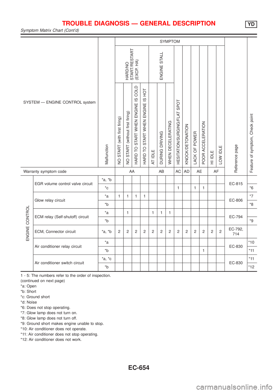
SYSTEM Ð ENGINE CONTROL system
Malfunction
SYMPTOM
Reference page
Feature of symptom, Check pointHARD/NO
START/RESTART
(EXCP. HA)
ENGINE STALL
HESITATION/SURGING/FLAT SPOT
KNOCK/DETONATION
LACK OF POWER
POOR ACCELERATION
HI IDLE
LOW IDLE NO START (with first firing)
NO START (without first firing)
HARD TO START WHEN ENGINE IS COLD
HARD TO START WHEN ENGINE IS HOT
AT IDLE
DURING DRIVING
WHEN DECELERATINGWarranty symptom code AA AB AC AD AE AF
ENGINE CONTROL
EGR volume control valve circuit*a, *b
EC-815
*c 1 1 1 *6
Glow relay circuit*a 1111
EC-806*7
*b*8
ECM relay (Self-shutoff) circuit*a 1 111
EC-794
*b*9
ECM, Connector circuit *a, *b2222222222222EC-792,
714
Air conditioner relay circuit*a
EC-830*10
*b 1 *11
Air conditioner switch circuit*a, *c
EC-830*11
*b*12
1 - 5: The numbers refer to the order of inspection.
(continued on next page)
*a: Open
*b: Short
*c: Ground short
*d: Noise
*6: Does not stop operating.
*7: Glow lamp does not turn on.
*8: Glow lamp does not turn off.
*9: Ground short makes engine unable to stop.
*10: Air conditioner does not operate.
*11: Air conditioner does not stop operating.
*12: Air conditioner does not work.
TROUBLE DIAGNOSIS Ð GENERAL DESCRIPTIONYD
Symptom Matrix Chart (Cont'd)
EC-654
Page 1380 of 2898
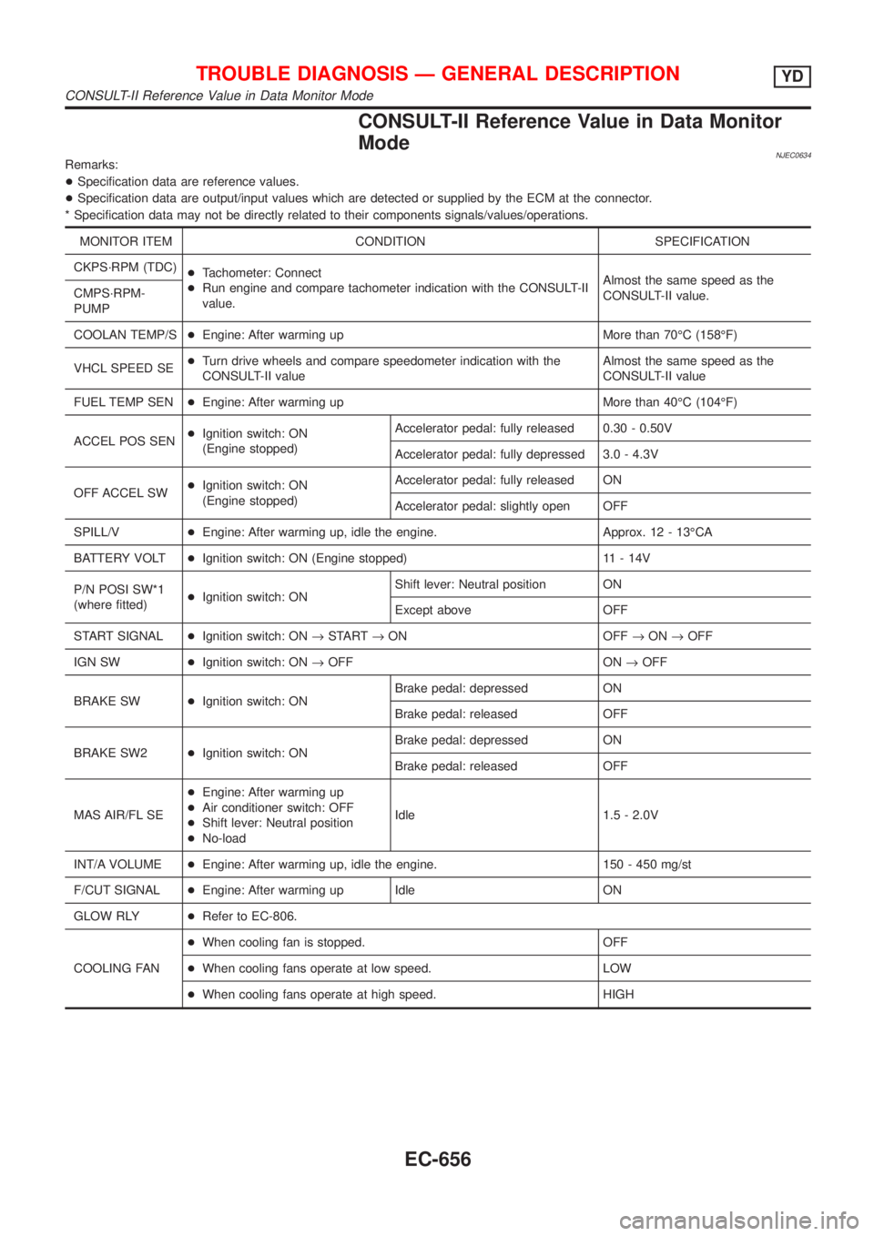
CONSULT-II Reference Value in Data Monitor
Mode
NJEC0634Remarks:
+Specification data are reference values.
+Specification data are output/input values which are detected or supplied by the ECM at the connector.
* Specification data may not be directly related to their components signals/values/operations.
MONITOR ITEM CONDITION SPECIFICATION
CKPS´RPM (TDC)
+Tachometer: Connect
+Run engine and compare tachometer indication with the CONSULT-II
value.Almost the same speed as the
CONSULT-II value. CMPS´RPM-
PUMP
COOLAN TEMP/S+Engine: After warming up More than 70ÉC (158ÉF)
VHCL SPEED SE+Turn drive wheels and compare speedometer indication with the
CONSULT-II valueAlmost the same speed as the
CONSULT-II value
FUEL TEMP SEN+Engine: After warming up More than 40ÉC (104ÉF)
ACCEL POS SEN+Ignition switch: ON
(Engine stopped)Accelerator pedal: fully released 0.30 - 0.50V
Accelerator pedal: fully depressed 3.0 - 4.3V
OFF ACCEL SW+Ignition switch: ON
(Engine stopped)Accelerator pedal: fully released ON
Accelerator pedal: slightly open OFF
SPILL/V+Engine: After warming up, idle the engine. Approx. 12 - 13ÉCA
BATTERY VOLT+Ignition switch: ON (Engine stopped) 11 - 14V
P/N POSI SW*1
(where fitted)+Ignition switch: ONShift lever: Neutral position ON
Except above OFF
START SIGNAL+Ignition switch: ON®START®ON OFF®ON®OFF
IGN SW+Ignition switch: ON®OFF ON®OFF
BRAKE SW+Ignition switch: ONBrake pedal: depressed ON
Brake pedal: released OFF
BRAKE SW2+Ignition switch: ONBrake pedal: depressed ON
Brake pedal: released OFF
MAS AIR/FL SE+Engine: After warming up
+Air conditioner switch: OFF
+Shift lever: Neutral position
+No-loadIdle 1.5 - 2.0V
INT/A VOLUME+Engine: After warming up, idle the engine. 150 - 450 mg/st
F/CUT SIGNAL+Engine: After warming up Idle ON
GLOW RLY+Refer to EC-806.
COOLING FAN+When cooling fan is stopped. OFF
+When cooling fans operate at low speed. LOW
+When cooling fans operate at high speed. HIGH
TROUBLE DIAGNOSIS Ð GENERAL DESCRIPTIONYD
CONSULT-II Reference Value in Data Monitor Mode
EC-656
Page 1539 of 2898
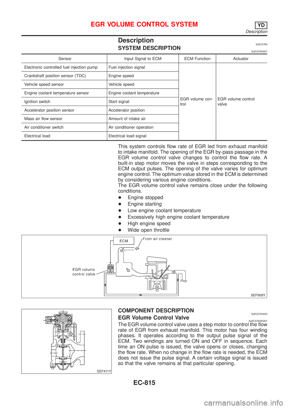
DescriptionNJEC0764SYSTEM DESCRIPTIONNJEC0764S01
Sensor Input Signal to ECM ECM Function Actuator
Electronic controlled fuel injection pump Fuel injection signal
EGR volume con-
trolEGR volume control
valve Crankshaft position sensor (TDC) Engine speed
Vehicle speed sensor Vehicle speed
Engine coolant temperature sensor Engine coolant temperature
Ignition switch Start signal
Accelerator position sensor Accelerator position
Mass air flow sensor Amount of intake air
Air conditioner switch Air conditioner operation
Electrical load Electrical load signal
This system controls flow rate of EGR led from exhaust manifold
to intake manifold. The opening of the EGR by-pass passage in the
EGR volume control valve changes to control the flow rate. A
built-in step motor moves the valve in steps corresponding to the
ECM output pulses. The opening of the valve varies for optimum
engine control. The optimum value stored in the ECM is determined
by considering various engine conditions.
The EGR volume control valve remains close under the following
conditions.
+Engine stopped
+Engine starting
+Low engine coolant temperature
+Excessively high engine coolant temperature
+High engine speed
+Wide open throttle
SEF908Y
SEF411Y
COMPONENT DESCRIPTIONNJEC0764S02EGR Volume Control ValveNJEC0764S0201The EGR volume control valve uses a step motor to control the flow
rate of EGR from exhaust manifold. This motor has four winding
phases. It operates according to the output pulse signal of the
ECM. Two windings are turned ON and OFF in sequence. Each
time an ON pulse is issued, the valve opens or closes, changing
the flow rate. When no change in the flow rate is needed, the ECM
does not issue the pulse signal. A certain voltage signal is issued
so that the valve remains at that particular opening.
EGR VOLUME CONTROL SYSTEMYD
Description
EC-815
Page 1634 of 2898
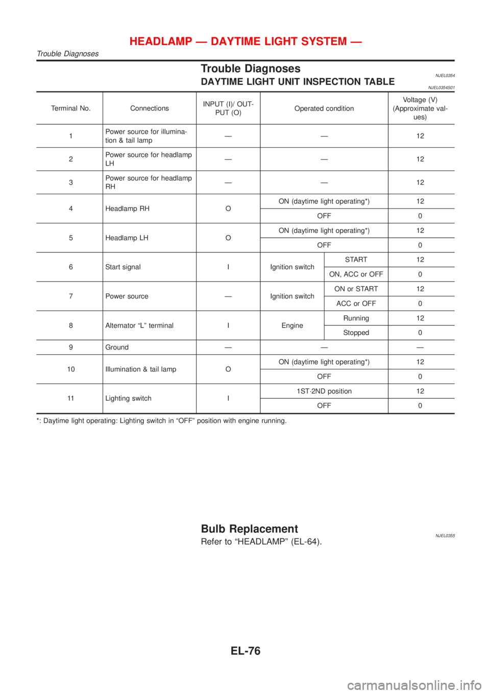
Trouble DiagnosesNJEL0354DAYTIME LIGHT UNIT INSPECTION TABLENJEL0354S01
Terminal No. ConnectionsINPUT (I)/ OUT-
PUT (O)Operated conditionVoltage (V)
(Approximate val-
ues)
1Power source for illumina-
tion & tail lampÐÐ12
2Power source for headlamp
LHÐÐ12
3Power source for headlamp
RHÐÐ12
4 Headlamp RH OON (daytime light operating*) 12
OFF 0
5 Headlamp LH OON (daytime light operating*) 12
OFF 0
6 Start signal I Ignition switchSTART 12
ON, ACC or OFF 0
7 Power source Ð Ignition switchON or START 12
ACC or OFF 0
8 Alternator ªLº terminal I EngineRunning 12
Stopped 0
9 Ground Ð Ð Ð
10 Illumination & tail lamp OON (daytime light operating*) 12
OFF 0
11 Lighting switch I1ST´2ND position 12
OFF 0
*: Daytime light operating: Lighting switch in ªOFFº position with engine running.
Bulb ReplacementNJEL0355Refer to ªHEADLAMPº (EL-64).
HEADLAMP Ð DAYTIME LIGHT SYSTEM Ð
Trouble Diagnoses
EL-76