2001 NISSAN ALMERA parking brake
[x] Cancel search: parking brakePage 17 of 2898

SMA827CA
Checking A/T FluidNJAT02281. Warm up engine.
2. Check for fluid leakage.
3. Before driving, fluid level can be checked at fluid temperatures
of 30 to 50ÉC (86 to 122ÉF) using ªCOLDº range on dipstick.
a. Park vehicle on level surface and set parking brake.
b. Start engine and move selector lever through each gear posi-
tion. Leave selector lever in ªPº position.
c. Check fluid level with engine idling.
d. Remove dipstick and note reading. If level is at low side of
either range, and fluid to the charging pipe.
e. Re-insert dipstick into charging pipe as far as it will go.
f. Remove dipstick and note reading. If reading is at low side of
range, add fluid to the charging pipe.
Do not overfill.
4. Drive vehicle for approximately 5 minutes in urban areas.
5. Re-check fluid level at fluid temperatures of 50 to 80ÉC (122
to 176ÉF) using ªHOTº range on dipstick.
SMA853B
6. Check fluid condition.
+If fluid is very dark or smells burned, refer to AT section for
checking operation of A/T. Flush cooling system after repair of
A/T.
+If A/T fluid contains frictional material (clutches, bands, etc.),
replace radiator and flush cooler line using cleaning solvent
and compressed air after repair of A/T. Refer to LC-16, ªRadia-
torº.
SMA027D
Changing A/T FluidNJAT02291. Warm up A/T fluid.
2. Stop engine.
3. Drain A/T fluid from drain plug and refill with new A/T fluid.
Always refill same volume with drained fluid.
Fluid grade:
Nissan Matic ªDº or Genuine Nissan Automatic
Transmission Fluid. Refer to ªRECOMMENDED FLU-
IDS AND LUBRICANTSº, MA-16.
Fluid capacity (With torque converter):
7.0!(6-1/8 Imp qt)
Drain plug:
: 29 - 39 N´m (3.0 - 4.0 kg-m, 22 - 29 ft-lb)
4. Run engine at idle speed for five minutes.
5. Check fluid level and condition. Refer to ªChecking A/T Fluidº.
If fluid is still dirty, repeat steps 2 through 5.
A/T FLUID
Checking A/T Fluid
AT-15
Page 24 of 2898

Shift MechanismNJAT0013CONSTRUCTIONNJAT0013S01
SAT998I
1. Torque converter
2. Oil pump
3. Input shaft
4. Brake band
5. Reverse clutch
6. High clutch
7. Front sun gear
8. Front pinion gear9. Front internal gear
10. Front planetary carrier
11. Rear sun gear
12. Rear pinion gear
13. Rear internal gear
14. Rear planetary carrier
15. Forward clutch
16. Forward one-way clutch17. Overrun clutch
18. Low one-way clutch
19. Low & reverse brake
20. Parking pawl
21. Parking gear
22. Output shaft
23. Idle gear
24. Output gear
FUNCTION OF CLUTCH AND BRAKENJAT0013S03
Clutch and brake components Abbr. Function
5Reverse clutch R/C To transmit input power to front sun gear7.
6High clutch H/C To transmit input power to front planetary carrier10.
15Forward clutch F/C To connect front planetary carrier10with forward one-way clutch16.
17Overrun clutch O/C To connect front planetary carrier10with rear internal gear13.
4Brake band B/B To lock front sun gear7.
16Forward one-way clutch F/O.C When forward clutch15is engaged, to stop rear internal gear13from rotat-
ing in opposite direction against engine revolution.
18Low one-way clutch L/O.C To stop front planetary carrier10from rotating in opposite direction against
engine revolution.
19Low & reverse brake L & R/B To lock front planetary carrier10.
OVERALL SYSTEM
Shift Mechanism
AT-22
Page 83 of 2898
SAT513G
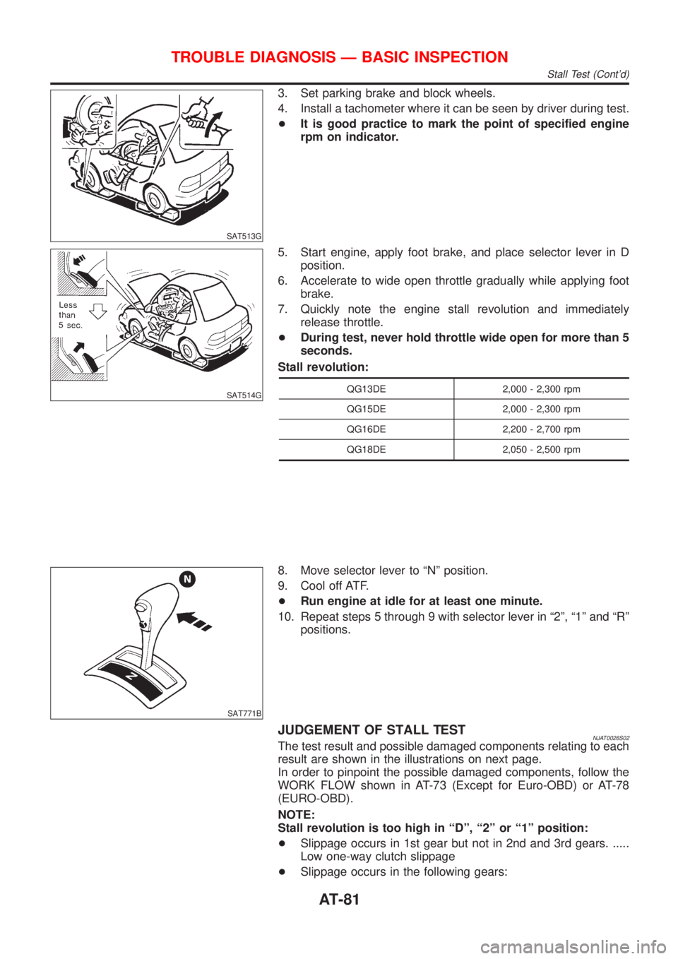
3. Set parking brake and block wheels.
4. Install a tachometer where it can be seen by driver during test.
+It is good practice to mark the point of specified engine
rpm on indicator.
SAT514G
5. Start engine, apply foot brake, and place selector lever in D
position.
6. Accelerate to wide open throttle gradually while applying foot
brake.
7. Quickly note the engine stall revolution and immediately
release throttle.
+During test, never hold throttle wide open for more than 5
seconds.
Stall revolution:
QG13DE 2,000 - 2,300 rpm
QG15DE 2,000 - 2,300 rpm
QG16DE 2,200 - 2,700 rpm
QG18DE 2,050 - 2,500 rpm
SAT771B
8. Move selector lever to ªNº position.
9. Cool off ATF.
+Run engine at idle for at least one minute.
10. Repeat steps 5 through 9 with selector lever in ª2º, ª1º and ªRº
positions.
JUDGEMENT OF STALL TESTNJAT0026S02The test result and possible damaged components relating to each
result are shown in the illustrations on next page.
In order to pinpoint the possible damaged components, follow the
WORK FLOW shown in AT-73 (Except for Euro-OBD) or AT-78
(EURO-OBD).
NOTE:
Stall revolution is too high in ªDº, ª2º or ª1º position:
+Slippage occurs in 1st gear but not in 2nd and 3rd gears. .....
Low one-way clutch slippage
+Slippage occurs in the following gears:
TROUBLE DIAGNOSIS Ð BASIC INSPECTION
Stall Test (Cont'd)
AT-81
Page 86 of 2898
SAT561J
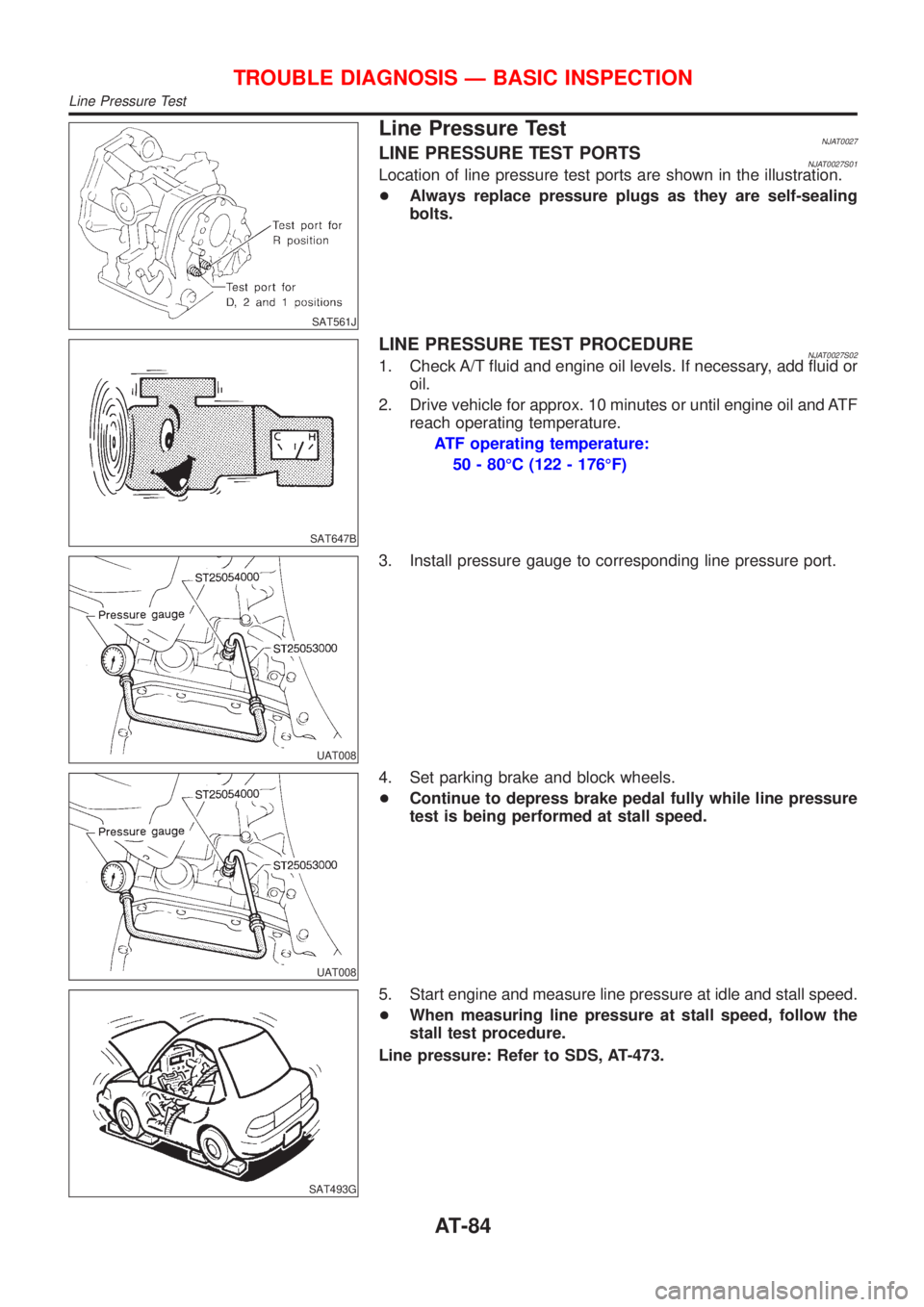
Line Pressure TestNJAT0027LINE PRESSURE TEST PORTSNJAT0027S01Location of line pressure test ports are shown in the illustration.
+Always replace pressure plugs as they are self-sealing
bolts.
SAT647B
LINE PRESSURE TEST PROCEDURENJAT0027S021. Check A/T fluid and engine oil levels. If necessary, add fluid or
oil.
2. Drive vehicle for approx. 10 minutes or until engine oil and ATF
reach operating temperature.
ATF operating temperature:
50 - 80ÉC (122 - 176ÉF)
UAT008
3. Install pressure gauge to corresponding line pressure port.
UAT008
4. Set parking brake and block wheels.
+Continue to depress brake pedal fully while line pressure
test is being performed at stall speed.
SAT493G
5. Start engine and measure line pressure at idle and stall speed.
+When measuring line pressure at stall speed, follow the
stall test procedure.
Line pressure: Refer to SDS, AT-473.
TROUBLE DIAGNOSIS Ð BASIC INSPECTION
Line Pressure Test
AT-84
Page 92 of 2898
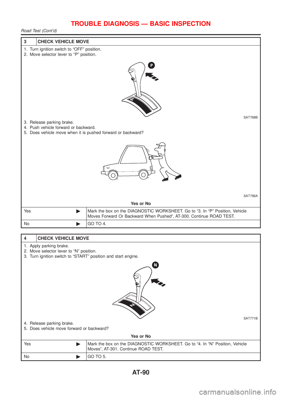
3 CHECK VEHICLE MOVE
1. Turn ignition switch to ªOFFº position.
2. Move selector lever to ªPº position.
SAT768B
3. Release parking brake.
4. Push vehicle forward or backward.
5. Does vehicle move when it is pushed forward or backward?
SAT796A
YesorNo
Ye s©Mark the box on the DIAGNOSTIC WORKSHEET. Go to ª3. In ªPº Position, Vehicle
Moves Forward Or Backward When Pushedº, AT-300. Continue ROAD TEST.
No©GO TO 4.
4 CHECK VEHICLE MOVE
1. Apply parking brake.
2. Move selector lever to ªNº position.
3. Turn ignition switch to ªSTARTº position and start engine.
SAT771B
4. Release parking brake.
5. Does vehicle move forward or backward?
YesorNo
Ye s©Mark the box on the DIAGNOSTIC WORKSHEET. Go to ª4. In ªNº Position, Vehicle
Movesº, AT-301. Continue ROAD TEST.
No©GO TO 5.
TROUBLE DIAGNOSIS Ð BASIC INSPECTION
Road Test (Cont'd)
AT-90
Page 107 of 2898

Symptom ChartNJAT0029Numbers are arranged in order of inspection.
Perform inspections starting with number one and work up.
Symptom Condition Diagnostic ItemReference Page
General and
except for
Euro-OBDEURO-OBD
Engine cannot start in ªPº and ªNº
positions.
AT-299ON vehicle1. Ignition switch and starterEL-10, ªPOWER SUPPLY
ROUTINGº and SC-13,
ªSTARTING SYSTEMº
2. Control cable adjustment AT-352¬
3. PNP switch adjustment AT-352¬
Engine starts in position other than
ªNº and ªPº positions.
AT-299ON vehicle1. Control cable adjustment AT-352¬
2. PNP switch adjustment AT-352¬
Transaxle noise in ªPº and ªNº
positions.ON vehicle1. Fluid level AT-80¬
2. Line pressure test AT-84¬
3. Throttle position sensor (Adjustment)EC-207,
ªDTC P0120
THROTTLE
POSITION
SENSORºEC-207,
ªDTC P0120
THROTTLE
POSITION
SENSORº
4. Vehicle speed sensor´A/T (Revolution
sensor) and vehicle speed sensor´MTRAT-126,
AT-131AT-195,
AT-281
5. Engine speed signal AT-172 AT-200
OFF vehicle6. Oil pump AT-384¬
7. Torque converter AT-366¬
Vehicle moves when changing into
ªPº position, or parking gear does
not disengage when shifted out of
ªPº position.
AT-300ON vehicle 1. Control cable adjustment AT-352¬
OFF vehicle 2. Parking componentsAT-361,
AT-362AT-362
Vehicle runs in ªNº position.
AT-301ON vehicle 1. Control cable adjustment AT-352¬
OFF vehicle2. Forward clutch AT-412¬
3. Reverse clutch AT-403¬
4. Overrun clutch AT-412¬
Vehicle will not run in ªRº position
(but runs in ªDº, ª2º and ª1º posi-
tions). Clutch slips.
Very poor acceleration.
AT-305ON vehicle1. Control cable adjustment AT-352¬
2. Line pressure test AT-84¬
3. Line pressure solenoid valve AT-176 AT-239
4. Control valve assembly AT-351¬
OFF vehicle5. Reverse clutch AT-403¬
6. High clutch AT-407¬
7. Forward clutch AT-412¬
8. Overrun clutch AT-412¬
9. Low & reverse brake AT-419¬
TROUBLE DIAGNOSIS Ð GENERAL DESCRIPTION
Symptom Chart
AT-105
Page 116 of 2898
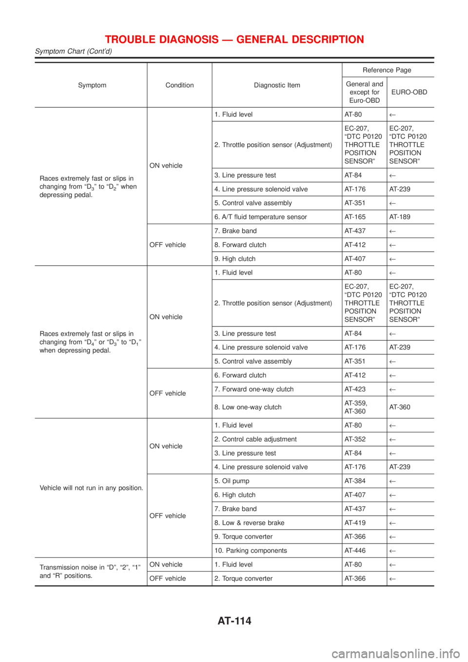
Symptom Condition Diagnostic ItemReference Page
General and
except for
Euro-OBDEURO-OBD
Races extremely fast or slips in
changing from ªD
3ºtoªD2º when
depressing pedal.ON vehicle1. Fluid level AT-80¬
2. Throttle position sensor (Adjustment)EC-207,
ªDTC P0120
THROTTLE
POSITION
SENSORºEC-207,
ªDTC P0120
THROTTLE
POSITION
SENSORº
3. Line pressure test AT-84¬
4. Line pressure solenoid valve AT-176 AT-239
5. Control valve assembly AT-351¬
6. A/T fluid temperature sensor AT-165 AT-189
OFF vehicle7. Brake band AT-437¬
8. Forward clutch AT-412¬
9. High clutch AT-407¬
Races extremely fast or slips in
changing from ªD
4ºorªD3ºtoªD1º
when depressing pedal.ON vehicle1. Fluid level AT-80¬
2. Throttle position sensor (Adjustment)EC-207,
ªDTC P0120
THROTTLE
POSITION
SENSORºEC-207,
ªDTC P0120
THROTTLE
POSITION
SENSORº
3. Line pressure test AT-84¬
4. Line pressure solenoid valve AT-176 AT-239
5. Control valve assembly AT-351¬
OFF vehicle6. Forward clutch AT-412¬
7. Forward one-way clutch AT-423¬
8. Low one-way clutchAT-359,
AT-360AT-360
Vehicle will not run in any position.ON vehicle1. Fluid level AT-80¬
2. Control cable adjustment AT-352¬
3. Line pressure test AT-84¬
4. Line pressure solenoid valve AT-176 AT-239
OFF vehicle5. Oil pump AT-384¬
6. High clutch AT-407¬
7. Brake band AT-437¬
8. Low & reverse brake AT-419¬
9. Torque converter AT-366¬
10. Parking components AT-446¬
Transmission noise in ªDº, ª2º, ª1º
and ªRº positions.ON vehicle 1. Fluid level AT-80¬
OFF vehicle 2. Torque converter AT-366¬
TROUBLE DIAGNOSIS Ð GENERAL DESCRIPTION
Symptom Chart (Cont'd)
AT-114
Page 345 of 2898
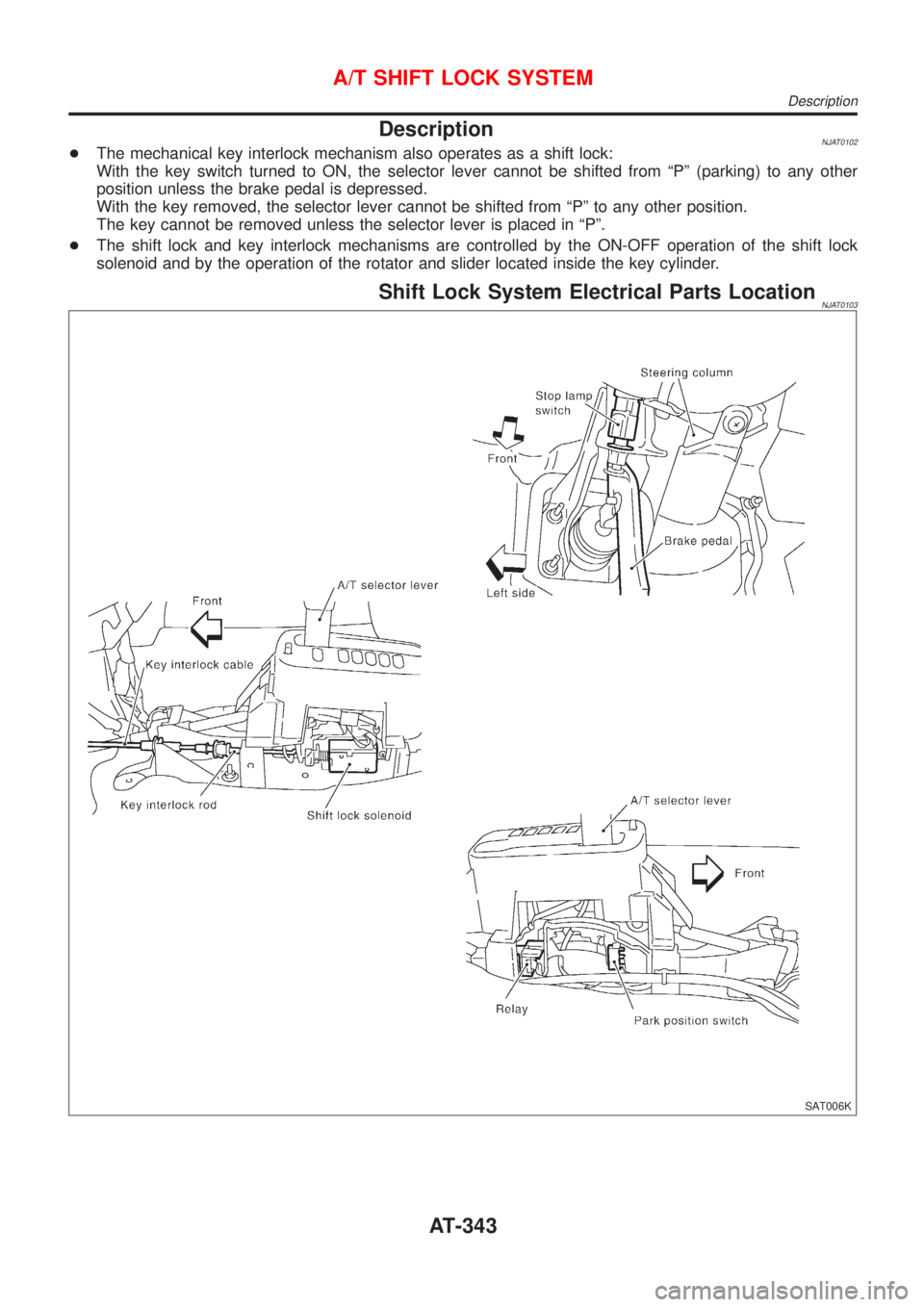
DescriptionNJAT0102+The mechanical key interlock mechanism also operates as a shift lock:
With the key switch turned to ON, the selector lever cannot be shifted from ªPº (parking) to any other
position unless the brake pedal is depressed.
With the key removed, the selector lever cannot be shifted from ªPº to any other position.
The key cannot be removed unless the selector lever is placed in ªPº.
+The shift lock and key interlock mechanisms are controlled by the ON-OFF operation of the shift lock
solenoid and by the operation of the rotator and slider located inside the key cylinder.
Shift Lock System Electrical Parts LocationNJAT0103
SAT006K
A/T SHIFT LOCK SYSTEM
Description
AT-343