2001 NISSAN ALMERA spark plugs replace
[x] Cancel search: spark plugs replacePage 820 of 2898

MEF036D
SEF233G
SEF234G
IntroductionNJEC0036The engine has an ECM to control major systems such as fuel
control, ignition control, idle air control system, etc. The ECM
accepts input signals from sensors and instantly drives actuators.
It is essential that both input and output signals are proper and
stable. At the same time, it is important that there are no problems
such as vacuum leaks, fouled spark plugs, or other problems with
the engine.
It is much more difficult to diagnose a problem that occurs intermit-
tently rather than continuously. Most intermittent problems are
caused by poor electric connections or improper wiring. In this
case, careful checking of suspected circuits may help prevent the
replacement of good parts.
A visual check only may not find the cause of the problems. A road
test with CONSULT-II (or GST) or a circuit tester connected should
be performed. Follow the ªWork Flowº on EC-98.
Before undertaking actual checks, take a few minutes to talk with
a customer who approaches with a driveability complaint. The cus-
tomer can supply good information about such problems, espe-
cially intermittent ones. Find out what symptoms are present and
under what conditions they occur. A ªDiagnostic Worksheetº like the
example on next page should be used.
Start your diagnosis by looking for ªconventionalº problems first.
This will help troubleshoot driveability problems on an electronically
controlled engine vehicle.
SEF907L
DIAGNOSTIC WORKSHEETNJEC0036S01There are many operating conditions that lead to the malfunction
of engine components. A good grasp of such conditions can make
trouble-shooting faster and more accurate.
In general, each customer feels differently about a problem. It is
important to fully understand the symptoms or conditions for a
customer complaint.
Utilize a diagnostic worksheet like the one on the next page in order
to organize all the information for troubleshooting.
Some conditions may cause the malfunction indicator lamp to
come on steady or blink and DTC to be detected.
Example:
Vehicle ran out of fuel, which caused the engine to misfire.
TROUBLE DIAGNOSIS Ð INTRODUCTIONQG
EC-96
Page 1045 of 2898
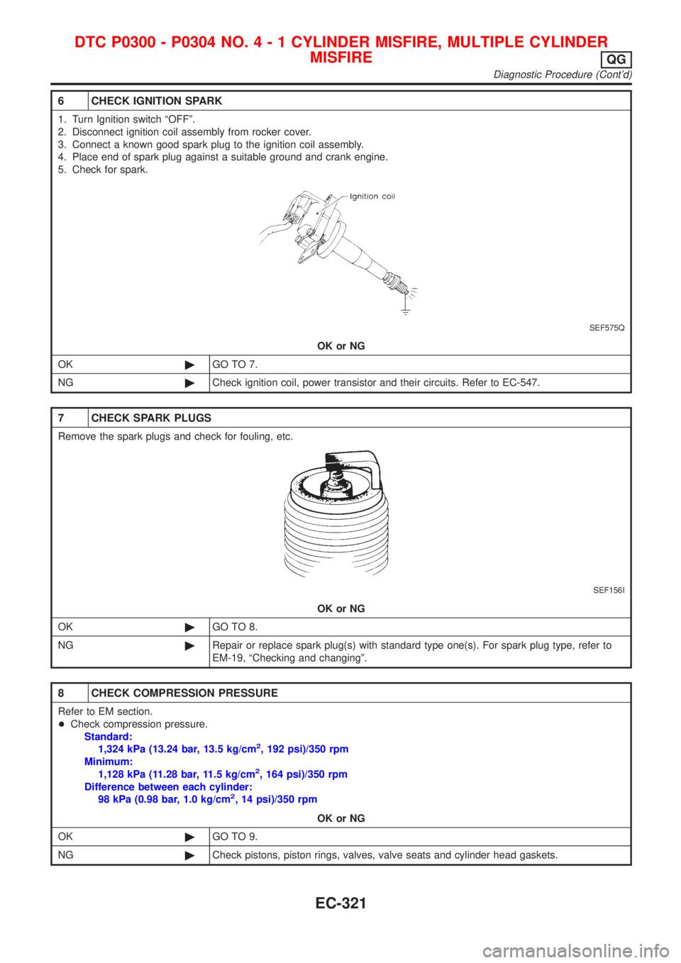
6 CHECK IGNITION SPARK
1. Turn Ignition switch ªOFFº.
2. Disconnect ignition coil assembly from rocker cover.
3. Connect a known good spark plug to the ignition coil assembly.
4. Place end of spark plug against a suitable ground and crank engine.
5. Check for spark.
SEF575Q
OK or NG
OK©GO TO 7.
NG©Check ignition coil, power transistor and their circuits. Refer to EC-547.
7 CHECK SPARK PLUGS
Remove the spark plugs and check for fouling, etc.
SEF156I
OK or NG
OK©GO TO 8.
NG©Repair or replace spark plug(s) with standard type one(s). For spark plug type, refer to
EM-19, ªChecking and changingº.
8 CHECK COMPRESSION PRESSURE
Refer to EM section.
+Check compression pressure.
Standard:
1,324 kPa (13.24 bar, 13.5 kg/cm
2, 192 psi)/350 rpm
Minimum:
1,128 kPa (11.28 bar, 11.5 kg/cm
2, 164 psi)/350 rpm
Difference between each cylinder:
98 kPa (0.98 bar, 1.0 kg/cm
2, 14 psi)/350 rpm
OK or NG
OK©GO TO 9.
NG©Check pistons, piston rings, valves, valve seats and cylinder head gaskets.
DTC P0300 - P0304 NO.4-1CYLINDER MISFIRE, MULTIPLE CYLINDER
MISFIRE
QG
Diagnostic Procedure (Cont'd)
EC-321
Page 2149 of 2898
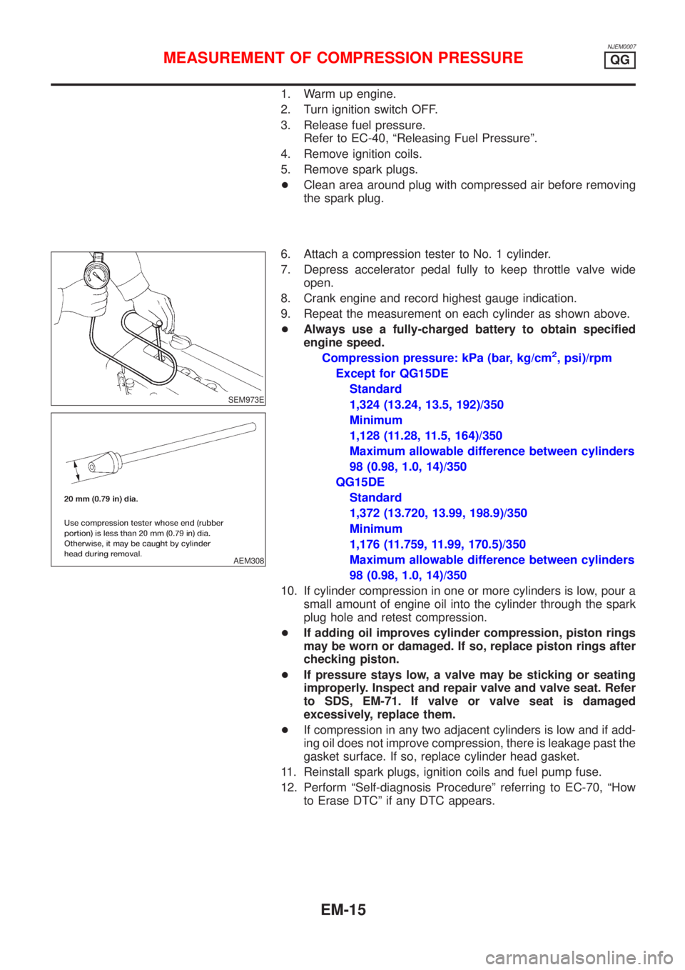
NJEM0007
1. Warm up engine.
2. Turn ignition switch OFF.
3. Release fuel pressure.
Refer to EC-40, ªReleasing Fuel Pressureº.
4. Remove ignition coils.
5. Remove spark plugs.
+Clean area around plug with compressed air before removing
the spark plug.
SEM973E
AEM308
6. Attach a compression tester to No. 1 cylinder.
7. Depress accelerator pedal fully to keep throttle valve wide
open.
8. Crank engine and record highest gauge indication.
9. Repeat the measurement on each cylinder as shown above.
+Always use a fully-charged battery to obtain specified
engine speed.
Compression pressure: kPa (bar, kg/cm
2, psi)/rpm
Except for QG15DE
Standard
1,324 (13.24, 13.5, 192)/350
Minimum
1,128 (11.28, 11.5, 164)/350
Maximum allowable difference between cylinders
98 (0.98, 1.0, 14)/350
QG15DE
Standard
1,372 (13.720, 13.99, 198.9)/350
Minimum
1,176 (11.759, 11.99, 170.5)/350
Maximum allowable difference between cylinders
98 (0.98, 1.0, 14)/350
10. If cylinder compression in one or more cylinders is low, pour a
small amount of engine oil into the cylinder through the spark
plug hole and retest compression.
+If adding oil improves cylinder compression, piston rings
may be worn or damaged. If so, replace piston rings after
checking piston.
+If pressure stays low, a valve may be sticking or seating
improperly. Inspect and repair valve and valve seat. Refer
to SDS, EM-71. If valve or valve seat is damaged
excessively, replace them.
+If compression in any two adjacent cylinders is low and if add-
ing oil does not improve compression, there is leakage past the
gasket surface. If so, replace cylinder head gasket.
11. Reinstall spark plugs, ignition coils and fuel pump fuse.
12. Perform ªSelf-diagnosis Procedureº referring to EC-70, ªHow
to Erase DTCº if any DTC appears.
MEASUREMENT OF COMPRESSION PRESSUREQG
EM-15
Page 2153 of 2898
SEM870F
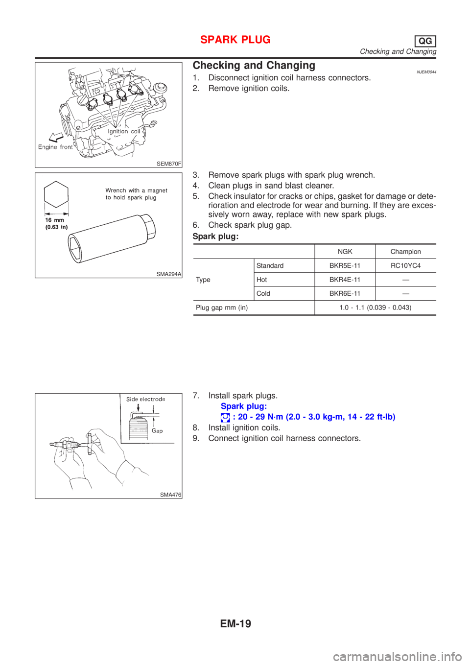
Checking and ChangingNJEM00441. Disconnect ignition coil harness connectors.
2. Remove ignition coils.
SMA294A
3. Remove spark plugs with spark plug wrench.
4. Clean plugs in sand blast cleaner.
5. Check insulator for cracks or chips, gasket for damage or dete-
rioration and electrode for wear and burning. If they are exces-
sively worn away, replace with new spark plugs.
6. Check spark plug gap.
Spark plug:
NGK Champion
TypeStandard BKR5E-11 RC10YC4
Hot BKR4E-11 Ð
Cold BKR6E-11 Ð
Plug gap mm (in) 1.0 - 1.1 (0.039 - 0.043)
SMA476
7. Install spark plugs.
Spark plug:
: 20 - 29 N´m (2.0 - 3.0 kg-m, 14 - 22 ft-lb)
8. Install ignition coils.
9. Connect ignition coil harness connectors.
SPARK PLUGQG
Checking and Changing
EM-19
Page 2178 of 2898
SEM921F
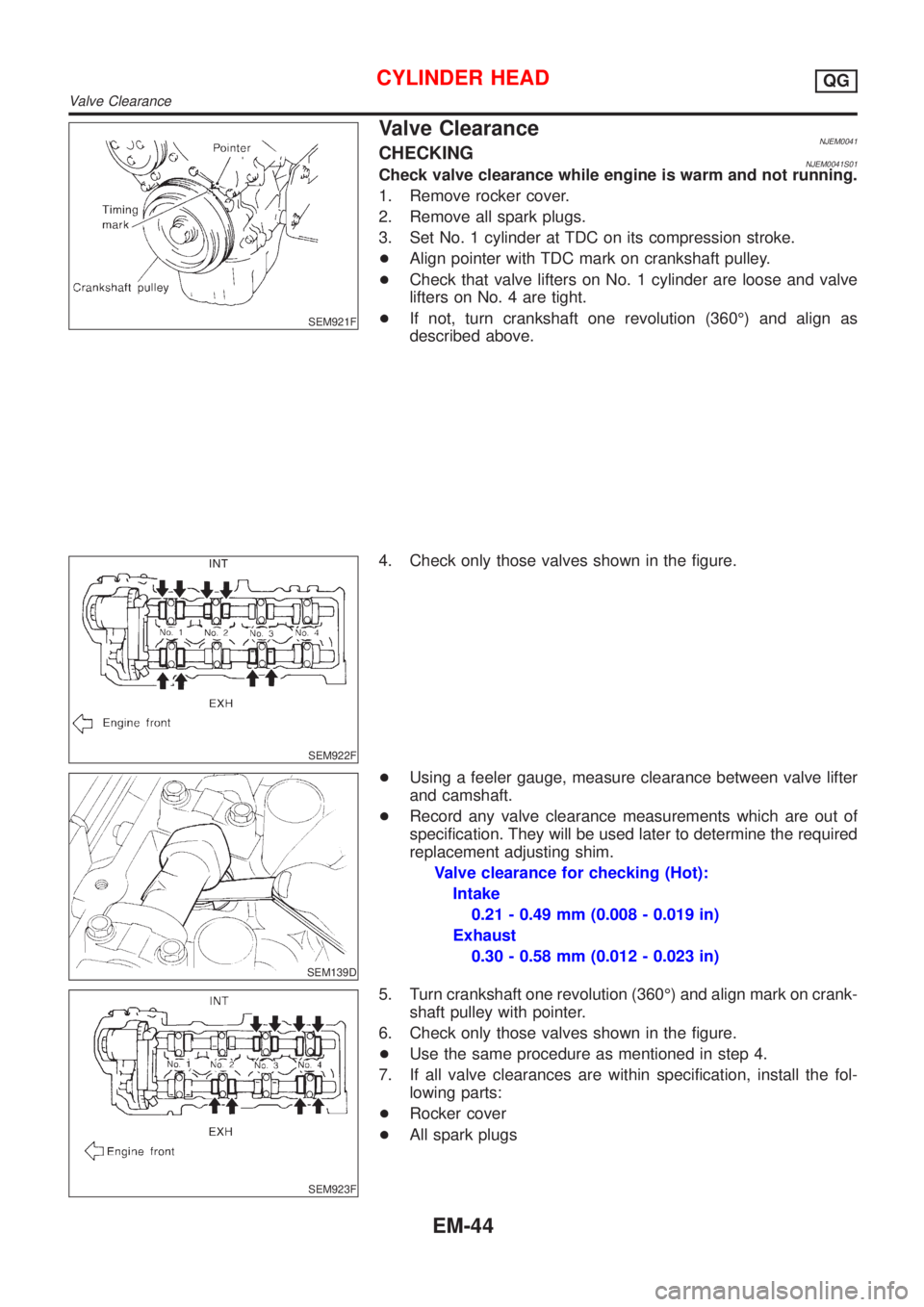
Valve ClearanceNJEM0041CHECKINGNJEM0041S01Check valve clearance while engine is warm and not running.
1. Remove rocker cover.
2. Remove all spark plugs.
3. Set No. 1 cylinder at TDC on its compression stroke.
+Align pointer with TDC mark on crankshaft pulley.
+Check that valve lifters on No. 1 cylinder are loose and valve
lifters on No. 4 are tight.
+If not, turn crankshaft one revolution (360É) and align as
described above.
SEM922F
4. Check only those valves shown in the figure.
SEM139D
+Using a feeler gauge, measure clearance between valve lifter
and camshaft.
+Record any valve clearance measurements which are out of
specification. They will be used later to determine the required
replacement adjusting shim.
Valve clearance for checking (Hot):
Intake
0.21 - 0.49 mm (0.008 - 0.019 in)
Exhaust
0.30 - 0.58 mm (0.012 - 0.023 in)
SEM923F
5. Turn crankshaft one revolution (360É) and align mark on crank-
shaft pulley with pointer.
6. Check only those valves shown in the figure.
+Use the same procedure as mentioned in step 4.
7. If all valve clearances are within specification, install the fol-
lowing parts:
+Rocker cover
+All spark plugs
CYLINDER HEADQG
Valve Clearance
EM-44
Page 2558 of 2898

NJMA0043
The following tables show the normal maintenance schedule. Depending upon weather and atmospheric
conditions, varying road surfaces, individual driving habits and vehicle usage, additional or more frequent
maintenance may be required.
Periodic maintenance beyond the last period shown on the tables requires similar maintenance.
Maintenance Schedule for Petrol Engines
(Annual Mileage < 30,000 km/year)
NJMA0043S01QG15DE/QG18DE ENGINESNJMA0043S0101Abbreviations: R = Replace I = Inspect: Correct or replace if necessary
MAINTENANCE OPERATIONMAINTENANCE INTERVAL
Refer-
ence
pages Perform on a kilometer basis, but on
an annual basis when driving less than
15,000 km (9,000 miles) per yearkm x 1,000
(miles x 1,000)
Months15
(9)
1230
(18)
2445
(27)
3660
(36)
4875
(45)
6090
(54)
72105
(63)
84120
(72)
96
Engine compartment and under vehicle
Engine oil (Use recommended oil)HRRRRRRRRLC-8
Engine oil filter (Use NISSAN genuine
part or equivalent)HRRRRRRRRLC-9
Drive beltsIIIIIIIIEM-16
Cooling systemIIIIIIIILC-12
Engine anti-freeze coolant (Use genu-
ine NISSAN Anti-Freeze Coolant (L2N)
or equivalent)See NOTE (1) I R I LC-18
Air cleaner filterHR R EM-18
Intake and exhaust valve clearance See NOTE (2) EM-44
Fuel and EVAP vapour linesIIIIFE-5/
EC-36
Spark plugsRRRREM-19
Fuel filter See NOTE (3) FE-12
Heated oxygen sensor (Exhaust gas
sensor)HSee NOTE (4)GI-40,
EC-47
NOTE:
(1) First replace at 90,000 km (54,000 miles)/60 months, then every 60,000 km (36,000 miles)/48 months. Perform ªIº (Check-
ing the mixture ratio and correcting the mixture ratio if necessary) at the middle of replacement interval.
(2) Periodic maintenance is not required. However, if valve noise increases, check valve clearance.
(3) Fuel filter is maintenance-free. For service procedures, refer to FE section.
(4) Perform only according to ªMaintenance Under Severe Driving Conditionsº for models without Euro-OBD system. For
models with Euro-OBD system, periodic maintenance is not required.
HMaintenance items with ªHº should be performed more frequently according to ªMaintenance Under Severe Driving Con-
ditionsº.
PERIODIC MAINTENANCE (FOR EUROPE)
Maintenance Schedule for Petrol Engines (Annual Mileage < 30,000 km/year)
MA-4
Page 2564 of 2898
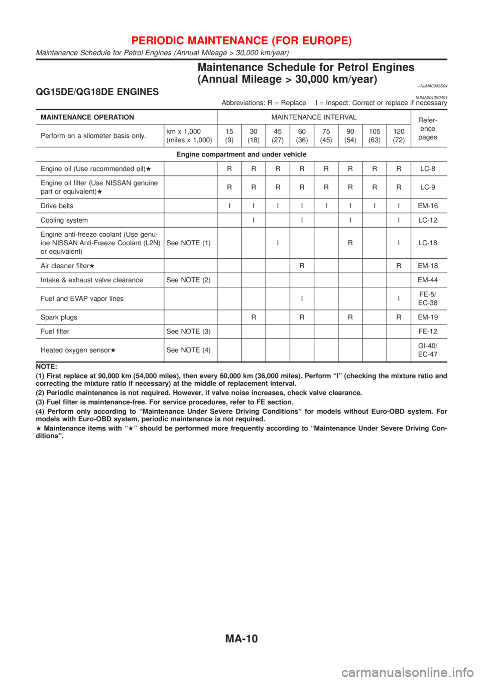
Maintenance Schedule for Petrol Engines
(Annual Mileage > 30,000 km/year)
=NJMA0043S04QG15DE/QG18DE ENGINESNJMA0043S0401Abbreviations: R = Replace I = Inspect: Correct or replace if necessary
MAINTENANCE OPERATIONMAINTENANCE INTERVAL
Refer-
ence
pages Perform on a kilometer basis only.km x 1,000
(miles x 1,000)15
(9)30
(18)45
(27)60
(36)75
(45)90
(54)105
(63)120
(72)
Engine compartment and under vehicle
Engine oil (Use recommended oil)HRRRRRRRRLC-8
Engine oil filter (Use NISSAN genuine
part or equivalent)HRRRRRRRRLC-9
Drive beltsIIIIIIIIEM-16
Cooling systemIIIILC-12
Engine anti-freeze coolant (Use genu-
ine NISSAN Anti-Freeze Coolant (L2N)
or equivalent)See NOTE (1) I R I LC-18
Air cleaner filterHR R EM-18
Intake & exhaust valve clearance See NOTE (2) EM-44
Fuel and EVAP vapor lines I IFE-5/
EC-38
Spark plugsRRRREM-19
Fuel filter See NOTE (3) FE-12
Heated oxygen sensorHSee NOTE (4)GI-40/
EC-47
NOTE:
(1) First replace at 90,000 km (54,000 miles), then every 60,000 km (36,000 miles). Perform ªIº (checking the mixture ratio and
correcting the mixture ratio if necessary) at the middle of replacement interval.
(2) Periodic maintenance is not required. However, if valve noise increases, check valve clearance.
(3) Fuel filter is maintenance-free. For service procedures, refer to FE section.
(4) Perform only according to ªMaintenance Under Severe Driving Conditionsº for models without Euro-OBD system. For
models with Euro-OBD system, periodic maintenance is not required.
HMaintenance items with ªHº should be performed more frequently according to ªMaintenance Under Severe Driving Con-
ditionsº.
PERIODIC MAINTENANCE (FOR EUROPE)
Maintenance Schedule for Petrol Engines (Annual Mileage > 30,000 km/year)
MA-10