2001 NISSAN ALMERA parking sensors
[x] Cancel search: parking sensorsPage 518 of 2898

REAR DISC BRAKE (CAM & STRUT TYPE)..............35
Component ................................................................35
Pad Replacement ......................................................35
Removal .....................................................................37
Disassembly...............................................................37
Inspection...................................................................38
CALIPER.................................................................38
ROTOR...................................................................39
Assembly ...................................................................39
Installation ..................................................................42
REAR DISC BRAKE (BALL & RAMP TYPE)..............43
Component ................................................................43
Pad Replacement ......................................................43
Removal .....................................................................45
Disassembly...............................................................45
Inspection...................................................................45
CALIPER.................................................................45
ROTOR...................................................................46
Installation ..................................................................46
PARKING BRAKE CONTROL......................................47
Components...............................................................47
Removal and Installation ...........................................47
Inspection...................................................................47
Adjustment .................................................................48
ABS
DESCRIPTION...............................................................49
Purpose......................................................................49
ABS (Anti-Lock Brake System) Operation ................49
ABS Hydraulic Circuit ................................................49
System Components .................................................50
System Description ....................................................50
SENSOR.................................................................50
CONTROL UNIT......................................................50
ABS ACTUATOR AND ELECTRIC UNIT....................50
Component Parts and Harness Connector
Location .....................................................................52
Schematic/Sedan .......................................................53
Wiring Diagram - ABS -/Sedan..................................54
Schematic/Hatchback ................................................58
Wiring Diagram - ABS -/Hatchback ...........................59
MODELS WITH SELF-DIAGNOSIS FUNCTION
(DATA LINK CONNECTOR TERMINAL NO. 9)
...........59
MODELS WITHOUT SELF-DIAGNOSIS
FUNCTION (DATA LINK CONNECTOR TERMINAL
NO. 9)
.....................................................................60
ON BOARD DIAGNOSTIC SYSTEM
DESCRIPTION...............................................................63
Self-diagnosis (Only Models with Data Link
Connector Terminal No. 9) ........................................63
FUNCTION..............................................................63
SELF-DIAGNOSIS PROCEDURE..............................63
HOW TO READ SELF-DIAGNOSTIC RESULTS
(MALFUNCTION CODES)
........................................64
HOW TO ERASE SELF-DIAGNOSTIC RESULTS
(MALFUNCTION CODES)
........................................64
CONSULT-II ...............................................................65
CONSULT-II APPLICATION TO ABS..........................65
ECU (ABS CONTROL UNIT) PART NUMBER
MODE
.....................................................................65
CONSULT-II Inspection Procedure............................65
SELF-DIAGNOSIS PROCEDURE..............................65
SELF-DIAGNOSTIC RESULTS MODE.......................67
DATA MONITOR PROCEDURE................................68
ACTIVE TEST PROCEDURE....................................69
DATA MONITOR MODE...........................................70
ACTIVE TEST MODE...............................................70
TROUBLE DIAGNOSIS - INTRODUCTION..................71
How to Perform Trouble Diagnoses for Quick
and Accurate Repair ..................................................71
INTRODUCTION......................................................71
TROUBLE DIAGNOSIS - BASIC INSPECTION...........72
Preliminary Check......................................................72
Ground Circuit Check ................................................75
ABS ACTUATOR AND ELECTRIC UNIT GROUND.....75
TROUBLE DIAGNOSIS - GENERAL
DESCRIPTION...............................................................76
Malfunction Code/Symptom Chart.............................76
MODELS WITH SELF-DIAGNOSIS FUNCTION
(DATA LINK CONNECTOR TERMINAL NO. 9)
...........76
TROUBLE DIAGNOSES FOR SELF-DIAGNOSTIC
ITEMS.............................................................................78
Wheel Sensor or Rotor ..............................................78
DIAGNOSTIC PROCEDURE.....................................78
ABS Actuator Solenoid Valve or Solenoid Valve
Relay ..........................................................................81
DIAGNOSTIC PROCEDURE.....................................81
Motor Relay or Motor.................................................84
DIAGNOSTIC PROCEDURE.....................................84
Low Voltage ...............................................................86
DIAGNOSTIC PROCEDURE.....................................86
Control Unit ................................................................88
DIAGNOSTIC PROCEDURE.....................................88
TROUBLE DIAGNOSES FOR SYMPTOMS.................89
1. ABS Works Frequently ..........................................89
2. Unexpected Pedal Action ......................................89
3. Long Stopping Distance ........................................90
4. ABS Does Not Work ..............................................91
5. Pedal Vibration and Noise.....................................92
6. ABS Warning Lamp Does Not Come On
When Ignition Switch Is Turned On...........................93
7. ABS Warning Lamp Stays On When Ignition
Switch Is Turned On ..................................................95
REMOVAL AND INSTALLATION.................................97
Wheel Sensors ..........................................................97
ABS Actuator and Electric Unit..................................98
CONTENTS(Cont'd)
BR-2
Page 2012 of 2898

for example, when the vehicle is in a tunnel, in a parking lot
inside building, under an elevated superhighway or near strong
power lines, the location may not be detected. Turbulent/
electric weather conditions may also affect positioning perfor-
mance. If something is placed on the antenna, the radio wave
from GPS satellites may not be received.
SEL507X
COMPONENT DESCRIPTIONNJEL0516S02NAVI Control UnitNJEL0516S0201+The gyro (angular speed sensor) and the CD-ROM drive are
built-in units that control the navigation functions.
+Signals are received from the gyro, the vehicle speed sensor,
and the GPS antenna. Vehicle location is determined by com-
bining this data with the data contained in the CD-ROM map.
Locational information is shown on liquid crystal display panel.
SEL506X
CD-ROM DriverNJEL0516S0202Maps, traffic control regulations, and other pertinent information
can be easily red from the CD-ROM disc.
Map CD-ROMNJEL0516S0203+The map CD-ROM has maps, traffic control regulations, and
other pertinent information.
+To improve CD-ROM map matching and route determination
functions, the CD-ROM uses an exclusive Nissan format.
Therefore, the use of a CD-ROM provided by other manufac-
turers cannot be used.
SEL690V
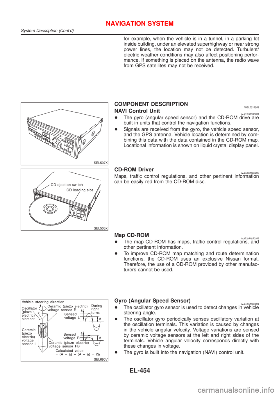
Gyro (Angular Speed Sensor)NJEL0516S0204+The oscillator gyro sensor is used to detect changes in vehicle
steering angle.
+The oscillator gyro periodically senses oscillatory variation at
the oscillation terminals. This variation is caused by changes
in the vehicle angular velocity. Voltage variations are sensed
by ceramic voltage sensors at the left and right sides of the
terminals. Vehicle angular velocity corresponds directly with
these changes in voltage.
+The gyro is built into the navigation (NAVI) control unit.
NAVIGATION SYSTEM
System Description (Cont'd)
EL-454