2001 NISSAN ALMERA battery location
[x] Cancel search: battery locationPage 907 of 2898
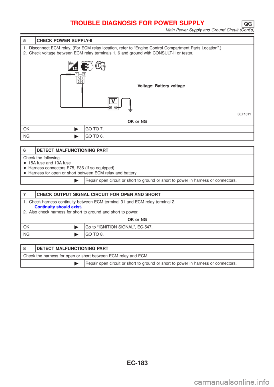
5 CHECK POWER SUPPLY-II
1. Disconnect ECM relay. (For ECM relay location, refer to ªEngine Control Compartment Parts Locationº.)
2. Check voltage between ECM relay terminals 1, 6 and ground with CONSULT-II or tester.
SEF101Y
OK or NG
OK©GO TO 7.
NG©GO TO 6.
6 DETECT MALFUNCTIONING PART
Check the following.
+15A fuse and 10A fuse
+Harness connectors E75, F36 (If so equipped)
+Harness for open or short between ECM relay and battery
©Repair open circuit or short to ground or short to power in harness or connectors.
7 CHECK OUTPUT SIGNAL CIRCUIT FOR OPEN AND SHORT
1. Check harness continuity between ECM terminal 31 and ECM relay terminal 2.
Continuity should exist.
2. Also check harness for short to ground and short to power.
OK or NG
OK©Go to ªIGNITION SIGNALº, EC-547.
NG©GO TO 8.
8 DETECT MALFUNCTIONING PART
Check the harness for open or short between ECM relay and ECM.
©Repair open circuit or short to ground or short to power in harness or connectors.
TROUBLE DIAGNOSIS FOR POWER SUPPLYQG
Main Power Supply and Ground Circuit (Cont'd)
EC-183
Page 1394 of 2898
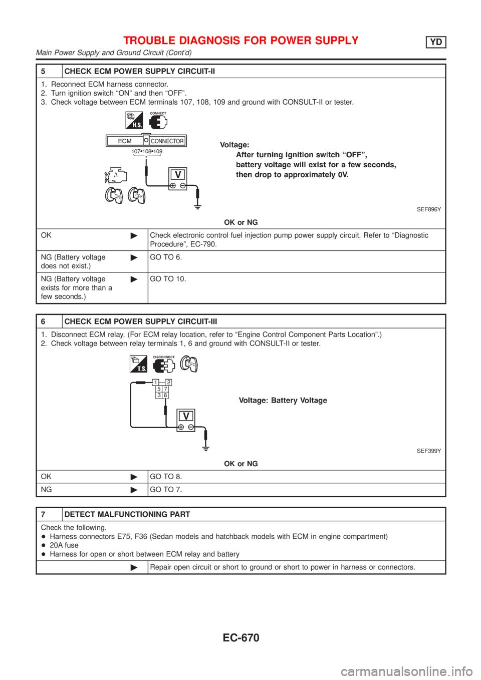
5 CHECK ECM POWER SUPPLY CIRCUIT-II
1. Reconnect ECM harness connector.
2. Turn ignition switch ªONº and then ªOFFº.
3. Check voltage between ECM terminals 107, 108, 109 and ground with CONSULT-II or tester.
SEF896Y
OK or NG
OK©Check electronic control fuel injection pump power supply circuit. Refer to ªDiagnostic
Procedureº, EC-790.
NG (Battery voltage
does not exist.)©GO TO 6.
NG (Battery voltage
exists for more than a
few seconds.)©GO TO 10.
6 CHECK ECM POWER SUPPLY CIRCUIT-III
1. Disconnect ECM relay. (For ECM relay location, refer to ªEngine Control Component Parts Locationº.)
2. Check voltage between relay terminals 1, 6 and ground with CONSULT-II or tester.
SEF399Y
OK or NG
OK©GO TO 8.
NG©GO TO 7.
7 DETECT MALFUNCTIONING PART
Check the following.
+Harness connectors E75, F36 (Sedan models and hatchback models with ECM in engine compartment)
+20A fuse
+Harness for open or short between ECM relay and battery
©Repair open circuit or short to ground or short to power in harness or connectors.
TROUBLE DIAGNOSIS FOR POWER SUPPLYYD
Main Power Supply and Ground Circuit (Cont'd)
EC-670
Page 1521 of 2898
Diagnostic ProcedureNJEC0748
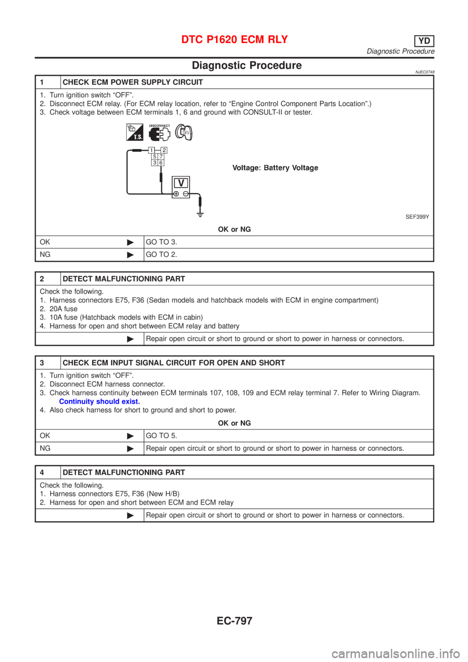
1 CHECK ECM POWER SUPPLY CIRCUIT
1. Turn ignition switch ªOFFº.
2. Disconnect ECM relay. (For ECM relay location, refer to ªEngine Control Component Parts Locationº.)
3. Check voltage between ECM terminals 1, 6 and ground with CONSULT-II or tester.
SEF399Y
OK or NG
OK©GO TO 3.
NG©GO TO 2.
2 DETECT MALFUNCTIONING PART
Check the following.
1. Harness connectors E75, F36 (Sedan models and hatchback models with ECM in engine compartment)
2. 20A fuse
3. 10A fuse (Hatchback models with ECM in cabin)
4. Harness for open and short between ECM relay and battery
©Repair open circuit or short to ground or short to power in harness or connectors.
3 CHECK ECM INPUT SIGNAL CIRCUIT FOR OPEN AND SHORT
1. Turn ignition switch ªOFFº.
2. Disconnect ECM harness connector.
3. Check harness continuity between ECM terminals 107, 108, 109 and ECM relay terminal 7. Refer to Wiring Diagram.
Continuity should exist.
4. Also check harness for short to ground and short to power.
OK or NG
OK©GO TO 5.
NG©Repair open circuit or short to ground or short to power in harness or connectors.
4 DETECT MALFUNCTIONING PART
Check the following.
1. Harness connectors E75, F36 (New H/B)
2. Harness for open and short between ECM and ECM relay
©Repair open circuit or short to ground or short to power in harness or connectors.
DTC P1620 ECM RLYYD
Diagnostic Procedure
EC-797
Page 1544 of 2898
3 CHECK EGR VOLUME CONTROL VALVE POWER SUPPLY CIRCUIT-II
1. Turn ignition switch ªOFFº.
2. Disconnect ECM relay. (For ECM relay location, refer to ªEngine Control Component Parts Locationº.)
3. Check harness continuity between ECM relay terminal 5 and EGR volume control valve terminals 2 and 5. Refer to
Wiring Diagram.
Continuity should exist.
OK or NG
OK©GO TO 4.
NG©Repair open circuit or short to ground or short to power in harness or connectors.
4 CHECK EGR VOLUME CONTROL VALVE POWER SUPPLY CIRCUIT-III
Check voltage between ECM relay terminal 3 and ground with CONSULT-II or tester.
SEF413Y
OK or NG
OK©GO TO 6.
NG©GO TO 5.
5 DETECT MALFUNCTIONING PART
Check the following.
+Harness connectors E75, F36 (Sedan models and hatchback models with ECM in engine compartment)
+10A fuse
+Harness for open or short between ECM relay and battery
©Repair open circuit or short to ground or short to power in harness or connectors.
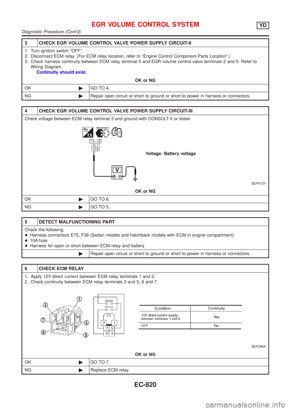
6 CHECK ECM RELAY
1. Apply 12V direct current between ECM relay terminals 1 and 2.
2. Check continuity between ECM relay terminals 3 and 5, 6 and 7.
SEF296X
OK or NG
OK©GO TO 7.
NG©Replace ECM relay.
EGR VOLUME CONTROL SYSTEMYD
Diagnostic Procedure (Cont'd)
EC-820
Page 1561 of 2898
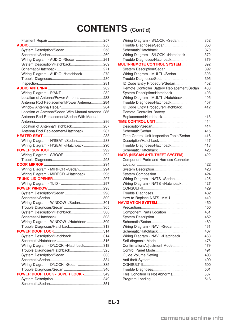
Filament Repair .......................................................257
AUDIO..........................................................................258
System Description/Sedan ......................................258
Schematic/Sedan .....................................................260
Wiring Diagram - AUDIO -/Sedan ...........................261
System Description/Hatchback ................................269
Schematic/Hatchback ..............................................271
Wiring Diagram - AUDIO -/Hatchback .....................272
Trouble Diagnoses...................................................280
Inspection.................................................................281
AUDIO ANTENNA.......................................................282
Wiring Diagram - P/ANT - .......................................282
Location of Antenna/Power Antenna .......................283
Antenna Rod Replacement/Power Antenna ............284
Window Antenna Repair ..........................................284
Location of Antenna/Sedan With Manual Antenna..286
Antenna Rod Replacement/Sedan With Manual
Antenna....................................................................286
Location of Antenna/Hatchback ...............................287
Antenna Rod Replacement/Hatchback ...................287
HEATED SEAT............................................................288
Wiring Diagram - H/SEAT -/Sedan ..........................288
Wiring Diagram - H/SEAT -/Hatchback ...................290
POWER SUNROOF.....................................................292
Wiring Diagram - SROOF - .....................................292
Trouble Diagnoses...................................................293
DOOR MIRROR...........................................................294
Wiring Diagram - MIRROR -/Sedan ........................294
Wiring Diagram - MIRROR -/Hatchback .................295
TRUNK LID OPENER..................................................297
Wiring Diagram - TLID - ..........................................297
POWER WINDOW.......................................................298
System Description/Sedan ......................................298
Schematic/Sedan .....................................................300
Wiring Diagram - WINDOW -/Sedan .......................301
Trouble Diagnoses/Sedan .......................................305
System Description/Hatchback ................................306
Schematic/Hatchback ..............................................308
Wiring Diagram - WINDOW -/Hatchback ................309
Trouble Diagnoses/Hatchback.................................313
POWER DOOR LOCK.................................................314
System Description/Hatchback ................................314
Schematic/Hatchback ..............................................316
Wiring Diagram - D/LOCK -/Hatchback...................318
Trouble Diagnoses/Hatchback.................................325
System Description/Sedan ......................................333
Schematic/Sedan .....................................................334
Wiring Diagram - D/LOCK -/Sedan .........................335
Trouble Diagnoses/Sedan .......................................340
POWER DOOR LOCK - SUPER LOCK -...................349
System Description ..................................................349
Schematic/Sedan .....................................................351Wiring Diagram - S/LOCK -/Sedan .........................352
Trouble Diagnoses/Sedan .......................................358
Schematic/Hatchback ..............................................370
Wiring Diagram - S/LOCK -/Hatchback ...................372
Trouble Diagnoses/Hatchback.................................379
MULTI-REMOTE CONTROL SYSTEM.......................392
System Description/Sedan ......................................392
Wiring Diagram - MULTI -/Sedan ............................393
Trouble Diagnoses/Sedan .......................................395
ID Code Entry Procedure/Sedan .............................402
Remote Controller Battery Replacement/Sedan .....403
System Description/Hatchback ................................403
Wiring Diagram - MULTI -/Hatchback .....................405
Trouble Diagnoses/Hatchback.................................407
ID Code Entry Procedure/Hatchback ......................412
Remote Controller Battery
Replacement/Hatchback ..........................................413
TIME CONTROL UNIT................................................414
Description/Sedan....................................................414
Schematic/Sedan .....................................................415
Time Control Unit Inspection Table/Sedan ..............416
Description/Hatchback .............................................417
Trouble Diagnoses/Hatchback.................................418
Schematic/Hatchback ..............................................420
NATS (NISSAN ANTI-THEFT SYSTEM).....................422
Component Parts and Harness Connetor
Location ...................................................................422
System Description ..................................................423
System Composition ................................................424
Wiring Diagram - NATS -/Sedan .............................425
Wiring Diagram - NATS -/Hatchback.......................427
CONSULT-II .............................................................429
Trouble Diagnoses...................................................432
How to Replace NATS IMMU ..................................449
NAVIGATION SYSTEM...............................................450
Precautions ..............................................................450
Component Parts Location ......................................451
System Description ..................................................452
Schematic/Sedan .....................................................460
Wiring Diagram - NAVI -/Sedan ..............................461
Schematic/Hatchback ..............................................467
Wiring Diagram - NAVI -/Hatchback ........................468
Self-diagnosis Mode ................................................476
Confirmation/Adjustment Mode ...............................479
Control Panel Mode .................................................491
Guide Volume Setting ..............................................498
Anti-theft System .....................................................499
CONSULT-II .............................................................500
Trouble Diagnoses...................................................501
This Condition Is Not Abnormal...............................507
Program Loading .....................................................516
CONTENTS(Cont'd)
EL-3
Page 1702 of 2898
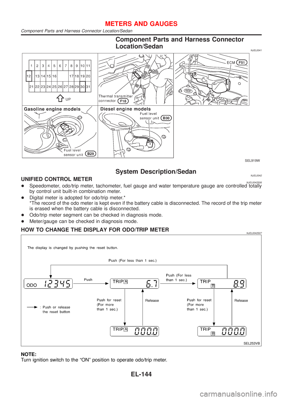
Component Parts and Harness Connector
Location/Sedan
NJEL0041
SEL919W
System Description/SedanNJEL0042UNIFIED CONTROL METERNJEL0042S06+Speedometer, odo/trip meter, tachometer, fuel gauge and water temperature gauge are controlled totally
by control unit built-in combination meter.
+Digital meter is adopted for odo/trip meter.*
*The record of the odo meter is kept even if the battery cable is disconnected. The record of the trip meter
is erased when the battery cable is disconnected.
+Odo/trip meter segment can be checked in diagnosis mode.
+Meter/gauge can be checked in diagnosis mode.
HOW TO CHANGE THE DISPLAY FOR ODO/TRIP METERNJEL0042S07
SEL253VB
NOTE:
Turn ignition switch to the ªONº position to operate odo/trip meter.
METERS AND GAUGES
Component Parts and Harness Connector Location/Sedan
EL-144
Page 1722 of 2898
Component Parts and Harness Connector
Location/Hatchback
=NJEL0441For details, refer to ªELECTRICAL UNITS LOCATIONº (EL-517)
and ªHARNESS LAYOUTº (EL-522).
System Description/HatchbackNJEL0442UNIFIED CONTROL METERNJEL0442S01+Speedometer, odo/trip meter, tachometer, fuel gauge and water temperature gauge are controlled totally
by control unit built-in combination meter.
+Digital meter is adopted for odo/trip meter.*
*The record of the odo meter is kept even if the battery cable is disconnected. The record of the trip meter
is erased when the battery cable is disconnected.
+Odo/trip meter segment can be checked in diagnosis mode.
+Meter/gauge can be checked in diagnosis mode.
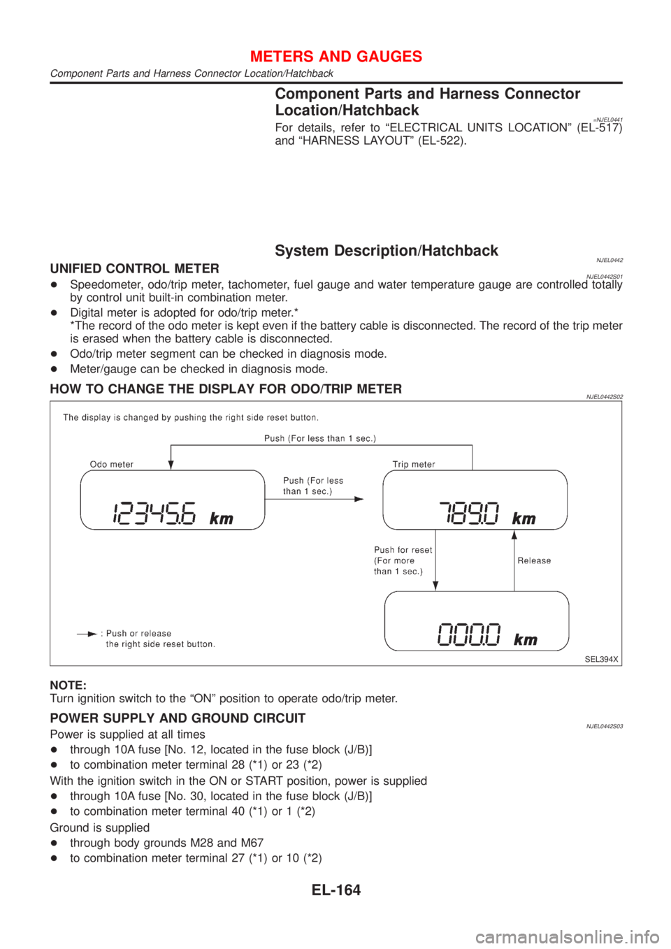
HOW TO CHANGE THE DISPLAY FOR ODO/TRIP METERNJEL0442S02
SEL394X
NOTE:
Turn ignition switch to the ªONº position to operate odo/trip meter.
POWER SUPPLY AND GROUND CIRCUITNJEL0442S03Power is supplied at all times
+through 10A fuse [No. 12, located in the fuse block (J/B)]
+to combination meter terminal 28 (*1) or 23 (*2)
With the ignition switch in the ON or START position, power is supplied
+through 10A fuse [No. 30, located in the fuse block (J/B)]
+to combination meter terminal 40 (*1) or 1 (*2)
Ground is supplied
+through body grounds M28 and M67
+to combination meter terminal 27 (*1) or 10 (*2)
METERS AND GAUGES
Component Parts and Harness Connector Location/Hatchback
EL-164
Page 2059 of 2898
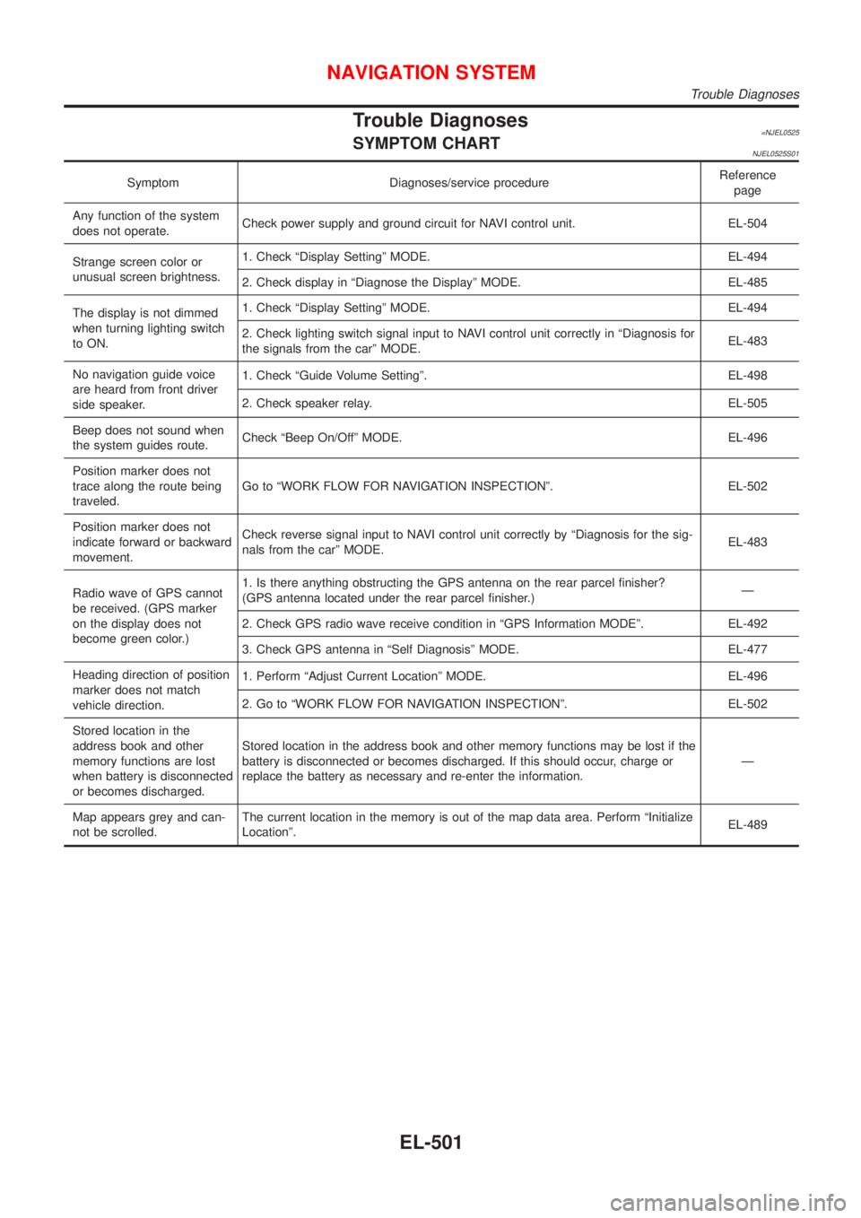
Trouble Diagnoses=NJEL0525SYMPTOM CHARTNJEL0525S01
Symptom Diagnoses/service procedureReference
page
Any function of the system
does not operate.Check power supply and ground circuit for NAVI control unit. EL-504
Strange screen color or
unusual screen brightness.1. Check ªDisplay Settingº MODE. EL-494
2. Check display in ªDiagnose the Displayº MODE. EL-485
The display is not dimmed
when turning lighting switch
to ON.1. Check ªDisplay Settingº MODE. EL-494
2. Check lighting switch signal input to NAVI control unit correctly in ªDiagnosis for
the signals from the carº MODE.EL-483
No navigation guide voice
are heard from front driver
side speaker.1. Check ªGuide Volume Settingº. EL-498
2. Check speaker relay. EL-505
Beep does not sound when
the system guides route.Check ªBeep On/Offº MODE. EL-496
Position marker does not
trace along the route being
traveled.Go to ªWORK FLOW FOR NAVIGATION INSPECTIONº. EL-502
Position marker does not
indicate forward or backward
movement.Check reverse signal input to NAVI control unit correctly by ªDiagnosis for the sig-
nals from the carº MODE.EL-483
Radio wave of GPS cannot
be received. (GPS marker
on the display does not
become green color.)1. Is there anything obstructing the GPS antenna on the rear parcel finisher?
(GPS antenna located under the rear parcel finisher.)Ð
2. Check GPS radio wave receive condition in ªGPS Information MODEº. EL-492
3. Check GPS antenna in ªSelf Diagnosisº MODE. EL-477
Heading direction of position
marker does not match
vehicle direction.1. Perform ªAdjust Current Locationº MODE. EL-496
2. Go to ªWORK FLOW FOR NAVIGATION INSPECTIONº. EL-502
Stored location in the
address book and other
memory functions are lost
when battery is disconnected
or becomes discharged.Stored location in the address book and other memory functions may be lost if the
battery is disconnected or becomes discharged. If this should occur, charge or
replace the battery as necessary and re-enter the information.Ð
Map appears grey and can-
not be scrolled.The current location in the memory is out of the map data area. Perform ªInitialize
Locationº.EL-489
NAVIGATION SYSTEM
Trouble Diagnoses
EL-501