2001 NISSAN ALMERA hood open
[x] Cancel search: hood openPage 624 of 2898

Checking Body CorrosionNJBT0033Visually check the body sheet metal panel for corrosion, paint damage (scratches, chipping, rubbing, etc.) or
damage to the anti-corrosion materials. In particular, check the following locations.
Hemmed portion
Hood front end, door lower end, trunk lid rear end, etc.
Panel joint
Side sill of rear fender and center pillar, rear wheel housing of rear fender, around strut tower in engine
compartment, etc.
Panel edge
Trunk lid opening, sunroof opening, fender wheelarch flange, fuel filler lid flange, around holes in panel, etc.
Parts contact
Waist molding, windshield molding, bumper, etc.
Protectors
Damage or condition of mudguard, fender protector, chipping protector, etc.
Anti-corrosion materials
Damage or separation of anti-corrosion materials under the body.
Drain holes
Condition of drain holes at door and side sill.
When repairing corroded areas, refer to the Corrosion Repair Manual.
CHASSIS AND BODY MAINTENANCE (FOR EUROPE)
Checking Body Corrosion
BT-6
Page 625 of 2898

Removal and InstallationNJBT0004+When removing or installing hood, place a cloth or other padding on hood. This prevents vehicle body from
being scratched.
+Bumper fascia is made of plastic. Do not use excessive force and be sure to keep oil away from it.
+Hood adjustment: Adjust at hinge portion.
+Hood lock adjustment: After adjusting, check hood lock control operation. Apply a coat of grease to hood
locks engaging mechanism.
+Hood opener: Do not attempt to bend cable forcibly. Doing so increases effort required to unlock hood.
FRONT BUMPER ASSEMBLYNJBT0004S011. Remove clips securing front grille, then remove front grille.
2. Remove front turn signal lamp, then disconnect harness connectors.
3. Remove clips and screws securing left and right sides of fender protectors.
4. Remove clips and screws securing left and right sides of fender protectors in wheelhoulse.
5. Remove screws securing left and right front fenders to bumper fascia.
6. Remove screws securing left and right radiator core support side to bumper fascia.
7. Remove bolts securing radiator core support lower to bumper fascia.
8. Remove clips securing radiator core support upper to bumper fascia.
9. Extract bumper fascia assembly. Then disconnect harness connectors. (Models with fog lamp assembly)
10. Remove energy absorber. (Where fitted)
11. Remove bolts and hooks securing the headlamp assembly, then disconnect harness connectors.
12. Remove nuts securing bumper reinforcement to left and right bumper stays.(Where fitted)
13. Extract bumper reinforcement. (Where fitted)
14. Remove bolts securing bumper upper retainer, then remove bumper upper retainer.
15. Remove bolts securing bumper stays, then remove the bumper stays.
Fog lamp assembly (Models with fog lamp assembly)
16. Remove bolt securing fog lamp assembly.
17. Extract fog lamp assembly.
NBT182
BODY FRONT END
Removal and Installation
BT-7
Page 771 of 2898

Inspection ProcedureNJEC0593
1 INSPECTION START
1. Visually check the following:
+Air cleaner clogging
+Hoses and ducts for leaks
+EGR valve operation
+Electrical connectors
+Gasket
+Throttle valve and throttle position sensor operation
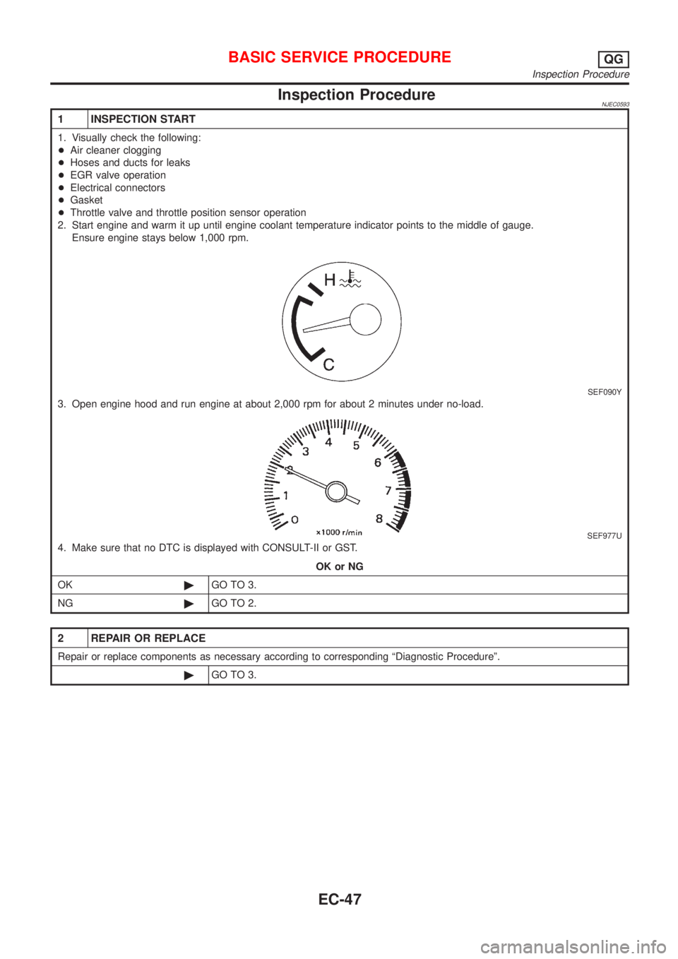
2. Start engine and warm it up until engine coolant temperature indicator points to the middle of gauge.
Ensure engine stays below 1,000 rpm.
SEF090Y
3. Open engine hood and run engine at about 2,000 rpm for about 2 minutes under no-load.
SEF977U
4. Make sure that no DTC is displayed with CONSULT-II or GST.
OK or NG
OK©GO TO 3.
NG©GO TO 2.
2 REPAIR OR REPLACE
Repair or replace components as necessary according to corresponding ªDiagnostic Procedureº.
©GO TO 3.
BASIC SERVICE PROCEDUREQG
Inspection Procedure
EC-47
Page 824 of 2898

Basic Inspection/SedanNJEC1736Precaution:
Perform Basic Inspection without electrical or mechanical
loads applied;
+Headlamp switch is OFF,
On vehicle equipped with daytime light systems, set lighting
switch to the 1st position to light only small lamps.
+Air conditioner switch is OFF,
+Rear window defogger switch is OFF,
+Steering wheel is in the straight-ahead position, etc.
MODELS WITH THROTTLE POSITION SWITCHNJEC1736S01
1 INSPECTION START
1. Check service records for any recent repairs that may indicate a related problem, or a current need for scheduled
maintenance.
2. Open engine hood and check the following:
+Harness connectors for improper connections
+Vacuum hoses for splits, kinks and improper connections
+Wiring for improper connections, pinches and cuts
+Air cleaner clogging
+Hoses and ducts for leaks
SEF983U
©GO TO 2.
2 CHECK THROTTLE OPENER OPERATION-I
Confirm that there is a clearance between throttle drum and stopper.
SEF850Y
OK or NG
OK©GO TO 4.
NG©GO TO 3.
TROUBLE DIAGNOSIS Ð BASIC INSPECTIONQG
Basic Inspection/Sedan
EC-100
Page 840 of 2898

MODELS WITHOUT THROTTLE POSITION SWITCH=NJEC1736S02
1 INSPECTION START
1. Check service records for any recent repairs that may indicate a related problem, or a current need for scheduled
maintenance.
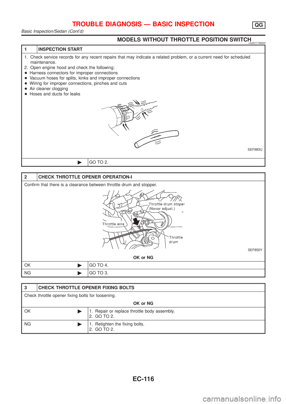
2. Open engine hood and check the following:
+Harness connectors for improper connections
+Vacuum hoses for splits, kinks and improper connections
+Wiring for improper connections, pinches and cuts
+Air cleaner clogging
+Hoses and ducts for leaks
SEF983U
©GO TO 2.
2 CHECK THROTTLE OPENER OPERATION-I
Confirm that there is a clearance between throttle drum and stopper.
SEF850Y
OK or NG
OK©GO TO 4.
NG©GO TO 3.
3 CHECK THROTTLE OPENER FIXING BOLTS
Check throttle opener fixing bolts for loosening.
OK or NG
OK©1. Repair or replace throttle body assembly.
2. GO TO 2.
NG©1. Retighten the fixing bolts.
2. GO TO 2.
TROUBLE DIAGNOSIS Ð BASIC INSPECTIONQG
Basic Inspection/Sedan (Cont'd)
EC-116
Page 852 of 2898

36 ERASE UNNECESSARY DTC
After this inspection, unnecessary DTC No. might be displayed.
Erase the stored memory in ECM and TCM (Transmission control module).
Refer to ªHow to Erase Emission-Related Diagnostic Informationº, EC-70 and AT-52, ªHOW TO ERASE DTCº.
©INSPECTION END
Basic Inspection/HatchbackNJEC1785MODELS WITH THROTTLE POSITION SWITCHNJEC1785S01Precaution:
Perform Basic Inspection without electrical or mechanical
loads applied;
+Headlamp switch is OFF,
On vehicle equipped with daytime light systems, set lighting
switch to the 1st position to light only small lamps.
+Air conditioner switch is OFF,
+Rear window defogger switch is OFF,
+Steering wheel is in the straight-ahead position, etc.
1 INSPECTION START
1. Check service records for any recent repairs that may indicate a related problem, or a current need for scheduled
maintenance.
2. Open engine hood and check the following:
+Harness connectors for improper connections
+Vacuum hoses for splits, kinks and improper connections
+Wiring for improper connections, pinches and cuts
+Air cleaner clogging
+Hoses and ducts for leaks
SEF983U
©GO TO 2.
TROUBLE DIAGNOSIS Ð BASIC INSPECTIONQG
Basic Inspection/Sedan (Cont'd)
EC-128
Page 868 of 2898

35 CHECK IGNITION TIMING AGAIN
Check ignition timing again. Refer to Test No. 31.
OK or NG
OK©GO TO 37.
NG©GO TO 36.
36 CHECK TIMING CHAIN INSTALLATION
Check timing chain installation. Refer to EM-28, ªInstallationº.
OK or NG
OK©GO TO 34.
NG©1. Repair the timing chain installation.
2. GO TO 32.
37 ERASE UNNECESSARY DTC
After this inspection, unnecessary DTC No. might be displayed.
Erase the stored memory in ECM and TCM (Transmission control module).
Refer to ªHow to Erase Emission-Related Diagnostic Informationº, EC-70 or EC-77 and AT-52, ªHOW TO ERASE DTCº.
OK or NG
©INSPECTION END
MODELS WITHOUT THROTTLE POSITION SWITCHNJEC1785S02Precaution:
Perform Basic Inspection without electrical or mechanical
loads applied;
+Headlamp switch is OFF,
On vehicle equipped with daytime light system, set lighting
switch to the 1st position to light only small lamps.
+Air conditioner switch is OFF,
+Rear window defogger switch is OFF,
+Steering wheel is in the straight-ahead position, etc.
1 INSPECTION START
1. Check service records for any recent repairs that may indicate a related problem, or a current need for scheduled
maintenance.
2. Open engine hood and check the following:
+Harness connectors for improper connections
+Vacuum hoses for splits, kinks and improper connections
+Wiring for improper connections, pinches and cuts
+Air cleaner clogging
+Hoses and ducts for leaks
SEF983U
©GO TO 2.
TROUBLE DIAGNOSIS Ð BASIC INSPECTIONQG
Basic Inspection/Hatchback (Cont'd)
EC-144
Page 1083 of 2898

SEF184UD
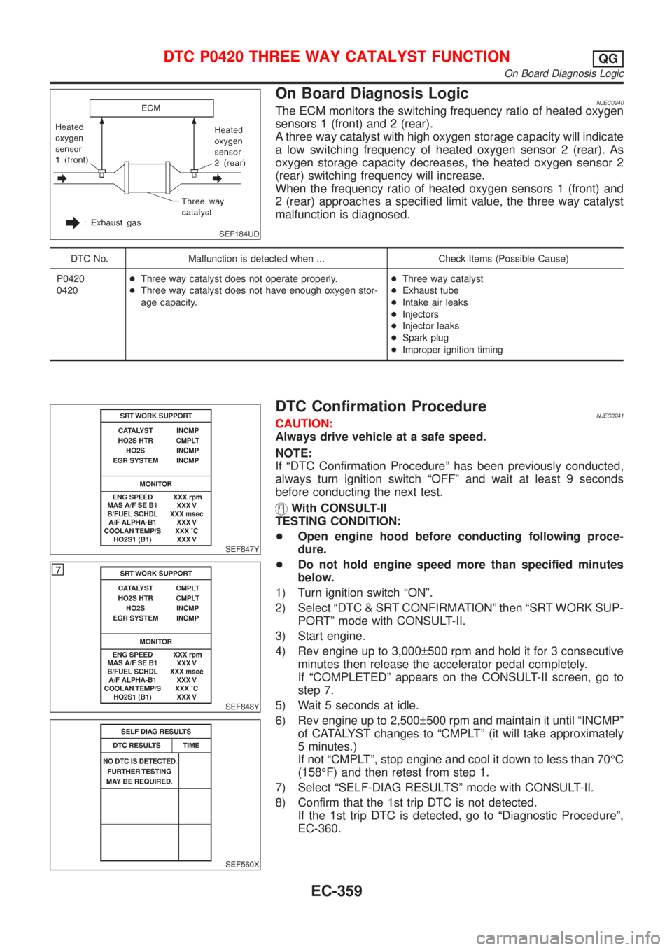
On Board Diagnosis LogicNJEC0240The ECM monitors the switching frequency ratio of heated oxygen
sensors 1 (front) and 2 (rear).
A three way catalyst with high oxygen storage capacity will indicate
a low switching frequency of heated oxygen sensor 2 (rear). As
oxygen storage capacity decreases, the heated oxygen sensor 2
(rear) switching frequency will increase.
When the frequency ratio of heated oxygen sensors 1 (front) and
2 (rear) approaches a specified limit value, the three way catalyst
malfunction is diagnosed.
DTC No. Malfunction is detected when ... Check Items (Possible Cause)
P0420
0420+Three way catalyst does not operate properly.
+Three way catalyst does not have enough oxygen stor-
age capacity.+Three way catalyst
+Exhaust tube
+Intake air leaks
+Injectors
+Injector leaks
+Spark plug
+Improper ignition timing
SEF847Y
SEF848Y
SEF560X
DTC Confirmation ProcedureNJEC0241CAUTION:
Always drive vehicle at a safe speed.
NOTE:
If ªDTC Confirmation Procedureº has been previously conducted,
always turn ignition switch ªOFFº and wait at least 9 seconds
before conducting the next test.
With CONSULT-II
TESTING CONDITION:
+Open engine hood before conducting following proce-
dure.
+Do not hold engine speed more than specified minutes
below.
1) Turn ignition switch ªONº.
2) Select ªDTC & SRT CONFIRMATIONº then ªSRT WORK SUP-
PORTº mode with CONSULT-II.
3) Start engine.
4) Rev engine up to 3,000±500 rpm and hold it for 3 consecutive
minutes then release the accelerator pedal completely.
If ªCOMPLETEDº appears on the CONSULT-II screen, go to
step 7.
5) Wait 5 seconds at idle.
6) Rev engine up to 2,500±500 rpm and maintain it until ªINCMPº
of CATALYST changes to ªCMPLTº (it will take approximately
5 minutes.)
If not ªCMPLTº, stop engine and cool it down to less than 70ÉC
(158ÉF) and then retest from step 1.
7) Select ªSELF-DIAG RESULTSº mode with CONSULT-II.
8) Confirm that the 1st trip DTC is not detected.
If the 1st trip DTC is detected, go to ªDiagnostic Procedureº,
EC-360.
DTC P0420 THREE WAY CATALYST FUNCTIONQG
On Board Diagnosis Logic
EC-359