2001 NISSAN ALMERA checking oil
[x] Cancel search: checking oilPage 82 of 2898

SAT767B
A/T Fluid CheckNJAT0025FLUID LEAKAGE CHECKNJAT0025S011. Clean area suspected of leaking. Ð for example, mating sur-
face of converter housing and transmission case.
2. Start engine, apply foot brake, place selector lever in ªDº posi-
tion and wait a few minutes.
3. Stop engine.
SAT288G
4. Check for fresh leakage.
SAT638A
FLUID CONDITION CHECKNJAT0025S02
Fluid color Suspected problem
Dark or black with burned odor Wear of frictional material
Milky pink Water contamination Ð Road water
entering through filler tube or breather
Varnished fluid, light to dark brown
and tackyOxidation Ð Over or under filling, Ð
Overheating
FLUID LEVEL CHECKNJAT0025S03Refer to ªChecking A/T Fluidº, AT-15.
SAT647B
Stall TestNJAT0026STALL TEST PROCEDURENJAT0026S011. Check A/T fluid and engine oil levels. If necessary, add.
2. Drive vehicle for approx. 10 minutes or until fluid and oil reach
operating temperature.
ATF operating temperature:
50 - 80ÉC (122 - 176ÉF)
TROUBLE DIAGNOSIS Ð BASIC INSPECTION
A/T Fluid Check
AT-80
Page 524 of 2898

SBR451D
Checking Brake Fluid LevelNJBR0006+Check fluid level in reservoir tank. It should be between Max
and Min lines on reservoir tank.
+If fluid level is extremely low, check brake system for leaks.
+Release parking brake lever and see if brake warning lamp
goes off. If not, check brake system for leaks.
SBR389C
Checking Brake LineNJBR0007CAUTION:
If leakage occurs around joints, retighten or, if necessary,
replace damaged parts.
1. Check brake lines (tubes and hoses) for cracks, deterioration
or other damage. Replace any damaged parts.
2. Check for oil leakage by fully depressing brake pedal while
engine is running.
SBR419C
Changing Brake FluidNJBR0008CAUTION:
+Refill with new brake fluid ªDOT 4º.
+Always keep fluid level higher than minimum line on res-
ervoir tank.
+Never reuse drained brake fluid.
+Be careful not to splash brake fluid on painted areas; it
may cause paint damage. If brake fluid is splashed on
painted areas, wash it away with water immediately.
1. Clean inside of reservoir tank, and refill with new brake fluid.
2. Connect a vinyl tube to each air bleeder valve.
3. Drain brake fluid from each air bleeder valve by depressing
brake pedal while keeping reservoir level higher than minimum
line by adding new brake fluid.
4. Repeat until new brake fluid comes out of each air bleeder
valve.
Use same procedure as in bleeding hydraulic system to refill
brake fluid. Refer to ªBleeding Brake Systemº, BR-9.
Brake Burnishing ProcedureNJBR0036Burnish the brake contact surfaces according to the following pro-
cedure after refinishing or replacing drums or rotors, after replac-
ing pads or linings, or if a soft pedal occurs at very low mileage.
CAUTION:
Only perform this procedure under safe road and traffic con-
ditions. Use extreme caution.
1. Drive the vehicle on a straight smooth road at 50 km/h (31
MPH).
2. Use medium brake pedal/foot effort to bring the vehicle to a
complete stop from 50 km/h (31 MPH). Adjust brake pedal/foot
ON-VEHICLE SERVICE
Checking Brake Fluid Level
BR-8
Page 1045 of 2898
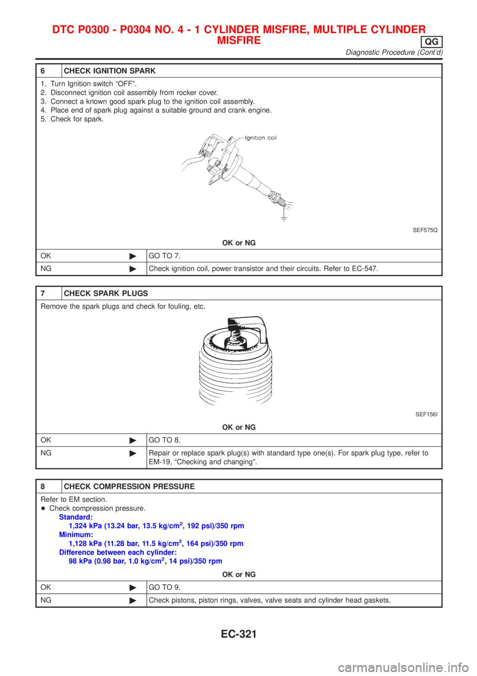
6 CHECK IGNITION SPARK
1. Turn Ignition switch ªOFFº.
2. Disconnect ignition coil assembly from rocker cover.
3. Connect a known good spark plug to the ignition coil assembly.
4. Place end of spark plug against a suitable ground and crank engine.
5. Check for spark.
SEF575Q
OK or NG
OK©GO TO 7.
NG©Check ignition coil, power transistor and their circuits. Refer to EC-547.
7 CHECK SPARK PLUGS
Remove the spark plugs and check for fouling, etc.
SEF156I
OK or NG
OK©GO TO 8.
NG©Repair or replace spark plug(s) with standard type one(s). For spark plug type, refer to
EM-19, ªChecking and changingº.
8 CHECK COMPRESSION PRESSURE
Refer to EM section.
+Check compression pressure.
Standard:
1,324 kPa (13.24 bar, 13.5 kg/cm
2, 192 psi)/350 rpm
Minimum:
1,128 kPa (11.28 bar, 11.5 kg/cm
2, 164 psi)/350 rpm
Difference between each cylinder:
98 kPa (0.98 bar, 1.0 kg/cm
2, 14 psi)/350 rpm
OK or NG
OK©GO TO 9.
NG©Check pistons, piston rings, valves, valve seats and cylinder head gaskets.
DTC P0300 - P0304 NO.4-1CYLINDER MISFIRE, MULTIPLE CYLINDER
MISFIRE
QG
Diagnostic Procedure (Cont'd)
EC-321
Page 2135 of 2898
ENGINE MECHANICAL
SECTION
EM
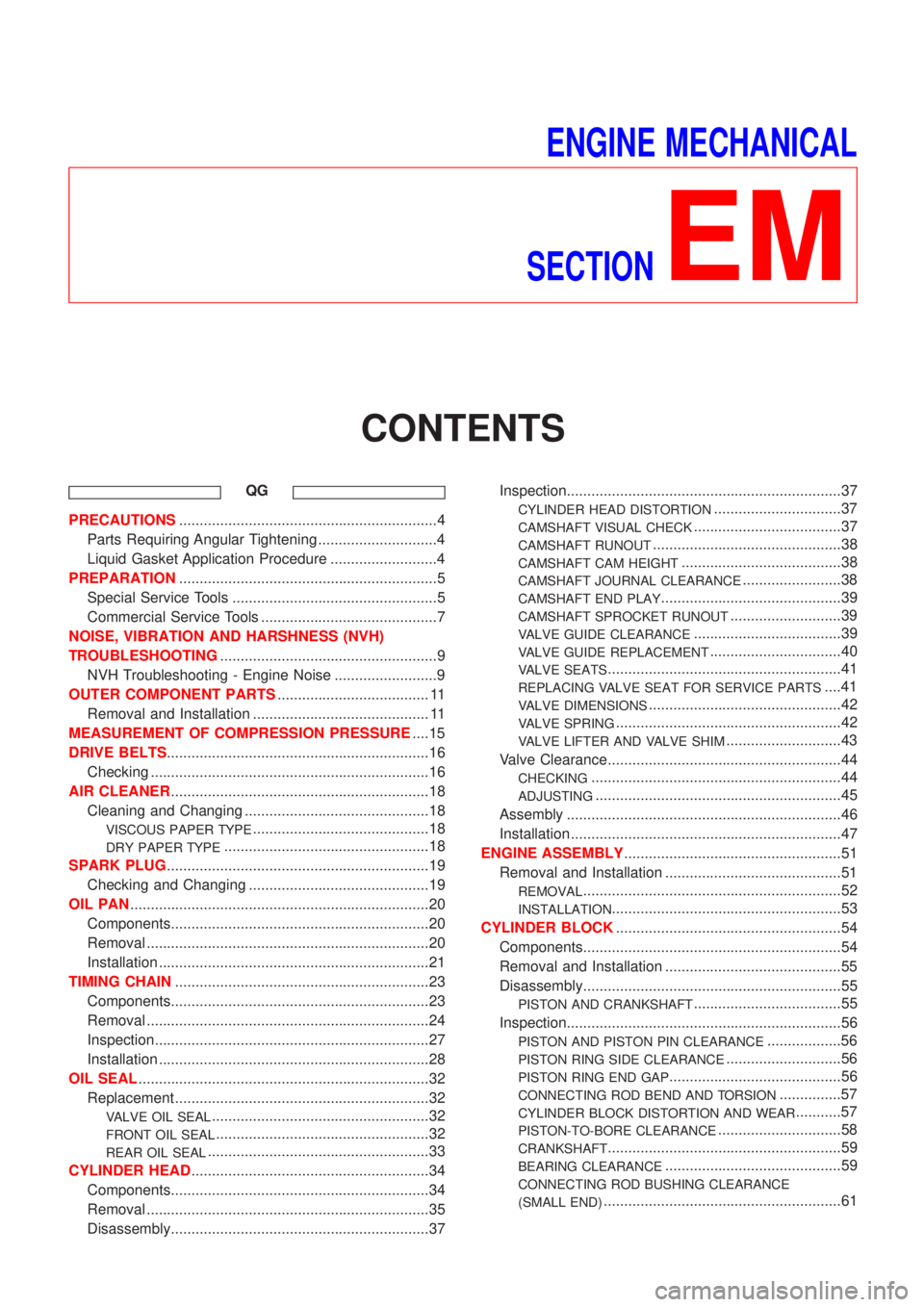
CONTENTS
QG
PRECAUTIONS...............................................................4
Parts Requiring Angular Tightening .............................4
Liquid Gasket Application Procedure ..........................4
PREPARATION...............................................................5
Special Service Tools ..................................................5
Commercial Service Tools ...........................................7
NOISE, VIBRATION AND HARSHNESS (NVH)
TROUBLESHOOTING.....................................................9
NVH Troubleshooting - Engine Noise .........................9
OUTER COMPONENT PARTS..................................... 11
Removal and Installation ........................................... 11
MEASUREMENT OF COMPRESSION PRESSURE....15
DRIVE BELTS................................................................16
Checking ....................................................................16
AIR CLEANER...............................................................18
Cleaning and Changing .............................................18
VISCOUS PAPER TYPE...........................................18
DRY PAPER TYPE..................................................18
SPARK PLUG................................................................19
Checking and Changing ............................................19
OIL PAN.........................................................................20
Components...............................................................20
Removal .....................................................................20
Installation ..................................................................21
TIMING CHAIN..............................................................23
Components...............................................................23
Removal .....................................................................24
Inspection...................................................................27
Installation ..................................................................28
OIL SEAL.......................................................................32
Replacement ..............................................................32
VALVE OIL SEAL.....................................................32
FRONT OIL SEAL....................................................32
REAR OIL SEAL......................................................33
CYLINDER HEAD..........................................................34
Components...............................................................34
Removal .....................................................................35
Disassembly...............................................................37Inspection...................................................................37
CYLINDER HEAD DISTORTION...............................37
CAMSHAFT VISUAL CHECK....................................37
CAMSHAFT RUNOUT..............................................38
CAMSHAFT CAM HEIGHT.......................................38
CAMSHAFT JOURNAL CLEARANCE........................38
CAMSHAFT END PLAY............................................39
CAMSHAFT SPROCKET RUNOUT...........................39
VALVE GUIDE CLEARANCE....................................39
VALVE GUIDE REPLACEMENT................................40
VALVE SEATS.........................................................41
REPLACING VALVE SEAT FOR SERVICE PARTS....41
VALVE DIMENSIONS...............................................42
VALVE SPRING.......................................................42
VALVE LIFTER AND VALVE SHIM............................43
Valve Clearance.........................................................44
CHECKING.............................................................44
ADJUSTING............................................................45
Assembly ...................................................................46
Installation ..................................................................47
ENGINE ASSEMBLY.....................................................51
Removal and Installation ...........................................51
REMOVAL...............................................................52
INSTALLATION........................................................53
CYLINDER BLOCK.......................................................54
Components...............................................................54
Removal and Installation ...........................................55
Disassembly...............................................................55
PISTON AND CRANKSHAFT....................................55
Inspection...................................................................56
PISTON AND PISTON PIN CLEARANCE..................56
PISTON RING SIDE CLEARANCE............................56
PISTON RING END GAP..........................................56
CONNECTING ROD BEND AND TORSION...............57
CYLINDER BLOCK DISTORTION AND WEAR...........57
PISTON-TO-BORE CLEARANCE..............................58
CRANKSHAFT.........................................................59
BEARING CLEARANCE...........................................59
CONNECTING ROD BUSHING CLEARANCE
(SMALL END)
..........................................................61
Page 2137 of 2898
CYLINDER HEAD DISTORTION.............................122
CAMSHAFT VISUAL CHECK..................................123
CAMSHAFT RUNOUT............................................123
CAMSHAFT CAM HEIGHT.....................................123
CAMSHAFT JOURNAL CLEARANCE......................123
CAMSHAFT END PLAY..........................................124
CAMSHAFT SPROCKET RUNOUT.........................124
VALVE GUIDE CLEARANCE..................................124
VALVE GUIDE REPLACEMENT..............................125
VALVE SEATS.......................................................126
REPLACING VALVE SEAT FOR SERVICE PARTS..126
VALVE DIMENSIONS.............................................128
VALVE SPRING.....................................................128
VALVE LIFTER......................................................128
Assembly .................................................................129
Installation ................................................................129
CYLINDER HEAD GASKET SELECTION.................130
CYLINDER HEAD BOLT DEFORMATION CHECK...131
CYLINDER HEAD-TO-BLOCK DIFFERENCE
CHECK
.................................................................131
LIQUID GASKET APPLICATION ON REAR CHAIN
CASE
....................................................................131
CYLINDER HEAD INSTALLATION..........................132
GLOW PLUG INSTALLATION.................................132
CAMSHAFT INSTALLATION...................................132
Valve Clearance.......................................................133
CHECKING...........................................................133
ADJUSTING..........................................................134
ENGINE ASSEMBLY...................................................137
Removal and Installation .........................................137
REMOVAL.............................................................138
INSTALLATION......................................................139
CYLINDER BLOCK.....................................................140
Components.............................................................140
Removal and Installation .........................................141
Disassembly.............................................................141
PISTON AND CRANKSHAFT..................................141
Inspection.................................................................144
CRANKSHAFT END PLAY.....................................144
CONNECTING ROD SIDE CLEARANCE.................144
PISTON AND PISTON PIN CLEARANCE................145
PISTON RING SIDE CLEARANCE..........................145
PISTON RING END GAP........................................145
CONNECTING ROD BEND AND TORSION.............146
CYLINDER BLOCK DISTORTION AND WEAR.........146
PISTON-TO-BORE CLEARANCE............................147
CRANKSHAFT.......................................................148
MAIN BEARING HOUSING INNER DIAMETER........149
BEARING CLEARANCE.........................................149
MAIN BEARING CRUSH HEIGHT...........................153
MAIN BEARING CAP BOLT DEFORMATION...........153
CONNECTING ROD BUSHING CLEARANCE
(SMALL END)
........................................................153
CONNECTING ROD BOLT DEFORMATION............154
FLYWHEEL RUNOUT............................................154
OIL JET................................................................154
OIL JET RELIEF VALVE.........................................154
Assembly .................................................................155
PISTON................................................................155
CRANKSHAFT.......................................................155
REPLACEMENT OF PILOT BUSHING.....................158
SERVICE DATA AND SPECIFICATIONS (SDS).......160
General Specifications .............................................160
Compression Pressure ............................................160
Belt Deflection..........................................................160
Cylinder Head ..........................................................160
Valve ........................................................................161
VALVE..................................................................161
VALVE CLEARANCE..............................................161
AVAILABLE SHIMS................................................161
VALVE SPRING.....................................................162
VALVE LIFTER......................................................162
VALVE GUIDE.......................................................163
Valve Seat................................................................164
Camshaft and Camshaft Bearing ............................166
Cylinder Block ..........................................................167
Piston, Piston Ring and Piston Pin .........................167
AVAILABLE PISTON..............................................167
PISTON RING.......................................................168
PISTON PIN..........................................................168
Connecting Rod .......................................................168
Crankshaft................................................................168
Available Main Bearing ............................................169
UNDERSIZE..........................................................169
Available Connecting Rod Bearing..........................169
CONNECTING ROD BEARING...............................169
UNDERSIZE..........................................................170
Miscellaneous Components.....................................170
BEARING CLEARANCE.........................................170
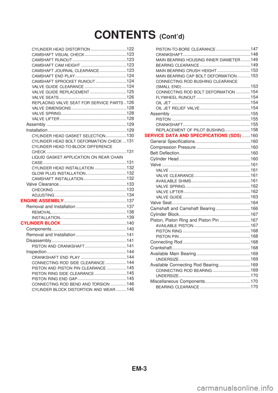
CONTENTS(Cont'd)
EM-3
Page 2149 of 2898
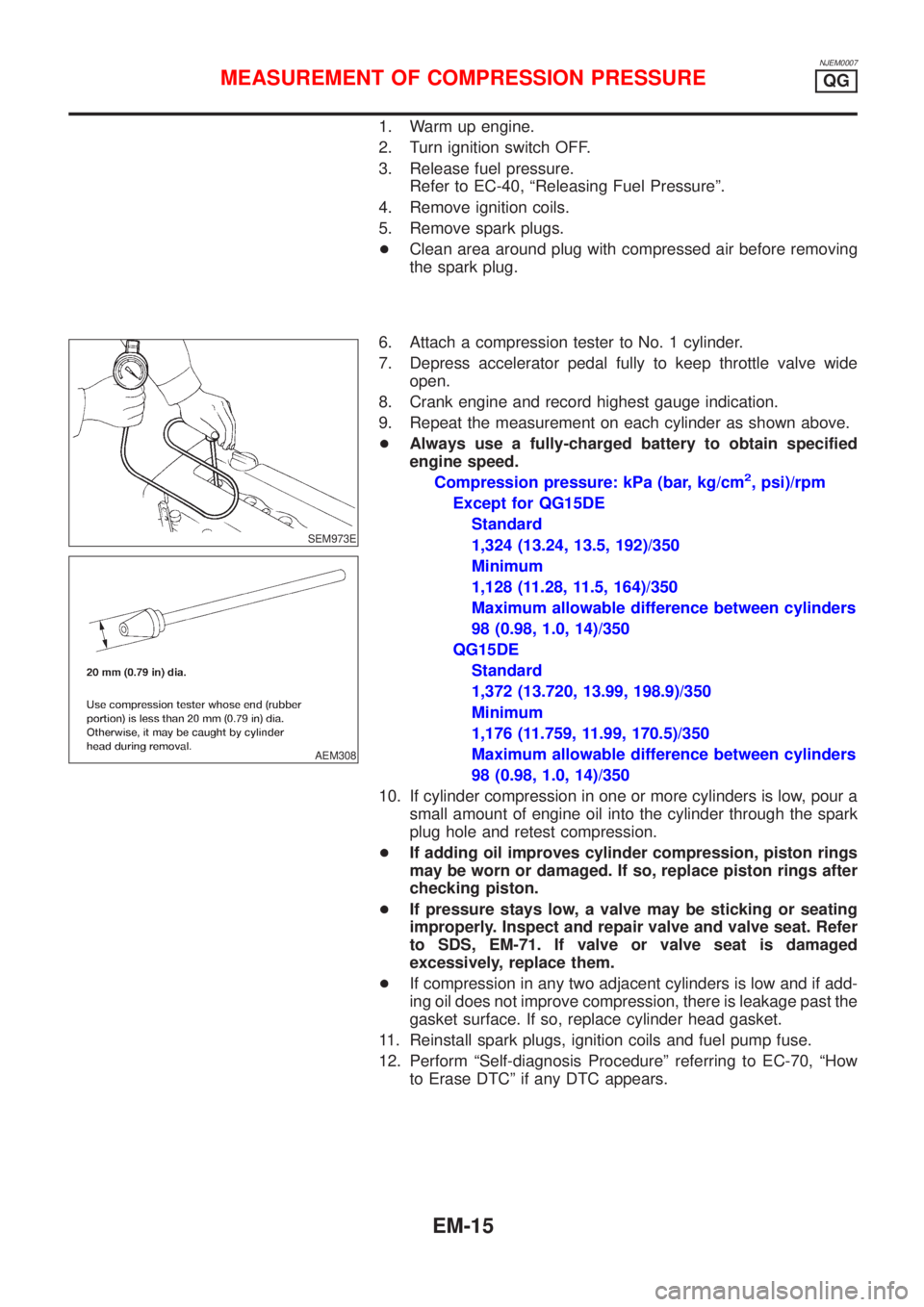
NJEM0007
1. Warm up engine.
2. Turn ignition switch OFF.
3. Release fuel pressure.
Refer to EC-40, ªReleasing Fuel Pressureº.
4. Remove ignition coils.
5. Remove spark plugs.
+Clean area around plug with compressed air before removing
the spark plug.
SEM973E
AEM308
6. Attach a compression tester to No. 1 cylinder.
7. Depress accelerator pedal fully to keep throttle valve wide
open.
8. Crank engine and record highest gauge indication.
9. Repeat the measurement on each cylinder as shown above.
+Always use a fully-charged battery to obtain specified
engine speed.
Compression pressure: kPa (bar, kg/cm
2, psi)/rpm
Except for QG15DE
Standard
1,324 (13.24, 13.5, 192)/350
Minimum
1,128 (11.28, 11.5, 164)/350
Maximum allowable difference between cylinders
98 (0.98, 1.0, 14)/350
QG15DE
Standard
1,372 (13.720, 13.99, 198.9)/350
Minimum
1,176 (11.759, 11.99, 170.5)/350
Maximum allowable difference between cylinders
98 (0.98, 1.0, 14)/350
10. If cylinder compression in one or more cylinders is low, pour a
small amount of engine oil into the cylinder through the spark
plug hole and retest compression.
+If adding oil improves cylinder compression, piston rings
may be worn or damaged. If so, replace piston rings after
checking piston.
+If pressure stays low, a valve may be sticking or seating
improperly. Inspect and repair valve and valve seat. Refer
to SDS, EM-71. If valve or valve seat is damaged
excessively, replace them.
+If compression in any two adjacent cylinders is low and if add-
ing oil does not improve compression, there is leakage past the
gasket surface. If so, replace cylinder head gasket.
11. Reinstall spark plugs, ignition coils and fuel pump fuse.
12. Perform ªSelf-diagnosis Procedureº referring to EC-70, ªHow
to Erase DTCº if any DTC appears.
MEASUREMENT OF COMPRESSION PRESSUREQG
EM-15
Page 2150 of 2898
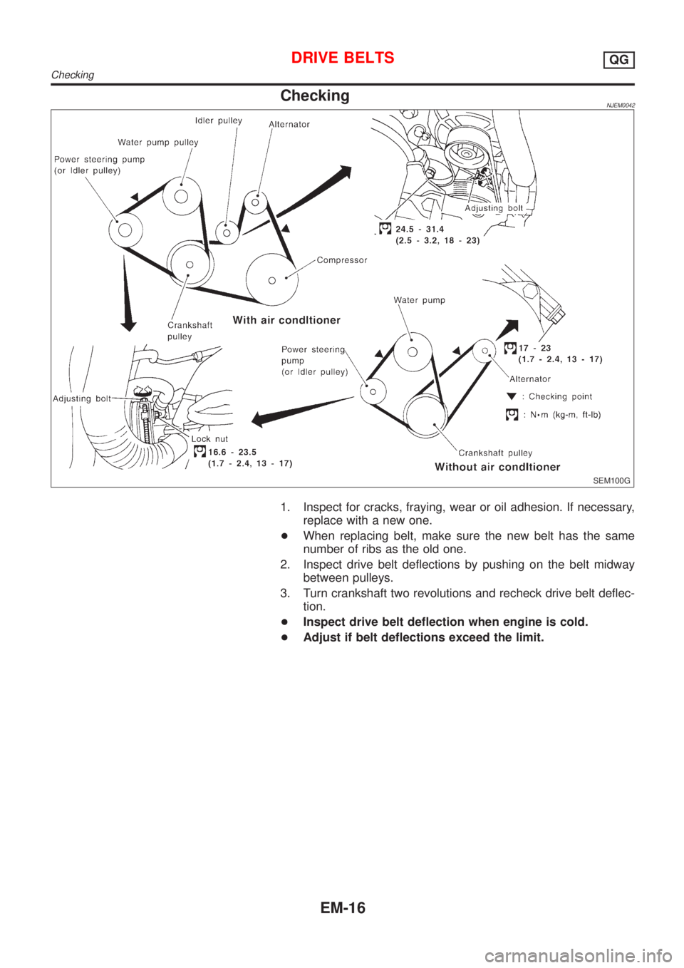
CheckingNJEM0042
SEM100G
1. Inspect for cracks, fraying, wear or oil adhesion. If necessary,
replace with a new one.
+When replacing belt, make sure the new belt has the same
number of ribs as the old one.
2. Inspect drive belt deflections by pushing on the belt midway
between pulleys.
3. Turn crankshaft two revolutions and recheck drive belt deflec-
tion.
+Inspect drive belt deflection when engine is cold.
+Adjust if belt deflections exceed the limit.
DRIVE BELTSQG
Checking
EM-16
Page 2151 of 2898
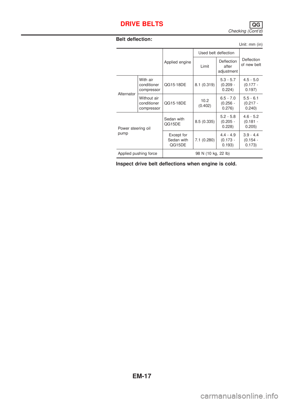
Belt deflection:
Unit: mm (in)
Applied engineUsed belt deflection
Deflection
of new belt
LimitDeflection
after
adjustment
AlternatorWith air
conditioner
compressorQG15´18DE 8.1 (0.319)5.3 - 5.7
(0.209 -
0.224)4.5 - 5.0
(0.177 -
0.197)
Without air
conditioner
compressorQG15´18DE10.2
(0.402)6.5 - 7.0
(0.256 -
0.276)5.5 - 6.1
(0.217 -
0.240)
Power steering oil
pumpSedan with
QG15DE8.5 (0.335)5.2 - 5.8
(0.205 -
0.228)4.6 - 5.2
(0.181 -
0.205)
Except for
Sedan with
QG15DE7.1 (0.280)4.4 - 4.9
(0.173 -
0.193)3.9 - 4.4
(0.154 -
0.173)
Applied pushing force 98 N (10 kg, 22 lb)
Inspect drive belt deflections when engine is cold.
DRIVE BELTSQG
Checking (Cont'd)
EM-17