2001 NISSAN ALMERA diagram
[x] Cancel search: diagramPage 3 of 2898

AUTOMATIC TRANSAXLE
SECTION
AT
CONTENTS
EURO-OBD
TROUBLE DIAGNOSIS - INDEX....................................5
Alphabetical & P No. Index for DTC ...........................5
PRECAUTIONS...............................................................7
Supplemental Restraint System (SRS)²AIR
BAG²and²SEAT BELT PRE-TENSIONER²...............7
Precautions for On Board Diagnostic (EURO-
OBD) System of A/T and Engine - Euro-OBD - ..........7
Precautions ..................................................................7
Service Notice or Precautions .....................................9
Wiring Diagrams and Trouble Diagnosis ...................10
PREPARATION............................................................. 11
Special Service Tools ................................................ 11
Commercial Service Tools .........................................13
A/T FLUID......................................................................15
Checking A/T Fluid ....................................................15
Changing A/T Fluid ....................................................15
OVERALL SYSTEM......................................................16
A/T Electrical Parts Location .....................................16
Circuit Diagram ..........................................................17
Cross-sectional View - 3AX00, 3AX01, 3AX19,
3AX63 and 3AX64 models ........................................19
Cross-sectional View - 3AX10 and 3AX18
models .......................................................................20
Hydraulic Control Circuit ............................................21
Shift Mechanism ........................................................22
Control System ..........................................................31
Control Mechanism ....................................................32
Control Valve .............................................................37
EXCEPT FOR EURO-OBD
ON BOARD DIAGNOSTIC............................................39
CONSULT-II ...............................................................39
Diagnostic Procedure Without CONSULT-II ..............44EURO-OBD
ON BOARD DIAGNOSTIC SYSTEM............................50
Introduction ................................................................50
EURO-OBD Function for A/T System .......................50
One or Two Trip Detection Logic of EURO-OBD ......50
EURO-OBD Diagnostic Trouble Code (DTC)............50
Malfunction Indicator (MI) ..........................................54
CONSULT-II ...............................................................54
Diagnostic Procedure Without CONSULT-II ..............63
EXCEPT FOR EURO-OBD
TROUBLE DIAGNOSIS -...............................................69
Introduction ................................................................69
Work Flow ..................................................................73
EURO-OBD
TROUBLE DIAGNOSIS - INTRODUCTION..................74
Introduction ................................................................74
Work Flow ..................................................................78
TROUBLE DIAGNOSIS - BASIC INSPECTION...........80
A/T Fluid Check .........................................................80
Stall Test ....................................................................80
Line Pressure Test .....................................................84
Road Test...................................................................85
TROUBLE DIAGNOSIS - GENERAL
DESCRIPTION.............................................................105
Symptom Chart ........................................................105
TCM Terminals and Reference Value...................... 118
TROUBLE DIAGNOSIS FOR POWER SUPPLY........123
Wiring Diagram - AT - MAIN ....................................123
Diagnostic Procedure ..............................................124
EXCEPT FOR EURO-OBD
VEHICLE SPEED SENSOR.A/T..................................126
Page 4 of 2898

Description ...............................................................126
Wiring Diagram - AT - VSSA/T ................................128
Diagnostic Procedure ..............................................129
VHCL SPEED SEN.MTR VEHICLE............................131
Description ...............................................................131
Wiring Diagram - AT - VSSMTR ..............................132
Diagnostic Procedure ..............................................133
THROTTLE POSITION................................................134
Description ...............................................................134
Wiring Diagram - AT - TPS ......................................136
Diagnostic Procedure ..............................................137
Component Inspection .............................................141
SHIFT SOLENOID VALVE A......................................142
Description ...............................................................142
Wiring Diagram - AT - SSV/A ..................................144
Diagnostic Procedure ..............................................145
Component Inspection .............................................147
SHIFT SOLENOID VALVE B......................................148
Description ...............................................................148
Wiring Diagram - AT - SSV/B ..................................150
Diagnostic Procedure ..............................................151
Component Inspection .............................................153
OVERRUN CLUTCH SOLENOID................................154
Description ...............................................................154
Wiring Diagram - AT - OVRCSV..............................155
Diagnostic Procedure ..............................................156
Component Inspection .............................................158
TORQUE CONVERTER CLUTCH...............................159
Description ...............................................................159
Wiring Diagram - AT - TCV......................................161
Diagnostic Procedure ..............................................162
Component Inspection .............................................164
BATT/FLUID TEMP SEN (A/T FLUID TEMP
SENSOR CIRCUIT AND TCM POWER SOURCE)....165
Description ...............................................................165
Wiring Diagram - AT - BA/FTS ................................167
Diagnostic Procedure ..............................................168
Component Inspection .............................................171
ENGINE SPEED SIGNAL............................................172
Description ...............................................................172
Wiring Diagram - AT - ENGSS ................................173
Diagnostic Procedure ..............................................174
LINE PRESSURE SOLENOID....................................176
Description ...............................................................176
Wiring Diagram - AT - LPSV....................................178
Diagnostic Procedure ..............................................179
Component Inspection .............................................182
EURO-OBD
DTC P0705 PARK/NEUTRAL POSITION (PNP)
SWITCH.......................................................................183
Description ...............................................................183Wiring Diagram - AT - PNP/SW...............................185
Diagnostic Procedure ..............................................186
Component Inspection .............................................188
DTC P0710 A/T FLUID TEMPERATURE SENSOR
CIRCUIT.......................................................................189
Description ...............................................................189
Wiring Diagram - AT - FTS ......................................191
Diagnostic Procedure ..............................................192
Component Inspection .............................................194
DTC P0720 VEHICLE SPEED SENSOR.A/T..............195
Description ...............................................................195
Wiring Diagram - AT - VSSA/T ................................197
Diagnostic Procedure ..............................................198
DTC P0725 ENGINE SPEED SIGNAL.......................200
Description ...............................................................200
Wiring Diagram - AT - ENGSS ................................201
Diagnostic Procedure ..............................................202
DTC P0731 A/T 1ST GEAR FUNCTION....................204
Description ...............................................................204
Wiring Diagram - AT - 1ST ......................................207
Diagnostic Procedure ..............................................208
Component Inspection .............................................209
DTC P0732 A/T 2ND GEAR FUNCTION.................... 211
Description ............................................................... 211
Wiring Diagram - AT - 2ND......................................214
Diagnostic Procedure ..............................................215
Component Inspection .............................................216
DTC P0733 A/T 3RD GEAR FUNCTION....................217
Description ...............................................................217
Wiring Diagram - AT - 3RD......................................220
Diagnostic Procedure ..............................................221
Component Inspection .............................................222
DTC P0734 A/T 4TH GEAR FUNCTION....................223
Description ...............................................................223
Wiring Diagram - AT - 4TH ......................................227
Diagnostic Procedure ..............................................228
Component Inspection .............................................232
DTC P0740 TORQUE CONVERTER CLUTCH
SOLENOID VALVE......................................................233
Description ...............................................................233
Wiring Diagram - AT - TCV......................................235
Diagnostic Procedure ..............................................236
Component Inspection .............................................238
DTC P0745 LINE PRESSURE SOLENOID VALVE...239
Description ...............................................................239
Wiring Diagram - AT - LPSV....................................241
Diagnostic Procedure ..............................................242
Component Inspection .............................................245
DTC P0750 SHIFT SOLENOID VALVE A..................246
Description ...............................................................246
Wiring Diagram - AT - SSV/A ..................................248
Diagnostic Procedure ..............................................249
CONTENTS(Cont'd)
AT-2
Page 5 of 2898

Component Inspection .............................................251
DTC P0755 SHIFT SOLENOID VALVE B..................252
Description ...............................................................252
Wiring Diagram - AT - SSV/B ..................................254
Diagnostic Procedure ..............................................255
Component Inspection .............................................257
DTC P1705 THROTTLE POSITION SENSOR...........258
Description ...............................................................258
Wiring Diagram - AT - TPS ......................................261
Diagnostic Procedure ..............................................263
Component Inspection .............................................267
DTC P1760 OVERRUN CLUTCH SOLENOID
VALVE..........................................................................268
Description ...............................................................268
Wiring Diagram - AT - OVRCSV..............................270
Diagnostic Procedure ..............................................271
Component Inspection .............................................273
DTC BATT/FLUID TEMP SEN (A/T FLUID TEMP
SENSOR CIRCUIT AND TCM POWER SOURCE)....274
Description ...............................................................274
Wiring Diagram - AT - BA/FTS ................................276
Diagnostic Procedure ..............................................277
Component Inspection .............................................280
DTC VHCL SPEED SEN.MTR VEHICLE SPEED
SENSOR.MTR..............................................................281
Description ...............................................................281
Wiring Diagram - AT - VSSMTR ..............................283
Diagnostic Procedure ..............................................285
DTC CONTROL UNIT (RAM), CONTROL UNIT
(ROM)...........................................................................286
Description ...............................................................286
Diagnostic Procedure ..............................................286
DTC CONTROL UNIT (EEP ROM).............................288
Description ...............................................................288
Diagnostic Procedure ..............................................289
TROUBLE DIAGNOSES FOR SYMPTOMS...............290
Wiring Diagram - AT - NONDTC/General and
Except for Euro-OBD ...............................................290
Wiring Diagram - AT - NONDTC/EURO-OBD .........292
1. O/D OFF Indicator Lamp Does Not Come On....296
2. Engine Cannot Be Started In²P²and²N²
Position ....................................................................299
3. In²P²Position, Vehicle Moves Forward Or
Backward When Pushed .........................................300
4. In²N²Position, Vehicle Moves ...........................301
5. Large Shock.²N²->²R²Position .......................303
6. Vehicle Does Not Creep Backward In²R²
Position ....................................................................305
7. Vehicle Does Not Creep Forward In²D²,²2²
Or²1²Position .........................................................3088. Vehicle Cannot Be Started From D
1................... 311
9. A/T Does Not Shift: D
1-> D2Or Does Not
Kickdown: D
4-> D2..................................................314
10. A/T Does Not Shift: D
2-> D3.............................317
11. A/T Does Not Shift: D
3-> D4.............................320
12. A/T Does Not Perform Lock-up .........................323
13. A/T Does Not Hold Lock-up Condition ..............325
14. Lock-up Is Not Released ...................................327
15. Engine Speed Does Not Return To Idle (Light
Braking D
4-> D3).....................................................328
16. Vehicle Does Not Start From D
1.......................330
17. A/T Does Not Shift: D
4-> D3, When
Overdrive Control Switch²ON²->²OFF²...............331
18. A/T Does Not Shift: D
3-> 22, When Selector
Lever²D²->²2²Position.........................................332
19. A/T Does Not Shift: 2
2-> 11, When Selector
Lever²2²->²1²Position .........................................333
20. Vehicle Does Not Decelerate By Engine
Brake........................................................................334
21. TCM Self-diagnosis Does Not Activate (PNP,
Overdrive Control and Throttle Position Switches
Circuit Checks) ........................................................334
A/T SHIFT LOCK SYSTEM.........................................343
Description ...............................................................343
Shift Lock System Electrical Parts Location............343
Wiring Diagram - SHIFT -........................................344
Diagnostic Procedure ..............................................345
KEY INTERLOCK CABLE..........................................349
Components.............................................................349
Removal ...................................................................349
Installation ................................................................350
ON-VEHICLE SERVICE..............................................351
Control Valve Assembly and Accumulators .............351
Control Cable Adjustment ........................................352
Park/Neutral Position (PNP) Switch Adjustment .....352
Differential Side Oil Seal Replacement ...................353
Revolution Sensor Replacement .............................353
REMOVAL AND INSTALLATION...............................354
Removal ...................................................................354
Installation ................................................................355
OVERHAUL.................................................................357
Components-1 3AX00, 3AX01, 3AX19, 3AX63
and 3AX64 models ..................................................357
Components-1 3AX10 and 3AX18 models .............358
Components-2 3AX00, 3AX01, 3AX19, 3AX63
and 3AX64 models ..................................................359
Components-2 3AX10 and 3AX18 models .............360
Components-3 3AX00, 3AX01, 3AX19, 3AX63
and 3AX64 models ..................................................361
Components-3 3AX10 and 3AX18 models .............362
Oil Channel ..............................................................363
CONTENTS(Cont'd)
AT-3
Page 12 of 2898

The torque converter should not be replaced if:
+The fluid has an odor, is discolored, and there is no evidence of metal or clutch facing particles.
+The threads in one or more of the converter bolt holes are damaged.
+Transaxle failure did not display evidence of damaged or worn internal parts, steel particles or clutch plate
lining material in unit and inside the fluid filter.
+Vehicle has been exposed to high mileage (only). The exception may be where the torque converter clutch
dampener plate lining has seen excess wear by vehicles operated in heavy and/or constant traffic, such
as taxi, delivery or police use.
EURO-OBD SELF-DIAGNOSIS Ð EURO-OBD ÐNJAT0247S04+A/T self-diagnosis is performed by the TCM in combination with the ECM. The results can be read through
the blinking pattern of the O/D OFF indicator or the malfunction indicator (MI). Refer to the table on AT-55
for the indicator used to display each self-diagnostic result.
+The self-diagnostic results indicated by the MI are automatically stored in both the ECM and TCM memo-
ries.
Always perform the procedure ªHOW TO ERASE DTCº on AT-52 to complete the repair and avoid
unnecessary blinking of the MI.
+The following self-diagnostic items can be detected using ECM self-diagnostic results mode* only when
the O/D OFF indicator lamp does not indicate any malfunctions.
þ PNP switch
þ A/T 1st, 2nd, 3rd, or 4th gear function
*: For details of EURO-OBD, refer to EC-59, ªON BOARD DIAGNOSTIC SYSTEM DESCRIPTIONº.
+Certain systems and components, especially those related to EURO-OBD, may use a new style
slide-locking type harness connector.
For description and how to disconnect, refer to EL-6, ªHARNESS CONNECTORº.
Wiring Diagrams and Trouble DiagnosisNJAT0248When you read wiring diagrams, refer to the following:
+GI-11, ªHOW TO READ WIRING DIAGRAMSº
+EL-10, ªPOWER SUPPLY ROUTINGº
When you perform trouble diagnosis, refer to the following:
+GI-32, ªHOW TO FOLLOW TEST GROUP IN TROUBLE DIAGNOSISº
+GI-21, ªHOW TO PERFORM EFFICIENT DIAGNOSIS FOR AN ELECTRICAL INCIDENTº
PRECAUTIONS
Service Notice or Precautions (Cont'd)
AT-10
Page 19 of 2898

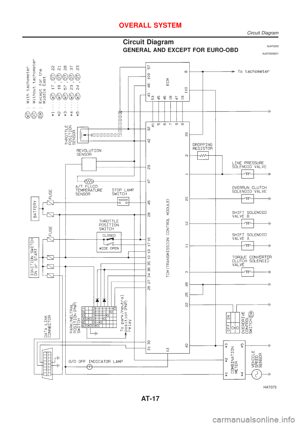
Circuit DiagramNJAT0009GENERAL AND EXCEPT FOR EURO-OBDNJAT0009S01
HAT073
OVERALL SYSTEM
Circuit Diagram
AT-17
Page 20 of 2898

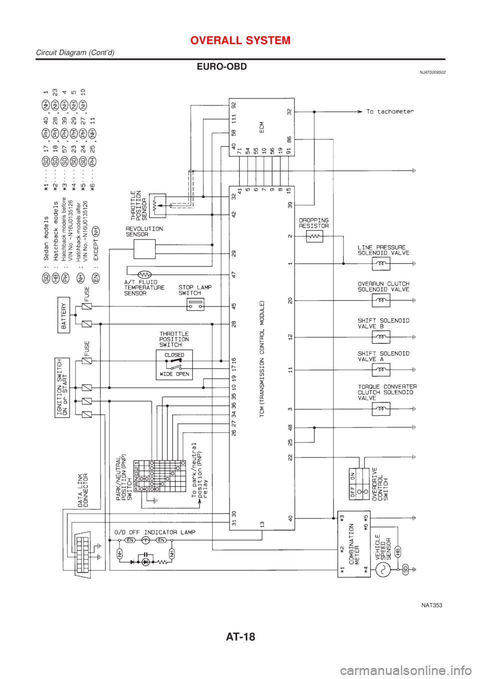
EURO-OBDNJAT0009S02
NAT353
OVERALL SYSTEM
Circuit Diagram (Cont'd)
AT-18
Page 125 of 2898

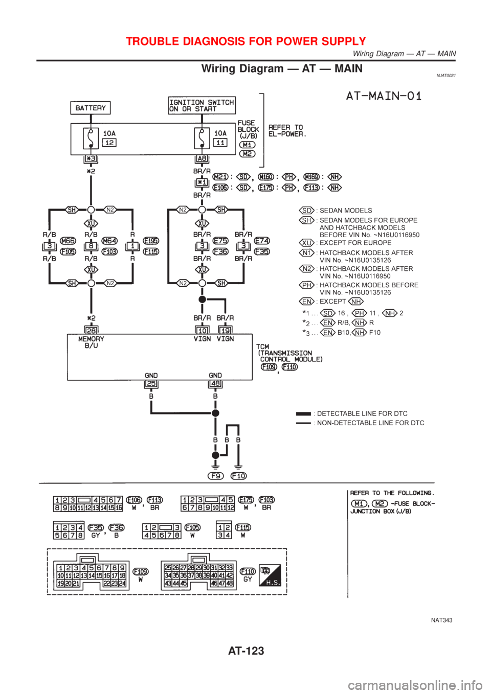
Wiring Diagram Ð AT Ð MAINNJAT0031
NAT343
TROUBLE DIAGNOSIS FOR POWER SUPPLY
Wiring Diagram Ð AT Ð MAIN
AT-123
Page 126 of 2898

TCM TERMINALS AND REFERENCE VALUENJAT0031S01Remarks: Specification data are reference values.
Terminal
No.Wire color Item ConditionJudgement stan-
dard
10 BR/R Power source
When turning ignition switch to
ªONº.Battery voltage
When turning ignition switch to
ªOFFº.1V or less
19 BR/R Power source Same as No. 10
25 B Ground Ð Ð
28 R/BPower source
(Memory back-up)
or
When turning ignition switch to
ªOFFº.Battery voltage
When turning ignition switch to
ªONº.Battery voltage
48 B Ground
ÐÐ
Diagnostic ProcedureNJAT0231
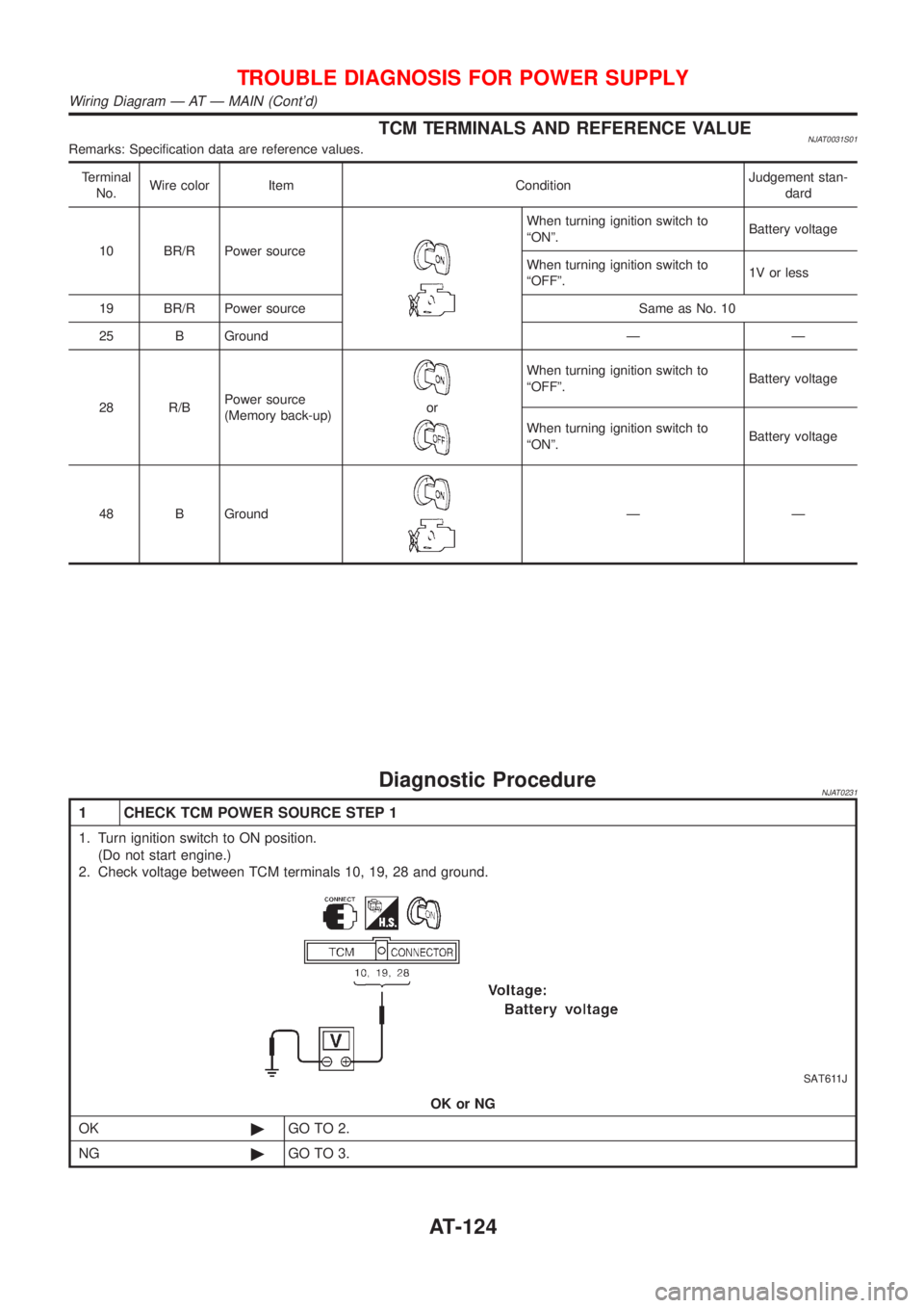
1 CHECK TCM POWER SOURCE STEP 1
1. Turn ignition switch to ON position.
(Do not start engine.)
2. Check voltage between TCM terminals 10, 19, 28 and ground.
SAT611J
OK or NG
OK©GO TO 2.
NG©GO TO 3.
TROUBLE DIAGNOSIS FOR POWER SUPPLY
Wiring Diagram Ð AT Ð MAIN (Cont'd)
AT-124