Page 353 of 2898
SAT992C
Control Valve Assembly and AccumulatorsNJAT0110REMOVALNJAT0110S011. Drain ATF from transaxle.
2. Remove oil pan and gasket.
SAT064K
3. Disconnect A/T solenoid valve harness connector.
AAT265A
4. Remove stopper ring from A/T solenoid harness terminal body.
5. Remove A/T solenoid harness by pushing terminal body into
transmission case.
AAT260A
6. Remove control valve assembly by removing fixing bolts.
Bolt length, number and location:
Bolt symbol A B C
Bolt length ª!º
40.0 mm
(1.575 in)33.0 mm
(1.299 in)43.5 mm
(1.713 in)
Number of bolts 5 6 2
+Be careful not to drop manual valve and servo release
accumulator return springs.
7. Disassemble and inspect control valve assembly if necessary.
Refer to AT-366.
ON-VEHICLE SERVICE
Control Valve Assembly and Accumulators
AT-351
Page 356 of 2898

SAT065K
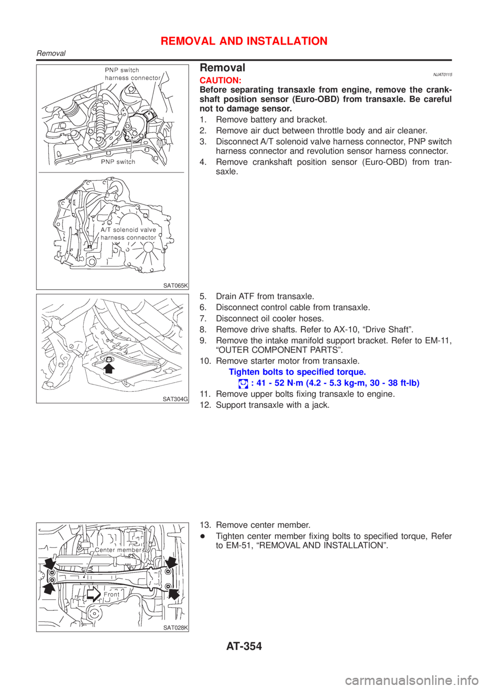
RemovalNJAT0115CAUTION:
Before separating transaxle from engine, remove the crank-
shaft position sensor (Euro-OBD) from transaxle. Be careful
not to damage sensor.
1. Remove battery and bracket.
2. Remove air duct between throttle body and air cleaner.
3. Disconnect A/T solenoid valve harness connector, PNP switch
harness connector and revolution sensor harness connector.
4. Remove crankshaft position sensor (Euro-OBD) from tran-
saxle.
SAT304G
5. Drain ATF from transaxle.
6. Disconnect control cable from transaxle.
7. Disconnect oil cooler hoses.
8. Remove drive shafts. Refer to AX-10, ªDrive Shaftº.
9. Remove the intake manifold support bracket. Refer to EM-11,
ªOUTER COMPONENT PARTSº.
10. Remove starter motor from transaxle.
Tighten bolts to specified torque.
: 41 - 52 N´m (4.2 - 5.3 kg-m, 30 - 38 ft-lb)
11. Remove upper bolts fixing transaxle to engine.
12. Support transaxle with a jack.
SAT028K
13. Remove center member.
+Tighten center member fixing bolts to specified torque, Refer
to EM-51, ªREMOVAL AND INSTALLATIONº.
REMOVAL AND INSTALLATION
Removal
AT-354
Page 469 of 2898
AAT261A
b. Pass solenoid harness through transmission case and install
terminal body on transmission case by pushing it.
c. Install stopper ring to terminal body.
AAT260A
d. Tighten boltsA,BandC.
:7-9N´m(0.7 - 0.9 kg-m, 61 - 78 in-lb)
Bolt length, number and location
Bolt symbolABC
Bolt length ª!º
40.0 mm
(1.575 in)33.0 mm
(1.299 in)43.5 mm
(1.713 in)
Number of bolts 5 6 2
SAT418D
8. Install oil pan.
a. Attach magnet to oil pan.
SAT128E
b. Install new oil pan gasket on transmission case.
c. Install oil pan on transmission case.
+Always replace oil pan bolts as they are self-sealing bolts.
+Tighten the four bolts in a criss-cross pattern to prevent
dislocation of gasket.
d. Tighten drain plug to specified torque.
ASSEMBLY
Assembly (4) (Cont'd)
AT-467
Page 470 of 2898
SAT023JB
9. Install PNP switch.
a. Set manual shaft in ªPº position.
b. Temporarily install PNP switch on manual shaft.
c. Move selector lever to ªNº position.
SAT426DB
d. Usea4mm(0.157 in) pin for this adjustment.
1) Insert the pin straight into the manual shaft adjustment hole.
2) Rotate PNP switch until the pin can also be inserted straight
into hole in PNP switch.
e. Tighten PNP switch fixing bolts.
f. Remove pin from adjustment hole after adjusting PNP switch.
SAT586H
10. Install oil charging pipe and oil cooler tube to transmission
case.
SAT428DA
11. Install torque converter.
a. Pour ATF into torque converter.
+Approximately 1 liter (7/8 Imp qt) of fluid is required for a
new torque converter.
+When reusing old torque converter, add the same amount
of fluid as was drained.
SAT429D
b. Install torque converter while aligning notches of torque con-
verter with notches of oil pump.
ASSEMBLY
Assembly (4) (Cont'd)
AT-468
Page 527 of 2898
2. Cover openings to prevent entrance of air and dirt whenever
disconnecting brake line.
InspectionNJBR0012Check brake lines (tubes and hoses) for cracks, deterioration or
other damage. Replace any damaged parts.
SBR686C
InstallationNJBR0013CAUTION:
+Refill with new brake fluid ªDOT 3 or DOT 4º.
+Never reuse drained brake fluid.
1. Tighten all flare nuts and connecting bolts.
Specification:
Flare nut
15 - 18 N´m (1.5 - 1.8 kg-m, 11 - 13 ft-lb)
Connecting bolt
17 - 20 N´m (1.7 - 2.0 kg-m, 12 - 14 ft-lb)
2. Refill until new brake fluid comes out of each air bleeder valve.
3. Bleed air. Refer to ªBleeding Brake Systemº, BR-9.
BRAKE HYDRAULIC LINE
Inspection
BR-11
Page 537 of 2898
InstallationNJBR0026CAUTION:
+Be careful not to deform or bend brake pipes, during
installation of booster.
+Replace clevis pin if damaged.
+Refill with new brake fluid ªDOT 3 or DOT 4º.
+Never reuse drained brake fluid.
+Take care not to damage brake booster mounting bolt
thread when installing. Due to the acute angle of
installation, the threads can be damaged with the dash
panel.
SBR237EA
1. Before fitting booster, temporarily adjust clevis to dimension
shown.
2. Fit booster, then secure mounting nuts (brake pedal bracket to
master cylinder) lightly.
3. Connect brake pedal and booster input rod with clevis pin.
4. Secure mounting nuts.
Specification:
13 - 16 N´m (1.3 - 1.6 kg-m,9-12ft-lb)
5. Install master cylinder. Refer to ªInstallationº in ªMASTER
CYLINDERº, BR-16, 19.
6. Bleed air. Refer to ªBleeding Brake Systemº, BR-9.
BRAKE BOOSTER
Installation
BR-21
Page 546 of 2898
SBR574
AssemblyNJBR00341. Insert piston seal into groove on cylinder body.
2. With piston boot fitted to piston, insert piston boot into groove
on cylinder body and install piston.
3. Properly secure piston boot.
SBR980B
InstallationNJBR0035CAUTION:
+Refill with new brake fluid ªDOT 3 or DOT 4º.
+Never reuse drained brake fluid.
1. Install brake hose to caliper securely.
2. Install all parts and secure all bolts.
3. Bleed air. Refer to ªBleeding Brake Systemº, BR-9.
FRONT DISC BRAKE
Assembly
BR-30
Page 558 of 2898
SBR307E
InstallationNJBR0043CAUTION:
+Refill with new brake fluid ªDOT 4º.
+Never reuse drained brake fluid.
1. Install caliper assembly.
+As shown in the figure, align the piston's concave to the pad's
convex, then install the cylinder body to the torque member.
2. Install brake hose to caliper securely.
3. Install all parts and secure all bolts.
4. Bleed air. Refer to ªBleeding Brake Systemº, BR-9.
REAR DISC BRAKE (CAM & STRUT TYPE)
Installation
BR-42