2001 NISSAN ALMERA gas type
[x] Cancel search: gas typePage 520 of 2898

Supplemental Restraint System (SRS) ªAIR
BAGº and ªSEAT BELT PRE-TENSIONERº
NJBR0139The Supplemental Restraint System such as ªAIR BAGº and ªSEAT BELT PRE-TENSIONERº used along with
a seat belt, helps to reduce the risk or severity of injury to the driver and front passenger for certain types of
collision. The SRS system composition which is available to NISSAN MODEL N16 is as follows (The compo-
sition varies according to the destination and optional equipment.):
+For a frontal collision
The Supplemental Restraint System consists of driver air bag module (located in the center of the steer-
ing wheel), front passenger air bag module (located on the instrument panel on passenger side), front seat
belt pre-tensioners, a diagnosis sensor unit, warning lamp, wiring harness and spiral cable.
+For a side collision
The Supplemental Restraint System consists of front side air bag module (located in the outer side of front
seat), side air bag (satellite) sensor, diagnosis sensor unit (one of components of air bags for a frontal
collision), wiring harness, warning lamp (one of components of air bags for a frontal collision).
Information necessary to service the system safely is included in theRS sectionof this Service Manual.
WARNING:
+To avoid rendering the SRS inoperative, which could increase the risk of personal injury or death
in the event of a collision which would result in air bag inflation, all maintenance should be per-
formed by an authorized NISSAN dealer.
+Improper maintenance, including incorrect removal and installation of the SRS, can lead to per-
sonal injury caused by unintentional activation of the system. For removal of Spiral Cable and Air
Bag Module, see the RS section.
+Do not use electrical test equipment on any circuit related to the SRS unless instructed to in this
Service Manual. SRS wiring harnesses can be identified by yellow harness connector.
SBR686C
Precautions for Brake SystemNJBR0002+Recommended fluid is brake fluid ªDOT 4º.
+Never reuse drained brake fluid.
+Be careful not to splash brake fluid on painted areas.
+To clean or wash all parts of master cylinder, disc brake
caliper and wheel cylinder, use clean brake fluid.
+Never use mineral oils such as gasoline or kerosene. They
will ruin rubber parts of the hydraulic system.
+Use flare nut wrench when removing and installing brake
tube.
+Always torque brake lines when installing.
+Burnish the brake contact surfaces after refinishing or
replacing drums or rotors, after replacing pads or linings,
or if a soft pedal occurs at very low mileage.
Refer to ªBrake Burnishing Procedureº, ªON-VEHICLE
SERVICEº, BR-8.
WARNING:
+Clean brake pads and shoes with a waste cloth, then wipe
with a dust collector.
PRECAUTIONS
Supplemental Restraint System (SRS) ªAIR BAGº and ªSEAT BELT PRE-TENSIONERº
BR-4
Page 616 of 2898
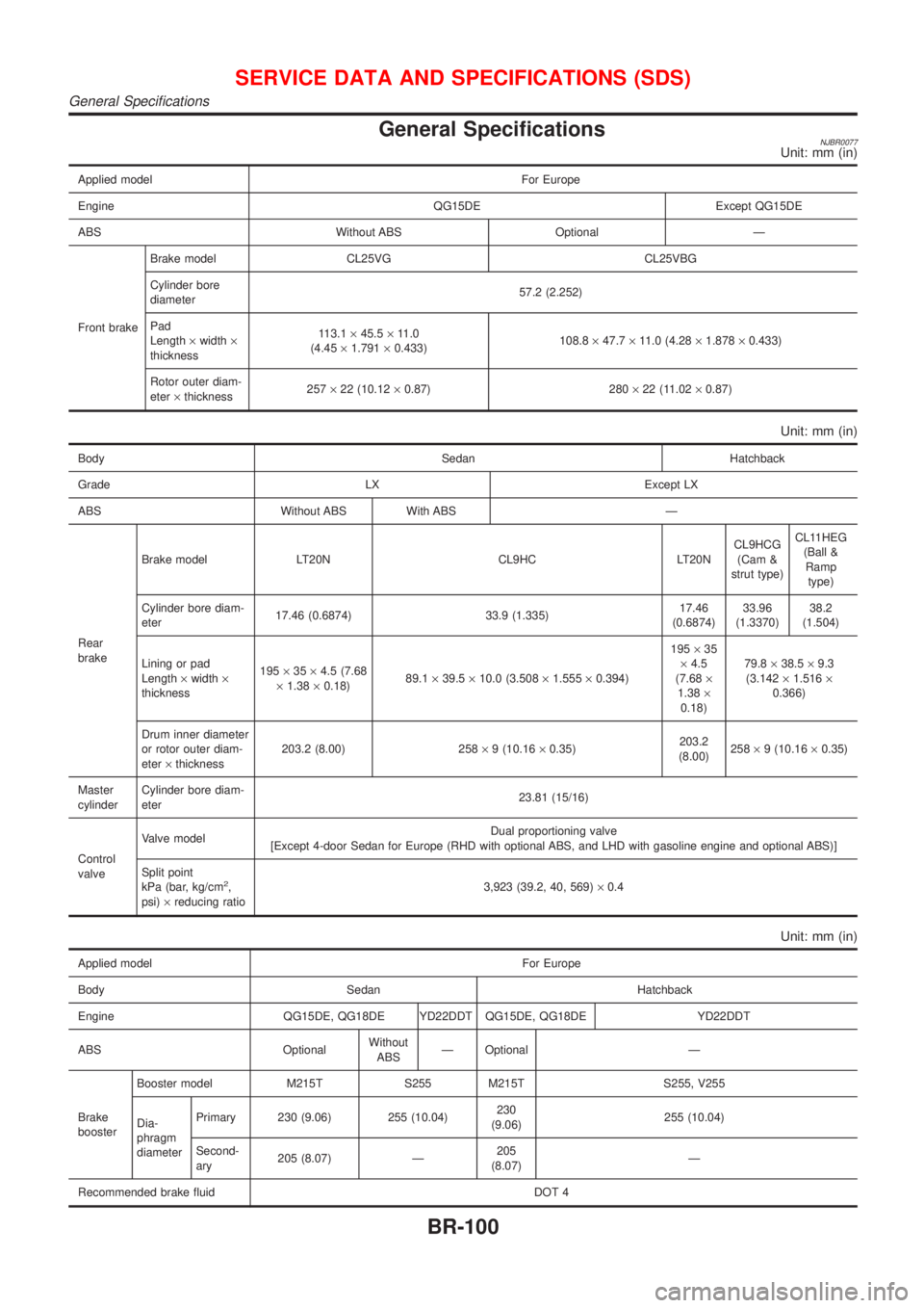
General SpecificationsNJBR0077Unit: mm (in)
Applied model For Europe
Engine QG15DE Except QG15DE
ABS Without ABS Optional Ð
Front brakeBrake model CL25VG CL25VBG
Cylinder bore
diameter57.2 (2.252)
Pad
Length´width´
thickness113.1´45.5´11.0
(4.45´1.791´0.433)108.8´47.7´11.0 (4.28´1.878´0.433)
Rotor outer diam-
eter´thickness257´22 (10.12´0.87) 280´22 (11.02´0.87)
Unit: mm (in)
Body Sedan Hatchback
Grade LX Except LX
ABS Without ABS With ABS Ð
Rear
brakeBrake model LT20N CL9HC LT20NCL9HCG
(Cam &
strut type)CL11HEG
(Ball &
Ramp
type)
Cylinder bore diam-
eter17.46 (0.6874) 33.9 (1.335)17.46
(0.6874)33.96
(1.3370)38.2
(1.504)
Lining or pad
Length´width´
thickness195´35´4.5 (7.68
´1.38´0.18)89.1´39.5´10.0 (3.508´1.555´0.394)195´35
´4.5
(7.68´
1.38´
0.18)79.8´38.5´9.3
(3.142´1.516´
0.366)
Drum inner diameter
or rotor outer diam-
eter´thickness203.2 (8.00) 258´9 (10.16´0.35)203.2
(8.00)258´9 (10.16´0.35)
Master
cylinderCylinder bore diam-
eter23.81 (15/16)
Control
valveValve modelDual proportioning valve
[Except 4-door Sedan for Europe (RHD with optional ABS, and LHD with gasoline engine and optional ABS)]
Split point
kPa (bar, kg/cm
2,
psi)´reducing ratio3,923 (39.2, 40, 569)´0.4
Unit: mm (in)
Applied model For Europe
Body Sedan Hatchback
Engine QG15DE, QG18DE YD22DDT QG15DE, QG18DE YD22DDT
ABS OptionalWithout
ABSÐ Optional Ð
Brake
boosterBooster model M215T S255 M215T S255, V255
Dia-
phragm
diameterPrimary 230 (9.06) 255 (10.04)230
(9.06)255 (10.04)
Second-
ary205 (8.07) Ð205
(8.07)Ð
Recommended brake fluid DOT 4
SERVICE DATA AND SPECIFICATIONS (SDS)
General Specifications
BR-100
Page 1045 of 2898
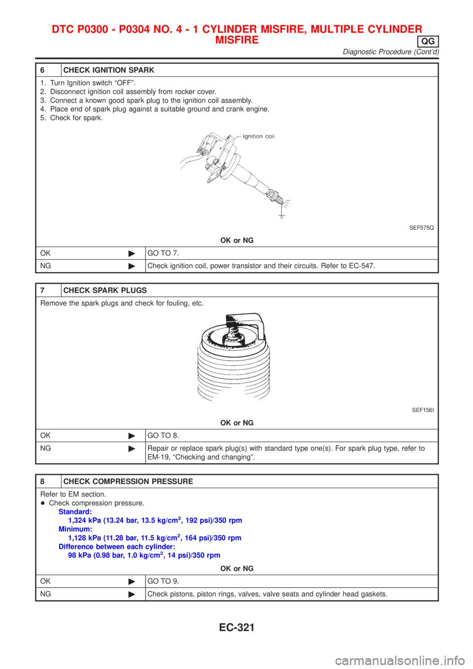
6 CHECK IGNITION SPARK
1. Turn Ignition switch ªOFFº.
2. Disconnect ignition coil assembly from rocker cover.
3. Connect a known good spark plug to the ignition coil assembly.
4. Place end of spark plug against a suitable ground and crank engine.
5. Check for spark.
SEF575Q
OK or NG
OK©GO TO 7.
NG©Check ignition coil, power transistor and their circuits. Refer to EC-547.
7 CHECK SPARK PLUGS
Remove the spark plugs and check for fouling, etc.
SEF156I
OK or NG
OK©GO TO 8.
NG©Repair or replace spark plug(s) with standard type one(s). For spark plug type, refer to
EM-19, ªChecking and changingº.
8 CHECK COMPRESSION PRESSURE
Refer to EM section.
+Check compression pressure.
Standard:
1,324 kPa (13.24 bar, 13.5 kg/cm
2, 192 psi)/350 rpm
Minimum:
1,128 kPa (11.28 bar, 11.5 kg/cm
2, 164 psi)/350 rpm
Difference between each cylinder:
98 kPa (0.98 bar, 1.0 kg/cm
2, 14 psi)/350 rpm
OK or NG
OK©GO TO 9.
NG©Check pistons, piston rings, valves, valve seats and cylinder head gaskets.
DTC P0300 - P0304 NO.4-1CYLINDER MISFIRE, MULTIPLE CYLINDER
MISFIRE
QG
Diagnostic Procedure (Cont'd)
EC-321
Page 1752 of 2898
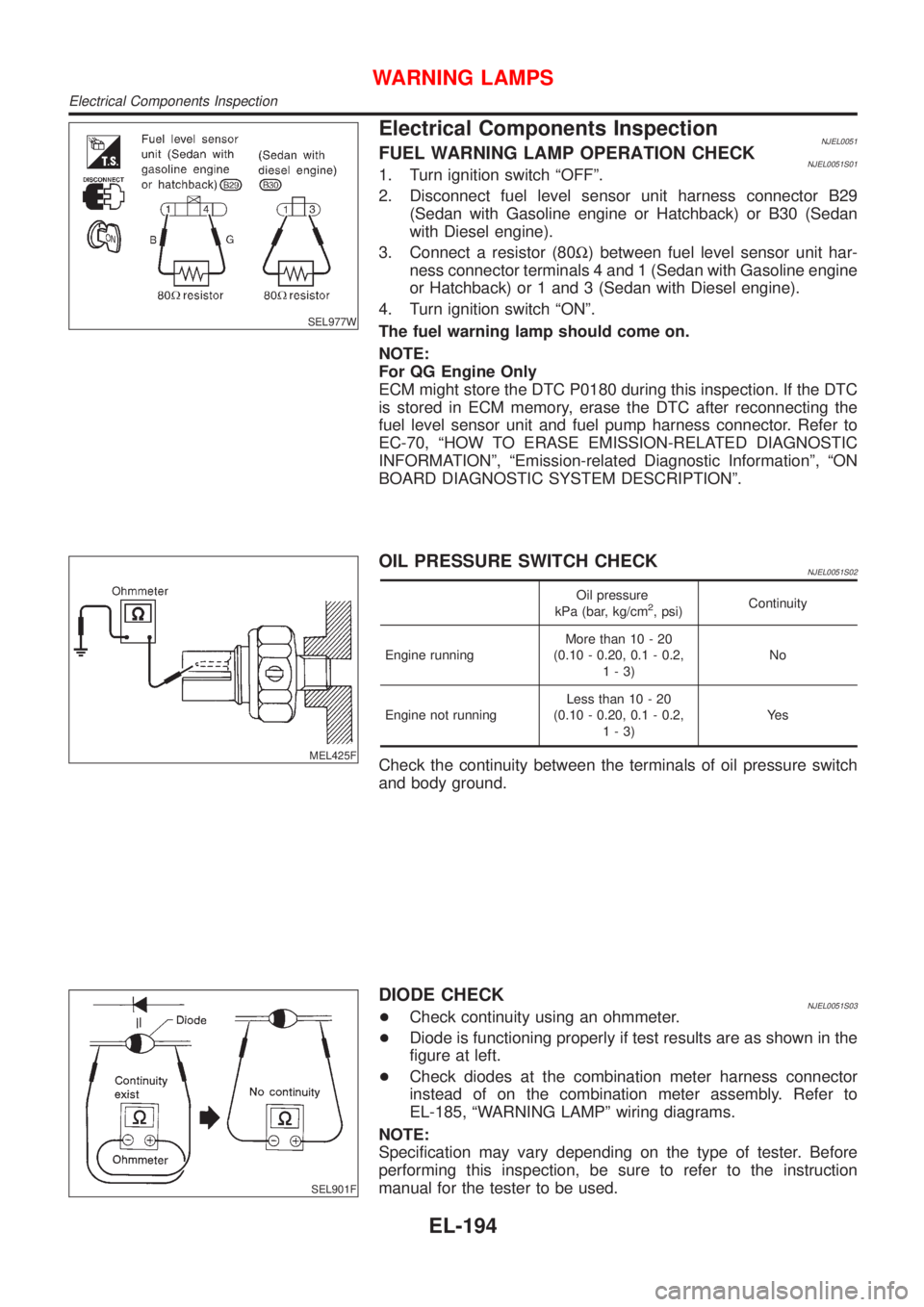
SEL977W
Electrical Components InspectionNJEL0051FUEL WARNING LAMP OPERATION CHECKNJEL0051S011. Turn ignition switch ªOFFº.
2. Disconnect fuel level sensor unit harness connector B29
(Sedan with Gasoline engine or Hatchback) or B30 (Sedan
with Diesel engine).
3. Connect a resistor (80W) between fuel level sensor unit har-
ness connector terminals 4 and 1 (Sedan with Gasoline engine
or Hatchback) or 1 and 3 (Sedan with Diesel engine).
4. Turn ignition switch ªONº.
The fuel warning lamp should come on.
NOTE:
For QG Engine Only
ECM might store the DTC P0180 during this inspection. If the DTC
is stored in ECM memory, erase the DTC after reconnecting the
fuel level sensor unit and fuel pump harness connector. Refer to
EC-70, ªHOW TO ERASE EMISSION-RELATED DIAGNOSTIC
INFORMATIONº, ªEmission-related Diagnostic Informationº, ªON
BOARD DIAGNOSTIC SYSTEM DESCRIPTIONº.
MEL425F
OIL PRESSURE SWITCH CHECKNJEL0051S02
Oil pressure
kPa (bar, kg/cm2, psi)Continuity
Engine runningMore than 10 - 20
(0.10 - 0.20, 0.1 - 0.2,
1-3)No
Engine not runningLess than 10 - 20
(0.10 - 0.20, 0.1 - 0.2,
1-3)Ye s
Check the continuity between the terminals of oil pressure switch
and body ground.
SEL901F
DIODE CHECKNJEL0051S03+Check continuity using an ohmmeter.
+Diode is functioning properly if test results are as shown in the
figure at left.
+Check diodes at the combination meter harness connector
instead of on the combination meter assembly. Refer to
EL-185, ªWARNING LAMPº wiring diagrams.
NOTE:
Specification may vary depending on the type of tester. Before
performing this inspection, be sure to refer to the instruction
manual for the tester to be used.
WARNING LAMPS
Electrical Components Inspection
EL-194
Page 2135 of 2898
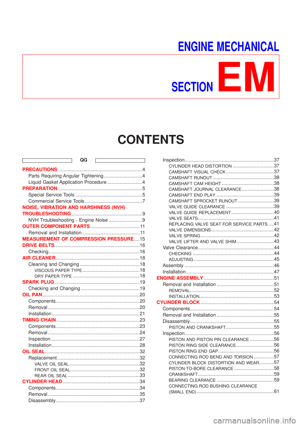
ENGINE MECHANICAL
SECTION
EM
CONTENTS
QG
PRECAUTIONS...............................................................4
Parts Requiring Angular Tightening .............................4
Liquid Gasket Application Procedure ..........................4
PREPARATION...............................................................5
Special Service Tools ..................................................5
Commercial Service Tools ...........................................7
NOISE, VIBRATION AND HARSHNESS (NVH)
TROUBLESHOOTING.....................................................9
NVH Troubleshooting - Engine Noise .........................9
OUTER COMPONENT PARTS..................................... 11
Removal and Installation ........................................... 11
MEASUREMENT OF COMPRESSION PRESSURE....15
DRIVE BELTS................................................................16
Checking ....................................................................16
AIR CLEANER...............................................................18
Cleaning and Changing .............................................18
VISCOUS PAPER TYPE...........................................18
DRY PAPER TYPE..................................................18
SPARK PLUG................................................................19
Checking and Changing ............................................19
OIL PAN.........................................................................20
Components...............................................................20
Removal .....................................................................20
Installation ..................................................................21
TIMING CHAIN..............................................................23
Components...............................................................23
Removal .....................................................................24
Inspection...................................................................27
Installation ..................................................................28
OIL SEAL.......................................................................32
Replacement ..............................................................32
VALVE OIL SEAL.....................................................32
FRONT OIL SEAL....................................................32
REAR OIL SEAL......................................................33
CYLINDER HEAD..........................................................34
Components...............................................................34
Removal .....................................................................35
Disassembly...............................................................37Inspection...................................................................37
CYLINDER HEAD DISTORTION...............................37
CAMSHAFT VISUAL CHECK....................................37
CAMSHAFT RUNOUT..............................................38
CAMSHAFT CAM HEIGHT.......................................38
CAMSHAFT JOURNAL CLEARANCE........................38
CAMSHAFT END PLAY............................................39
CAMSHAFT SPROCKET RUNOUT...........................39
VALVE GUIDE CLEARANCE....................................39
VALVE GUIDE REPLACEMENT................................40
VALVE SEATS.........................................................41
REPLACING VALVE SEAT FOR SERVICE PARTS....41
VALVE DIMENSIONS...............................................42
VALVE SPRING.......................................................42
VALVE LIFTER AND VALVE SHIM............................43
Valve Clearance.........................................................44
CHECKING.............................................................44
ADJUSTING............................................................45
Assembly ...................................................................46
Installation ..................................................................47
ENGINE ASSEMBLY.....................................................51
Removal and Installation ...........................................51
REMOVAL...............................................................52
INSTALLATION........................................................53
CYLINDER BLOCK.......................................................54
Components...............................................................54
Removal and Installation ...........................................55
Disassembly...............................................................55
PISTON AND CRANKSHAFT....................................55
Inspection...................................................................56
PISTON AND PISTON PIN CLEARANCE..................56
PISTON RING SIDE CLEARANCE............................56
PISTON RING END GAP..........................................56
CONNECTING ROD BEND AND TORSION...............57
CYLINDER BLOCK DISTORTION AND WEAR...........57
PISTON-TO-BORE CLEARANCE..............................58
CRANKSHAFT.........................................................59
BEARING CLEARANCE...........................................59
CONNECTING ROD BUSHING CLEARANCE
(SMALL END)
..........................................................61
Page 2136 of 2898
REPLACEMENT OF CONNECTING ROD
BUSHING (SMALL END)
..........................................62
FLYWHEEL/DRIVE PLATE RUNOUT........................62
Assembly ...................................................................62
PISTON..................................................................62
CRANKSHAFT.........................................................63
SERVICE DATA AND SPECIFICATIONS (SDS).........66
General Specifications ...............................................66
Compression Pressure ..............................................66
Belt Deflection............................................................67
Spark Plug .................................................................67
Cylinder Head ............................................................67
Valve ..........................................................................68
VALVE....................................................................68
VALVE SPRING.......................................................68
VALVE LIFTER........................................................68
VALVE CLEARANCE................................................69
VALVE GUIDE.........................................................69
AVAILABLE SHIMS..................................................69
VALVE SEAT...........................................................71
VALVE SEAT RESURFACE LIMIT.............................72
Camshaft and Camshaft Bearing ..............................72
Cylinder Block ............................................................73
Piston, Piston Ring and Piston Pin ...........................74
PISTON..................................................................74
PISTON RING.........................................................74
PISTON PIN............................................................74
Connecting Rod .........................................................75
Crankshaft..................................................................75
Main Bearing..............................................................75
STANDARD.............................................................75
UNDERSIZE............................................................75
Connecting Rod Bearing ...........................................76
STANDARD SIZE....................................................76
UNDERSIZE............................................................76
Bearing Clearance .....................................................76
Miscellaneous Components.......................................76
YD
PRECAUTIONS.............................................................77
Parts Requiring Angular Tightening ...........................77
Liquid Gasket Application Procedure ........................77
PREPARATION.............................................................78
Special Service Tools ................................................78
Commercial Service Tools .........................................80
NOISE, VIBRATION AND HARSHNESS (NVH)
TROUBLESHOOTING...................................................82
NVH Troubleshooting - Engine Noise .......................82
MEASUREMENT OF COMPRESSION PRESSURE....83
DRIVE BELTS................................................................85
Inspection...................................................................85
Adjustment .................................................................85
AIR CONDITIONER COMPRESSOR BELT................86
ALTERNATOR & WATER PUMP BELT.....................86
Removal .....................................................................86
Installation ..................................................................87
AIR CLEANER...............................................................88
Changing Air Cleaner Filter .......................................88
VISCOUS PAPER TYPE...........................................88
OIL PAN.........................................................................89
Components...............................................................89
Removal .....................................................................89
Installation ..................................................................91
TIMING CHAIN..............................................................94
Secondary Timing Chain ...........................................94
REMOVAL...............................................................94
INSPECTION...........................................................96
INSTALLATION........................................................96
Primary Timing Chain ................................................99
REMOVAL.............................................................100
INSPECTION.........................................................102
INSTALLATION......................................................102
INTAKE MANIFOLD....................................................107
Removal and Installation .........................................107
PREPARATIVE WORK...........................................107
FUEL PIPING........................................................108
INTAKE MANIFOLD...............................................108
EGR VOLUME CONTROL VALVE...........................108
WATER HOSE.......................................................108
Inspection.................................................................109
INTAKE MANIFOLD...............................................109
CATALYST.................................................................. 110
Removal and Installation ......................................... 110
PREPARATIVE WORK........................................... 110
CATALYST............................................................ 110
GUSSET............................................................... 111
EXHAUST MANIFOLD, TURBOCHARGER............... 112
Removal and Installation ......................................... 112
PREPARATIVE WORK........................................... 112
EXHAUST MANIFOLD AND TURBOCHARGER....... 112
EXHAUST MANIFOLD GASKET............................. 113
Disassembly and Assembly ..................................... 113
TURBOCHARGER................................................. 113
Inspection................................................................. 114
EXHAUST MANIFOLD........................................... 114
TURBOCHARGER................................................. 114
ROCKER COVER........................................................ 117
Removal and Installation ......................................... 117
PREPARATIVE WORK........................................... 117
ROCKER COVER.................................................. 117
CYLINDER HEAD........................................................ 119
Components............................................................. 119
Removal ...................................................................120
PREPARATIVE WORK...........................................120
CAMSHAFT...........................................................120
CYLINDER HEAD..................................................121
Disassembly.............................................................121
Inspection.................................................................122
CONTENTS(Cont'd)
EM-2
Page 2153 of 2898
SEM870F
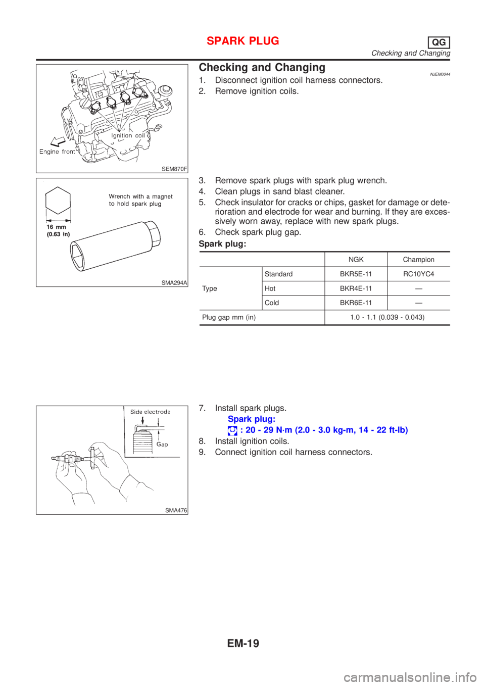
Checking and ChangingNJEM00441. Disconnect ignition coil harness connectors.
2. Remove ignition coils.
SMA294A
3. Remove spark plugs with spark plug wrench.
4. Clean plugs in sand blast cleaner.
5. Check insulator for cracks or chips, gasket for damage or dete-
rioration and electrode for wear and burning. If they are exces-
sively worn away, replace with new spark plugs.
6. Check spark plug gap.
Spark plug:
NGK Champion
TypeStandard BKR5E-11 RC10YC4
Hot BKR4E-11 Ð
Cold BKR6E-11 Ð
Plug gap mm (in) 1.0 - 1.1 (0.039 - 0.043)
SMA476
7. Install spark plugs.
Spark plug:
: 20 - 29 N´m (2.0 - 3.0 kg-m, 14 - 22 ft-lb)
8. Install ignition coils.
9. Connect ignition coil harness connectors.
SPARK PLUGQG
Checking and Changing
EM-19
Page 2237 of 2898
JEM140G
1. Install rear chain case.
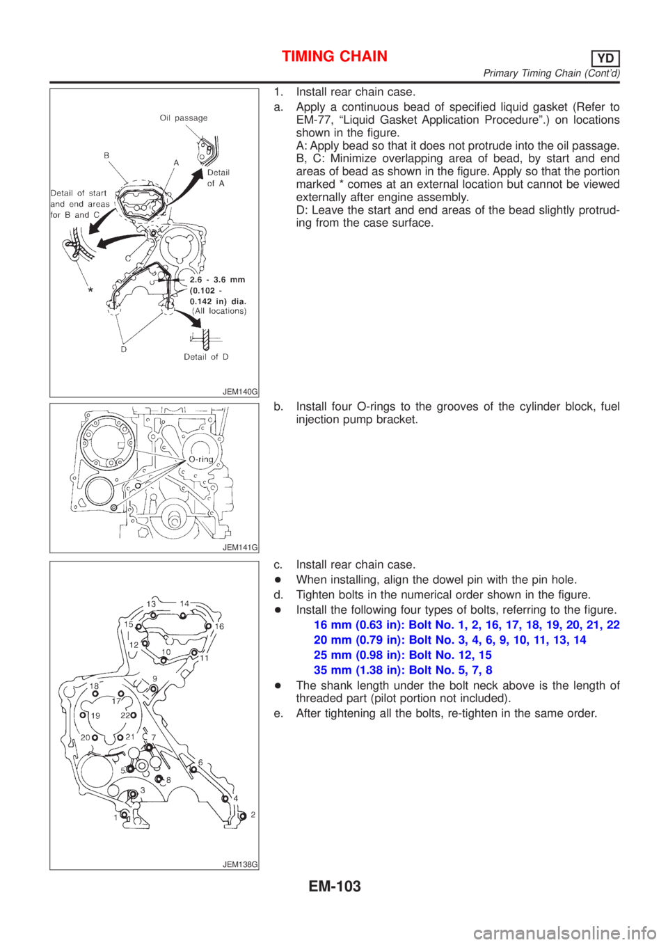
a. Apply a continuous bead of specified liquid gasket (Refer to
EM-77, ªLiquid Gasket Application Procedureº.) on locations
shown in the figure.
A: Apply bead so that it does not protrude into the oil passage.
B, C: Minimize overlapping area of bead, by start and end
areas of bead as shown in the figure. Apply so that the portion
marked * comes at an external location but cannot be viewed
externally after engine assembly.
D: Leave the start and end areas of the bead slightly protrud-
ing from the case surface.
JEM141G
b. Install four O-rings to the grooves of the cylinder block, fuel
injection pump bracket.
JEM138G
c. Install rear chain case.
+When installing, align the dowel pin with the pin hole.
d. Tighten bolts in the numerical order shown in the figure.
+Install the following four types of bolts, referring to the figure.
16 mm (0.63 in): Bolt No. 1, 2, 16, 17, 18, 19, 20, 21, 22
20 mm (0.79 in): Bolt No. 3, 4, 6, 9, 10, 11, 13, 14
25 mm (0.98 in): Bolt No. 12, 15
35 mm (1.38 in): Bolt No. 5, 7, 8
+The shank length under the bolt neck above is the length of
threaded part (pilot portion not included).
e. After tightening all the bolts, re-tighten in the same order.
TIMING CHAINYD
Primary Timing Chain (Cont'd)
EM-103