2001 NISSAN ALMERA tire pressure
[x] Cancel search: tire pressurePage 36 of 2898

SAT007J
+Line pressure is increased to a maximum irrespective of the
throttle opening when fluid temperature drops to þ10ÉC (14ÉF).
This pressure rise is adopted to prevent a delay in clutch and
brake operation due to extreme drop of fluid viscosity at low
temperature.
SHIFT CONTROLNJAT0015S02The shift is regulated entirely by electronic control to accommodate
vehicle speed and varying engine operations. This is accomplished
by electrical signals transmitted by the revolution sensor and
throttle position sensor. This results in improved acceleration per-
formance and fuel economy.
SAT008J
Control of Shift Solenoid Valves A and BNJAT0015S0201The TCM activates shift solenoid valves A and B according to sig-
nals from the throttle position sensor and revolution sensor to
select the optimum gear position on the basis of the shift schedule
memorized in the TCM.
The shift solenoid valve performs simple ON-OFF operation. When
set to ªONº, the drain circuit closes and pilot pressure is applied to
the shift valve.
Relation Between Shift Solenoid Valves A and B and
Gear Positions
NJAT0015S0203
Shift solenoid valveGear position
D
1,21,11D2,22,12D3D4(OD) N-P
A ON (Closed) OFF (Open) OFF (Open) ON (Closed) ON (Closed)
B ON (Closed) ON (Closed) OFF (Open) OFF (Open) ON (Closed)
Control of Shift Valves A and BNJAT0015S0202
SAT009J
OVERALL SYSTEM
Control Mechanism (Cont'd)
AT-34
Page 595 of 2898
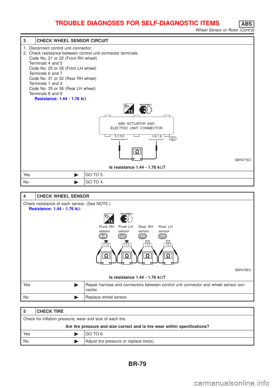
3 CHECK WHEEL SENSOR CIRCUIT
1. Disconnect control unit connector.
2. Check resistance between control unit connector terminals.
Code No. 21 or 22 (Front RH wheel)
Terminals 4 and 5
Code No. 25 or 26 (Front LH wheel)
Terminals 6 and 7
Code No. 31 or 32 (Rear RH wheel)
Terminals 1 and 3
Code No. 35 or 36 (Rear LH wheel)
Terminals 8 and 9
Resistance: 1.44 - 1.76 kW
SBR477EC
Is resistance 1.44 - 1.76 kW?
Ye s©GO TO 5.
No©GO TO 4.
4 CHECK WHEEL SENSOR
Check resistance of each sensor. (See NOTE.)
Resistance: 1.44 - 1.76 kW
SBR478EC
Is resistance 1.44 - 1.76 kW?
Ye s©Repair harness and connectors between control unit connector and wheel sensor con-
nector.
No©Replace wheel sensor.
5 CHECK TIRE
Check for inflation pressure, wear and size of each tire.
Are tire pressure and size correct and is tire wear within specifications?
Ye s©GO TO 6.
No©Adjust tire pressure or replace tire(s).
TROUBLE DIAGNOSES FOR SELF-DIAGNOSTIC ITEMSABS
Wheel Sensor or Rotor (Cont'd)
BR-79
Page 1623 of 2898
Aiming AdjustmentNJEL0016For details, refer to the regulations in your own country.
Before performing aiming adjustment, check the following.
1) Keep all tires inflated to correct pressures.
2) Place vehicle on flat surface.
3) See that there is no-load in vehicle (coolant, engine oil filled up
to correct level and full fuel tank) other than the driver (or
equivalent weight placed in driver's position).
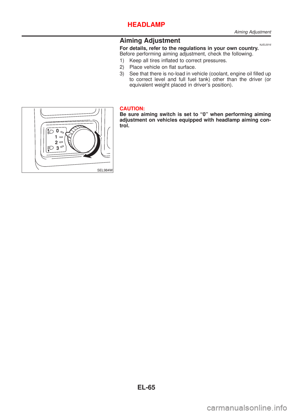
SEL984W
CAUTION:
Be sure aiming switch is set to ª0º when performing aiming
adjustment on vehicles equipped with headlamp aiming con-
trol.
HEADLAMP
Aiming Adjustment
EL-65
Page 1650 of 2898
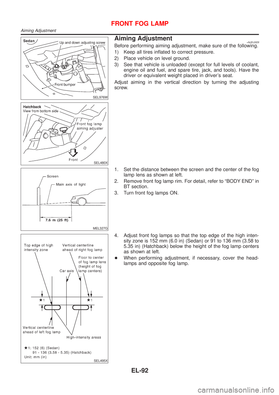
SEL976W
SEL480X
Aiming Adjustment=NJEL0029Before performing aiming adjustment, make sure of the following.
1) Keep all tires inflated to correct pressure.
2) Place vehicle on level ground.
3) See that vehicle is unloaded (except for full levels of coolant,
engine oil and fuel, and spare tire, jack, and tools). Have the
driver or equivalent weight placed in driver's seat.
Adjust aiming in the vertical direction by turning the adjusting
screw.
MEL327G
1. Set the distance between the screen and the center of the fog
lamp lens as shown at left.
2. Remove front fog lamp rim. For detail, refer to ªBODY ENDº in
BT section.
3. Turn front fog lamps ON.
SEL495X
4. Adjust front fog lamps so that the top edge of the high inten-
sity zone is 152 mm (6.0 in) (Sedan) or 91 to 136 mm (3.58 to
5.35 in) (Hatchback) below the height of the fog lamp centers
as shown at left.
+When performing adjustment, if necessary, cover the head-
lamps and opposite fog lamp.
FRONT FOG LAMP
Aiming Adjustment
EL-92
Page 2034 of 2898
Self-diagnosis ModeNJEL0519APPLICATION ITEMSNJEL0519S01
Mode DescriptionReference
page
Self DiagnosisSelf-diagnosis for Navigation, Display and GPS Antenna
connection.EL-477
Confirmation/
adjustmentDiagnose the DisplayColor and gray gradation of display can be checked in
this mode.EL-485
Diagnosis for Signals from the CarSeveral input signals to NAVI control unit, can be moni-
tored in this mode.EL-483
NavigationCheck the map CD-
ROM versionThe version (parts number) of inserted CD-ROM can be
checked in this model.EL-484
Error historyDiagnosis results previously stored in the memory
(before turning ignition switch ON) are displayed in this
mode. Time and location when/where the errors
occurred are also displayed.EL-479
Longitude & LatitudeDisplay the map. Use the joystick to adjust position. Lon-
gitude and latitude will be displayed.EL-486
Adjust the AngleTurning angle of the vehicle on the display can be
adjusted in this mode.EL-487
Speed CalibrationUnder ordinary conditions, the navigation system dis-
tance measuring function will automatically compensate
for minute decreases in wheel and tire diameter caused
by tire wear or low pressure. Speed calibration immedi-
ately restores system accuracy in cases such as when
distance calibration is needed because of the use of tire
chains in inclement weather.EL-488
Initialize LocationThis mode is for initializing the current location. Use
when the vehicle is transported a long distance by a
trailer, etc.EL-489
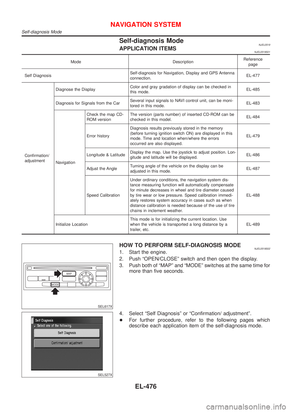
MODEMAP
SEL617X
HOW TO PERFORM SELF-DIAGNOSIS MODENJEL0519S021. Start the engine.
2. Push ªOPEN/CLOSEº switch and then open the display.
3. Push both of ªMAPº and ªMODEº switches at the same time for
more than five seconds.
SEL527X
4. Select ªSelf Diagnosisº or ªConfirmation/ adjustmentº.
+For further procedure, refer to the following pages which
describe each application item of the self-diagnosis mode.
NAVIGATION SYSTEM
Self-diagnosis Mode
EL-476
Page 2531 of 2898
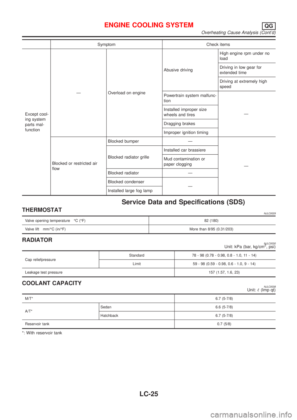
Symptom Check items
Except cool-
ing system
parts mal-
functionÐ Overload on engineAbusive drivingHigh engine rpm under no
load
Driving in low gear for
extended time
Driving at extremely high
speed
Powertrain system malfunc-
tion
Ð Installed improper size
wheels and tires
Dragging brakes
Improper ignition timing
Blocked or restricted air
flowBlocked bumper Ð
Ð Blocked radiator grilleInstalled car brassiere
Mud contamination or
paper clogging
Blocked radiator Ð
Blocked condenser
Ð
Installed large fog lamp
Service Data and Specifications (SDS)
THERMOSTATNJLC0029
Valve opening temperature ÉC (ÉF) 82 (180)
Valve lift mm/ÉC (in/ÉF)More than 8/95 (0.31/203)
RADIATORNJLC0030Unit: kPa (bar, kg/cm2, psi)
Cap reliefpressureStandard 78 - 98 (0.78 - 0.98, 0.8 - 1.0, 11 - 14)
Limit 59 - 98 (0.59 - 0.98, 0.6 - 1.0,9-14)
Leakage test pressure157 (1.57, 1.6, 23)
COOLANT CAPACITYNJLC0038Unit:!(Imp qt)
M/T*6.7 (5-7/8)
A/T*Sedan 6.6 (5-7/8)
Hatchback 6.7 (5-7/8)
Reservoir tank0.7 (5/8)
*: With reservoir tank
ENGINE COOLING SYSTEMQG
Overheating Cause Analysis (Cont'd)
LC-25
Page 2554 of 2898
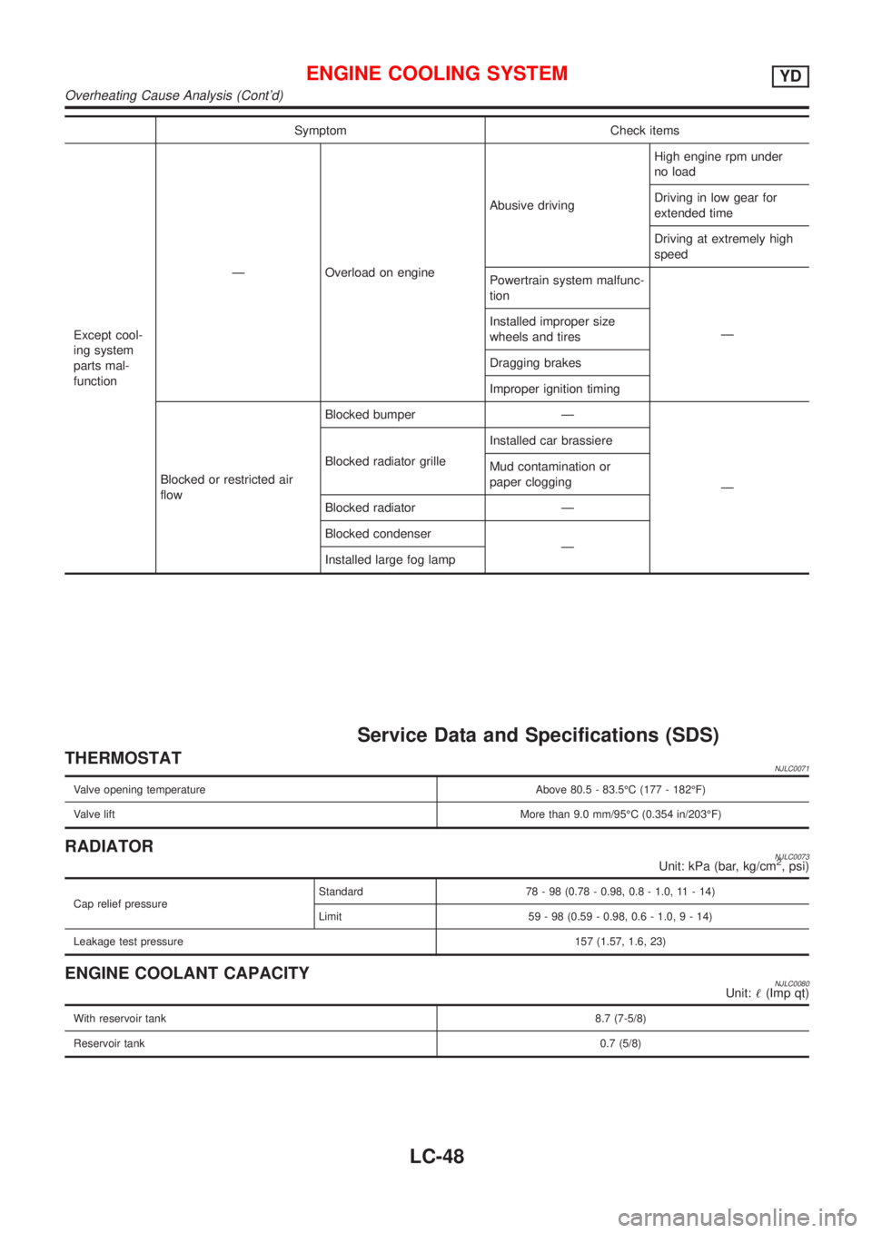
Symptom Check items
Except cool-
ing system
parts mal-
functionÐ Overload on engineAbusive drivingHigh engine rpm under
no load
Driving in low gear for
extended time
Driving at extremely high
speed
Powertrain system malfunc-
tion
Ð Installed improper size
wheels and tires
Dragging brakes
Improper ignition timing
Blocked or restricted air
flowBlocked bumper Ð
Ð Blocked radiator grilleInstalled car brassiere
Mud contamination or
paper clogging
Blocked radiator Ð
Blocked condenser
Ð
Installed large fog lamp
Service Data and Specifications (SDS)
THERMOSTATNJLC0071
Valve opening temperature Above 80.5 - 83.5ÉC (177 - 182ÉF)
Valve liftMore than 9.0 mm/95ÉC (0.354 in/203ÉF)
RADIATORNJLC0073Unit: kPa (bar, kg/cm2, psi)
Cap relief pressureStandard 78 - 98 (0.78 - 0.98, 0.8 - 1.0, 11 - 14)
Limit 59 - 98 (0.59 - 0.98, 0.6 - 1.0,9-14)
Leakage test pressure157 (1.57, 1.6, 23)
ENGINE COOLANT CAPACITYNJLC0080Unit:!(Imp qt)
With reservoir tank8.7 (7-5/8)
Reservoir tank0.7 (5/8)
ENGINE COOLING SYSTEMYD
Overheating Cause Analysis (Cont'd)
LC-48
Page 2556 of 2898
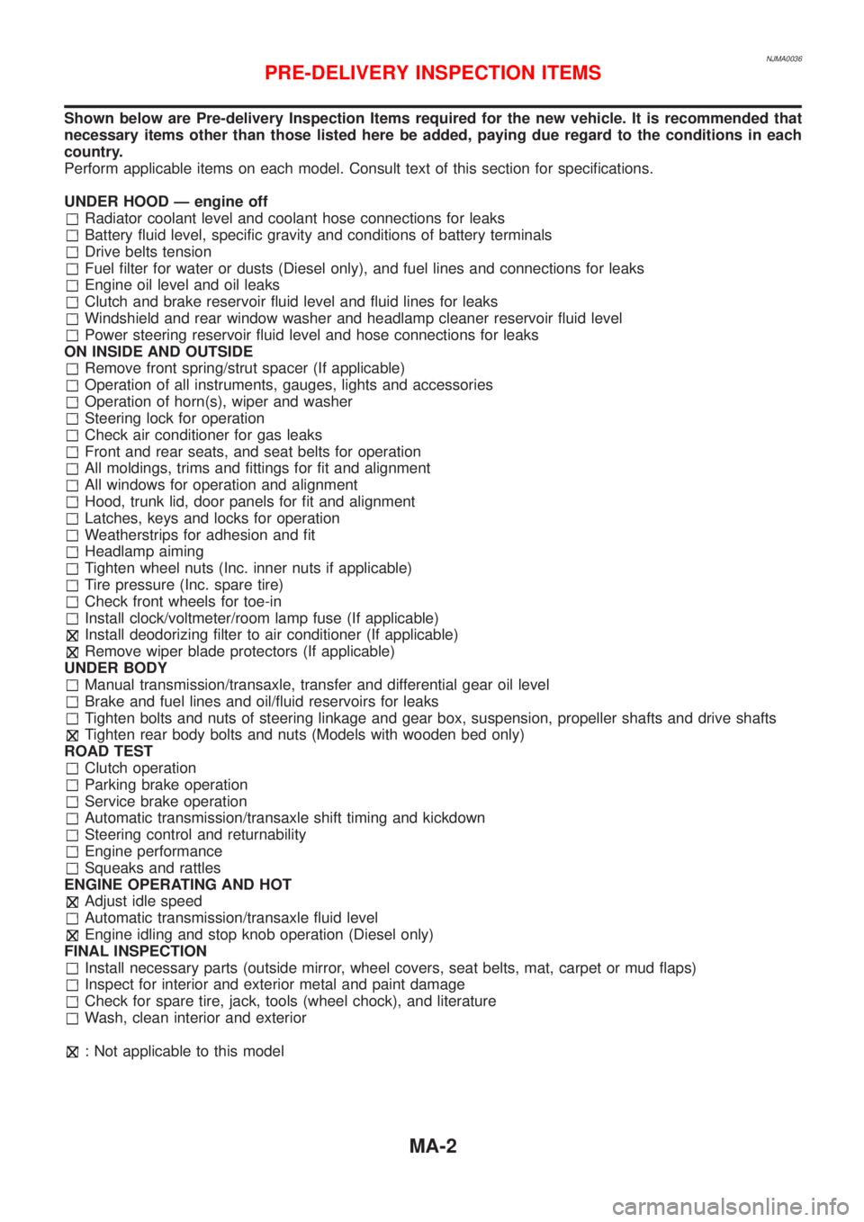
NJMA0036
Shown below are Pre-delivery Inspection Items required for the new vehicle. It is recommended that
necessary items other than those listed here be added, paying due regard to the conditions in each
country.
Perform applicable items on each model. Consult text of this section for specifications.
UNDER HOOD Ð engine off
Radiator coolant level and coolant hose connections for leaks
Battery fluid level, specific gravity and conditions of battery terminals
Drive belts tension
Fuel filter for water or dusts (Diesel only), and fuel lines and connections for leaks
Engine oil level and oil leaks
Clutch and brake reservoir fluid level and fluid lines for leaks
Windshield and rear window washer and headlamp cleaner reservoir fluid level
Power steering reservoir fluid level and hose connections for leaks
ON INSIDE AND OUTSIDE
Remove front spring/strut spacer (If applicable)
Operation of all instruments, gauges, lights and accessories
Operation of horn(s), wiper and washer
Steering lock for operation
Check air conditioner for gas leaks
Front and rear seats, and seat belts for operation
All moldings, trims and fittings for fit and alignment
All windows for operation and alignment
Hood, trunk lid, door panels for fit and alignment
Latches, keys and locks for operation
Weatherstrips for adhesion and fit
Headlamp aiming
Tighten wheel nuts (Inc. inner nuts if applicable)
Tire pressure (Inc. spare tire)
Check front wheels for toe-in
Install clock/voltmeter/room lamp fuse (If applicable)
Install deodorizing filter to air conditioner (If applicable)
Remove wiper blade protectors (If applicable)
UNDER BODY
Manual transmission/transaxle, transfer and differential gear oil level
Brake and fuel lines and oil/fluid reservoirs for leaks
Tighten bolts and nuts of steering linkage and gear box, suspension, propeller shafts and drive shafts
Tighten rear body bolts and nuts (Models with wooden bed only)
ROAD TEST
Clutch operation
Parking brake operation
Service brake operation
Automatic transmission/transaxle shift timing and kickdown
Steering control and returnability
Engine performance
Squeaks and rattles
ENGINE OPERATING AND HOT
Adjust idle speed
Automatic transmission/transaxle fluid level
Engine idling and stop knob operation (Diesel only)
FINAL INSPECTION
Install necessary parts (outside mirror, wheel covers, seat belts, mat, carpet or mud flaps)
Inspect for interior and exterior metal and paint damage
Check for spare tire, jack, tools (wheel chock), and literature
Wash, clean interior and exterior
: Not applicable to this model
PRE-DELIVERY INSPECTION ITEMS
MA-2