2001 NISSAN ALMERA automatic transmission
[x] Cancel search: automatic transmissionPage 17 of 2898

SMA827CA
Checking A/T FluidNJAT02281. Warm up engine.
2. Check for fluid leakage.
3. Before driving, fluid level can be checked at fluid temperatures
of 30 to 50ÉC (86 to 122ÉF) using ªCOLDº range on dipstick.
a. Park vehicle on level surface and set parking brake.
b. Start engine and move selector lever through each gear posi-
tion. Leave selector lever in ªPº position.
c. Check fluid level with engine idling.
d. Remove dipstick and note reading. If level is at low side of
either range, and fluid to the charging pipe.
e. Re-insert dipstick into charging pipe as far as it will go.
f. Remove dipstick and note reading. If reading is at low side of
range, add fluid to the charging pipe.
Do not overfill.
4. Drive vehicle for approximately 5 minutes in urban areas.
5. Re-check fluid level at fluid temperatures of 50 to 80ÉC (122
to 176ÉF) using ªHOTº range on dipstick.
SMA853B
6. Check fluid condition.
+If fluid is very dark or smells burned, refer to AT section for
checking operation of A/T. Flush cooling system after repair of
A/T.
+If A/T fluid contains frictional material (clutches, bands, etc.),
replace radiator and flush cooler line using cleaning solvent
and compressed air after repair of A/T. Refer to LC-16, ªRadia-
torº.
SMA027D
Changing A/T FluidNJAT02291. Warm up A/T fluid.
2. Stop engine.
3. Drain A/T fluid from drain plug and refill with new A/T fluid.
Always refill same volume with drained fluid.
Fluid grade:
Nissan Matic ªDº or Genuine Nissan Automatic
Transmission Fluid. Refer to ªRECOMMENDED FLU-
IDS AND LUBRICANTSº, MA-16.
Fluid capacity (With torque converter):
7.0!(6-1/8 Imp qt)
Drain plug:
: 29 - 39 N´m (3.0 - 4.0 kg-m, 22 - 29 ft-lb)
4. Run engine at idle speed for five minutes.
5. Check fluid level and condition. Refer to ªChecking A/T Fluidº.
If fluid is still dirty, repeat steps 2 through 5.
A/T FLUID
Checking A/T Fluid
AT-15
Page 25 of 2898
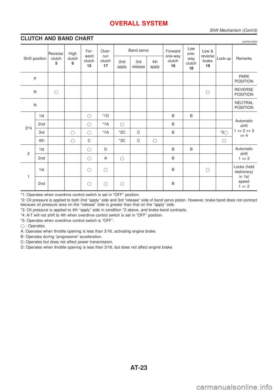
CLUTCH AND BAND CHARTNJAT0013S04
Shift positionReverse
clutch
5High
clutch
6For-
ward
clutch
15Over-
run
clutch
17Band servo
Forward
one-way
clutch
16Low
one-
way
clutch
18Low &
reverse
brake
19Lock-up Remarks
2nd
apply3rd
release4th
apply
PPARK
POSITION
RjjREVERSE
POSITION
NNEUTRAL
POSITION
D*41stj*1D B B
Automatic
shift
1Û2Û3
Û4 2ndj*1AjB
3rdjj*1A *2C C B *5j
4thjC *3C Cjj
21stjDBBAutomatic
shift
1Û2 2ndjAjB
11stjjBjLocks (held
stationary)
in 1st
speed
1Ü2 2ndjjjB
*1: Operates when overdrive control switch is set in ªOFFº position.
*2: Oil pressure is applied to both 2nd ªapplyº side and 3rd ªreleaseº side of band servo piston. However, brake band does not contract
because oil pressure area on the ªreleaseº side is greater than that on the ªapplyº side.
*3: Oil pressure is applied to 4th ªapplyº side in condition *2 above, and brake band contracts.
*4: A/T will not shift to 4th when overdrive control switch is set in ªOFFº position.
*5: Operates when overdrive control switch is ªOFFº.
j: Operates.
A: Operates when throttle opening is less than 3/16, activating engine brake.
B: Operates during ªprogressiveº acceleration.
C: Operates but does not affect power transmission.
D: Operates when throttle opening is less than 3/16, but does not affect engine brake.
OVERALL SYSTEM
Shift Mechanism (Cont'd)
AT-23
Page 35 of 2898

SAT003J
Normal ControlNJAT0015S0101The line pressure to throttle opening characteristics is set for suit-
able clutch operation.
SAT004J
Back-up Control (Engine brake)NJAT0015S0102If the selector lever is shifted to ª2º position while driving in D4(OD)
or D
3, great driving force is applied to the clutch inside the trans-
mission. Clutch operating pressure (line pressure) must be
increased to deal with this driving force.
SAT005J
During Shift ChangeNJAT0015S0103The line pressure is temporarily reduced corresponding to a
change in engine torque when shifting gears (that is, when the shift
solenoid valve is switched for clutch operation) to reduce shifting
shock.
At Low Fluid TemperatureNJAT0015S0104+Fluid viscosity and frictional characteristics of the clutch facing
change with fluid temperature. Clutch engaging or band-con-
tacting pressure is compensated for, according to fluid
temperature, to stabilize shifting quality.
SAT006J
+The line pressure is reduced below 60ÉC (140ÉF) to prevent
shifting shock due to low viscosity of automatic transmission
fluid when temperature is low.
OVERALL SYSTEM
Control Mechanism (Cont'd)
AT-33
Page 1158 of 2898
System DescriptionNJEC0573The malfunction information related to A/T (Automatic Transaxle) is transferred through the line (circuit) from
TCM (Transmission Control Module) to ECM. Therefore, be sure to erase the malfunction information such as
DTC not only in TCM (Transmission Control Module) but also ECM after the A/T related repair.
ECM Terminals and Reference ValueNJEC0574Specification data are reference values and are measured between each terminal and ground.
CAUTION:
Do not use ECM ground terminals when measuring input/output voltage. Doing so may result in dam-
age to the ECM's transistor. Use a ground other than ECM terminals, such as the ground.
TERMI-
NAL
NO.WIRE
COLORITEM CONDITION DATA (DC Voltage)
91 PU A/T check signal[Ignition switch ªONº]0 - Approximately 5V
On Board Diagnosis LogicNJEC0575
DTC No. Malfunction is detected when ... Check Items (Possible Cause)
P1605
1605+An incorrect signal from TCM (Transmission Control
Module) is sent to ECM.+Harness or connectors
[The communication line circuit between ECM
and TCM (Transmission Control Module) is open
or shorted.]
+Dead (Weak) battery
+TCM (Transmission Control Module)
SEF058Y
DTC Confirmation ProcedureNJEC0576NOTE:
If ªDTC CONFIRMATION PROCEDUREº has been previously
conducted, always turn ignition switch ªOFFº and wait at least 9
seconds before conducting the next test.
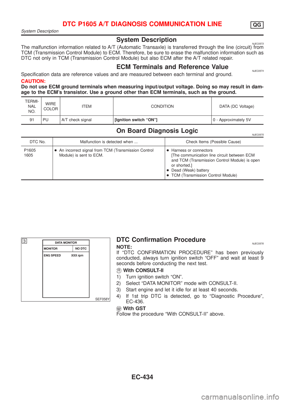
With CONSULT-II
1) Turn ignition switch ªONº.
2) Select ªDATA MONITORº mode with CONSULT-II.
3) Start engine and let it idle for at least 40 seconds.
4) If 1st trip DTC is detected, go to ªDiagnostic Procedureº,
EC-436.
With GST
Follow the procedure ªWith CONSULT-IIº above.
DTC P1605 A/T DIAGNOSIS COMMUNICATION LINEQG
System Description
EC-434
Page 2352 of 2898
Do not attempt to top off the fuel tank after the fuel pump nozzle
shuts off automatically. Continued refueling may cause fuel
overflow, resulting in fuel spray and possibly a fire.
WARNING:
To prevent ECM from storing the diagnostic trouble codes, do
not carelessly disconnect the harness connectors which are
related to the engine control system and TCM (Transmission
Control Module) system. The connectors should be discon-
nected only when working according to the WORK FLOW of
TROUBLE DIAGNOSES in EC and AT sections.
SGI787
PRECAUTIONS FOR MULTIPORT FUEL INJECTION
SYSTEM OR ENGINE CONTROL SYSTEM
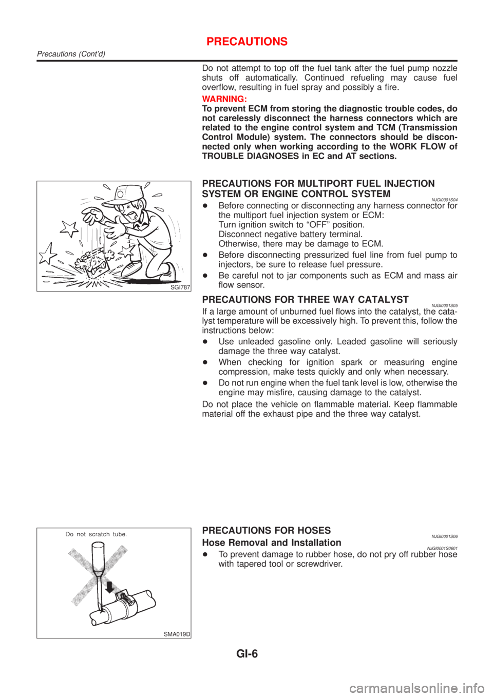
NJGI0001S04+Before connecting or disconnecting any harness connector for
the multiport fuel injection system or ECM:
Turn ignition switch to ªOFFº position.
Disconnect negative battery terminal.
Otherwise, there may be damage to ECM.
+Before disconnecting pressurized fuel line from fuel pump to
injectors, be sure to release fuel pressure.
+Be careful not to jar components such as ECM and mass air
flow sensor.
PRECAUTIONS FOR THREE WAY CATALYSTNJGI0001S05If a large amount of unburned fuel flows into the catalyst, the cata-
lyst temperature will be excessively high. To prevent this, follow the
instructions below:
+Use unleaded gasoline only. Leaded gasoline will seriously
damage the three way catalyst.
+When checking for ignition spark or measuring engine
compression, make tests quickly and only when necessary.
+Do not run engine when the fuel tank level is low, otherwise the
engine may misfire, causing damage to the catalyst.
Do not place the vehicle on flammable material. Keep flammable
material off the exhaust pipe and the three way catalyst.
SMA019D
PRECAUTIONS FOR HOSESNJGI0001S06Hose Removal and InstallationNJGI0001S0601+To prevent damage to rubber hose, do not pry off rubber hose
with tapered tool or screwdriver.
PRECAUTIONS
Precautions (Cont'd)
GI-6
Page 2355 of 2898
NJGI0002
+The captionsWARNINGandCAUTIONwarm you of steps that must be followed to prevent personal injury
and/or damage to some part of the vehicle.
WARNINGindicates the possibility of personal injury if instructions are not followed.
CAUTIONindicates the possibility of component damage if instructions are not followed.
BOLD TYPED STATEMENTSexceptWARNINGandCAUTIONgive you helpful information.
+ALPHABETICAL INDEXis provided at the end of this manual so that you can rapidly find the item and
page you are searching for.
+A QUICK REFERENCE INDEX, a black tab (e.g.
) is provided on the first page. You can quickly find
the first page of each section by matching it to the section's black tab.
+THE CONTENTSare listed on the first page of each section.
+THE TITLEis indicated on the upper portion of each page and shows the part or system.
+THE PAGE NUMBERof each section consists of two letters which designate the particular section and a
number (e.g. ªBR-5º).
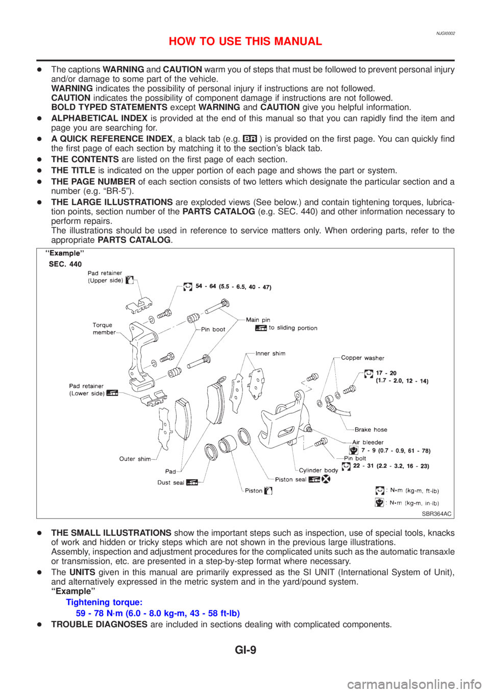
+THE LARGE ILLUSTRATIONSare exploded views (See below.) and contain tightening torques, lubrica-
tion points, section number of thePARTS CATALOG(e.g. SEC. 440) and other information necessary to
perform repairs.
The illustrations should be used in reference to service matters only. When ordering parts, refer to the
appropriatePARTS CATALOG.
SBR364AC
+THE SMALL ILLUSTRATIONSshow the important steps such as inspection, use of special tools, knacks
of work and hidden or tricky steps which are not shown in the previous large illustrations.
Assembly, inspection and adjustment procedures for the complicated units such as the automatic transaxle
or transmission, etc. are presented in a step-by-step format where necessary.
+TheUNITSgiven in this manual are primarily expressed as the SI UNIT (International System of Unit),
and alternatively expressed in the metric system and in the yard/pound system.
ªExampleº
Tightening torque:
59 - 78 N´m (6.0 - 8.0 kg-m, 43 - 58 ft-lb)
+TROUBLE DIAGNOSESare included in sections dealing with complicated components.
HOW TO USE THIS MANUAL
GI-9
Page 2356 of 2898
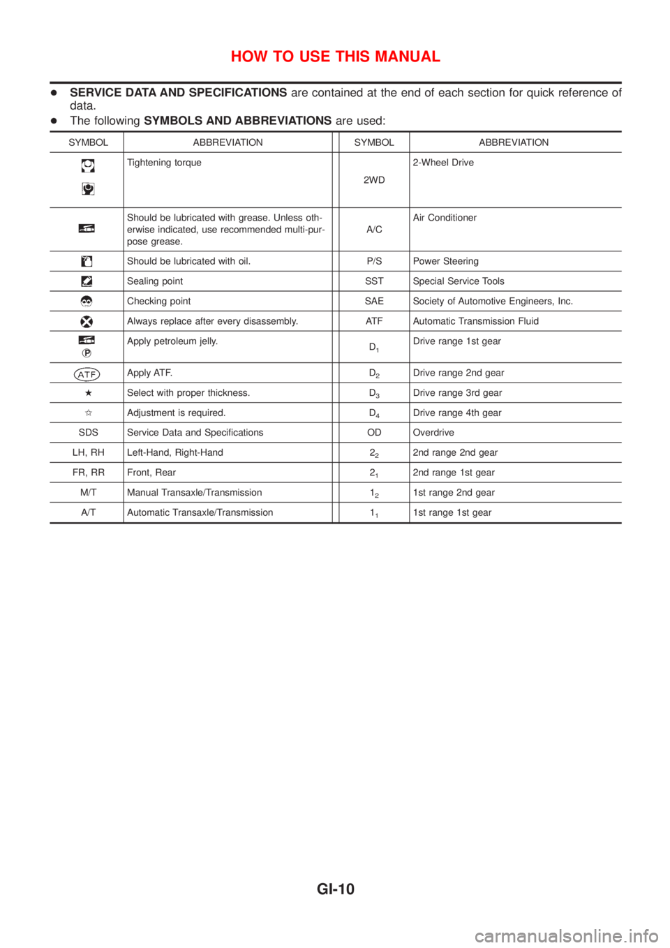
+SERVICE DATA AND SPECIFICATIONSare contained at the end of each section for quick reference of
data.
+The followingSYMBOLS AND ABBREVIATIONSare used:
SYMBOL ABBREVIATION SYMBOL ABBREVIATION
Tightening torque
2WD2-Wheel Drive
Should be lubricated with grease. Unless oth-
erwise indicated, use recommended multi-pur-
pose grease.A/CAir Conditioner
Should be lubricated with oil. P/S Power Steering
Sealing point SST Special Service Tools
Checking point SAE Society of Automotive Engineers, Inc.
Always replace after every disassembly. ATF Automatic Transmission Fluid
jP
Apply petroleum jelly.
D1Drive range 1st gear
Apply ATF. D2Drive range 2nd gear
HSelect with proper thickness. D
3Drive range 3rd gear
IAdjustment is required. D
4Drive range 4th gear
SDS Service Data and Specifications OD Overdrive
LH, RH Left-Hand, Right-Hand 2
22nd range 2nd gear
FR, RR Front, Rear 2
12nd range 1st gear
M/T Manual Transaxle/Transmission 1
21st range 2nd gear
A/T Automatic Transaxle/Transmission 1
11st range 1st gear
HOW TO USE THIS MANUAL
GI-10
Page 2393 of 2898
SGI805
SGI987
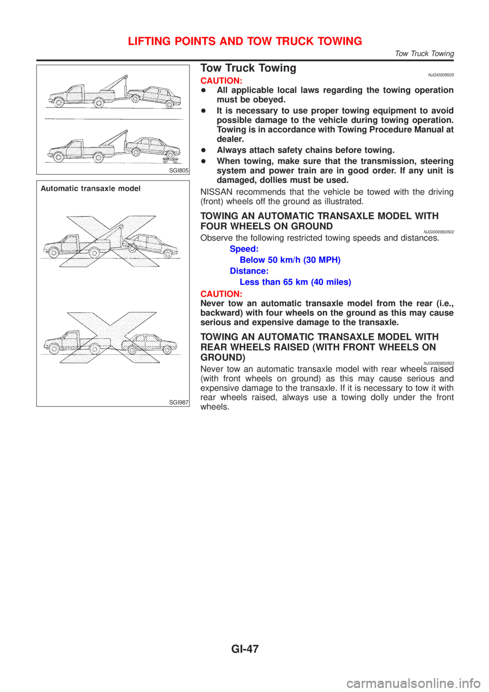
Tow Truck TowingNJGI0009S05CAUTION:
+All applicable local laws regarding the towing operation
must be obeyed.
+It is necessary to use proper towing equipment to avoid
possible damage to the vehicle during towing operation.
Towing is in accordance with Towing Procedure Manual at
dealer.
+Always attach safety chains before towing.
+When towing, make sure that the transmission, steering
system and power train are in good order. If any unit is
damaged, dollies must be used.
NISSAN recommends that the vehicle be towed with the driving
(front) wheels off the ground as illustrated.
TOWING AN AUTOMATIC TRANSAXLE MODEL WITH
FOUR WHEELS ON GROUND
NJGI0009S0502Observe the following restricted towing speeds and distances.
Speed:
Below 50 km/h (30 MPH)
Distance:
Less than 65 km (40 miles)
CAUTION:
Never tow an automatic transaxle model from the rear (i.e.,
backward) with four wheels on the ground as this may cause
serious and expensive damage to the transaxle.
TOWING AN AUTOMATIC TRANSAXLE MODEL WITH
REAR WHEELS RAISED (WITH FRONT WHEELS ON
GROUND)
NJGI0009S0503Never tow an automatic transaxle model with rear wheels raised
(with front wheels on ground) as this may cause serious and
expensive damage to the transaxle. If it is necessary to tow it with
rear wheels raised, always use a towing dolly under the front
wheels.
LIFTING POINTS AND TOW TRUCK TOWING
Tow Truck Towing
GI-47