2001 NISSAN ALMERA check engine light
[x] Cancel search: check engine lightPage 5 of 2898

Component Inspection .............................................251
DTC P0755 SHIFT SOLENOID VALVE B..................252
Description ...............................................................252
Wiring Diagram - AT - SSV/B ..................................254
Diagnostic Procedure ..............................................255
Component Inspection .............................................257
DTC P1705 THROTTLE POSITION SENSOR...........258
Description ...............................................................258
Wiring Diagram - AT - TPS ......................................261
Diagnostic Procedure ..............................................263
Component Inspection .............................................267
DTC P1760 OVERRUN CLUTCH SOLENOID
VALVE..........................................................................268
Description ...............................................................268
Wiring Diagram - AT - OVRCSV..............................270
Diagnostic Procedure ..............................................271
Component Inspection .............................................273
DTC BATT/FLUID TEMP SEN (A/T FLUID TEMP
SENSOR CIRCUIT AND TCM POWER SOURCE)....274
Description ...............................................................274
Wiring Diagram - AT - BA/FTS ................................276
Diagnostic Procedure ..............................................277
Component Inspection .............................................280
DTC VHCL SPEED SEN.MTR VEHICLE SPEED
SENSOR.MTR..............................................................281
Description ...............................................................281
Wiring Diagram - AT - VSSMTR ..............................283
Diagnostic Procedure ..............................................285
DTC CONTROL UNIT (RAM), CONTROL UNIT
(ROM)...........................................................................286
Description ...............................................................286
Diagnostic Procedure ..............................................286
DTC CONTROL UNIT (EEP ROM).............................288
Description ...............................................................288
Diagnostic Procedure ..............................................289
TROUBLE DIAGNOSES FOR SYMPTOMS...............290
Wiring Diagram - AT - NONDTC/General and
Except for Euro-OBD ...............................................290
Wiring Diagram - AT - NONDTC/EURO-OBD .........292
1. O/D OFF Indicator Lamp Does Not Come On....296
2. Engine Cannot Be Started In²P²and²N²
Position ....................................................................299
3. In²P²Position, Vehicle Moves Forward Or
Backward When Pushed .........................................300
4. In²N²Position, Vehicle Moves ...........................301
5. Large Shock.²N²->²R²Position .......................303
6. Vehicle Does Not Creep Backward In²R²
Position ....................................................................305
7. Vehicle Does Not Creep Forward In²D²,²2²
Or²1²Position .........................................................3088. Vehicle Cannot Be Started From D
1................... 311
9. A/T Does Not Shift: D
1-> D2Or Does Not
Kickdown: D
4-> D2..................................................314
10. A/T Does Not Shift: D
2-> D3.............................317
11. A/T Does Not Shift: D
3-> D4.............................320
12. A/T Does Not Perform Lock-up .........................323
13. A/T Does Not Hold Lock-up Condition ..............325
14. Lock-up Is Not Released ...................................327
15. Engine Speed Does Not Return To Idle (Light
Braking D
4-> D3).....................................................328
16. Vehicle Does Not Start From D
1.......................330
17. A/T Does Not Shift: D
4-> D3, When
Overdrive Control Switch²ON²->²OFF²...............331
18. A/T Does Not Shift: D
3-> 22, When Selector
Lever²D²->²2²Position.........................................332
19. A/T Does Not Shift: 2
2-> 11, When Selector
Lever²2²->²1²Position .........................................333
20. Vehicle Does Not Decelerate By Engine
Brake........................................................................334
21. TCM Self-diagnosis Does Not Activate (PNP,
Overdrive Control and Throttle Position Switches
Circuit Checks) ........................................................334
A/T SHIFT LOCK SYSTEM.........................................343
Description ...............................................................343
Shift Lock System Electrical Parts Location............343
Wiring Diagram - SHIFT -........................................344
Diagnostic Procedure ..............................................345
KEY INTERLOCK CABLE..........................................349
Components.............................................................349
Removal ...................................................................349
Installation ................................................................350
ON-VEHICLE SERVICE..............................................351
Control Valve Assembly and Accumulators .............351
Control Cable Adjustment ........................................352
Park/Neutral Position (PNP) Switch Adjustment .....352
Differential Side Oil Seal Replacement ...................353
Revolution Sensor Replacement .............................353
REMOVAL AND INSTALLATION...............................354
Removal ...................................................................354
Installation ................................................................355
OVERHAUL.................................................................357
Components-1 3AX00, 3AX01, 3AX19, 3AX63
and 3AX64 models ..................................................357
Components-1 3AX10 and 3AX18 models .............358
Components-2 3AX00, 3AX01, 3AX19, 3AX63
and 3AX64 models ..................................................359
Components-2 3AX10 and 3AX18 models .............360
Components-3 3AX00, 3AX01, 3AX19, 3AX63
and 3AX64 models ..................................................361
Components-3 3AX10 and 3AX18 models .............362
Oil Channel ..............................................................363
CONTENTS(Cont'd)
AT-3
Page 56 of 2898

SAT964I
Malfunction Indicator (MI)=NJAT02551. The malfunction indicator will light up when the ignition switch
is turned ON without the engine running. This is for checking
the lamp.
+If the malfunction indicator does not light up, refer to EL-185,
ªWarning Lampsº.
(Or see MI & CONSULT-II in EC section. Refer to EC-74,
ªDescriptionº, ªMalfunction Indicator (MI)º and EC-83, ªCON-
SULT-IIº.)
2. When the engine is started, the malfunction indicator should go
off.
If the lamp remains on, the on board diagnostic system has
detected an emission-related (EURO-OBD) malfunction. For
detail, refer to EC-59, ªON BOARD DIAGNOSTIC SYSTEM
DESCRIPTIONº.
CONSULT-IINJAT0256After performing ªSELF-DIAGNOSTIC PROCEDURE (WITH CON-
SULT-II)º (AT-55), place check marks for results on the ªDIAGNOS-
TIC WORKSHEETº, AT-76. Reference pages are provided follow-
ing the items.
NOTICE:
1) The CONSULT-II electrically displays shift timing and lock-up
timing (that is, operation timing of each solenoid).
Check for time difference between actual shift timing and the
CONSULT-II display. If the difference is noticeable, mechani-
cal parts (except solenoids, sensors, etc.) may be malfunction-
ing. Check mechanical parts using applicable diagnostic pro-
cedures.
2) Shift schedule (which implies gear position) displayed on
CONSULT-II and that indicated in Service Manual may differ
slightly. This occurs because of the following reasons:
+Actual shift schedule has more or less tolerance or allowance,
+Shift schedule indicated in Service Manual refers to the point
where shifts start, and
+Gear position displayed on CONSULT-II indicates the point
where shifts are completed.
3) Shift solenoid valve ªAº or ªBº is displayed on CONSULT-II at
the start of shifting. Gear position is displayed upon completion
of shifting (which is computed by TCM).
4) Additional CONSULT-II information can be found in the Opera-
tion Manual supplied with the CONSULT-II unit.
ON BOARD DIAGNOSTIC SYSTEM
DESCRIPTION
EURO-OBD
Malfunction Indicator (MI)
AT-54
Page 74 of 2898

4. 4-3. Cruise testAT-92
AT-95
Part-1
N8. Vehicle Cannot Be Started From D
1, AT-311.
N9. A/T Does Not Shift: D
1®D2Or Does Not Kickdown: D4®D2, AT-314.
N10. A/T Does Not Shift: D
2®D3, AT-317.
N11. A/T Does Not Shift: D
3®D4, AT-320.
N12. A/T Does Not Perform Lock-up, AT-323.
N13. A/T Does Not Hold Lock-up Condition, AT-325.
N14. Lock-up Is Not Released, AT-327.
N15. Engine Speed Does Not Return To Idle (Light Braking D
4®D3), AT-328.
Part-2AT-99
N16. Vehicle Does Not Start From D
1, AT-330.
N9. A/T Does Not Shift: D
1®D2Or Does Not Kickdown: D4®D2, AT-314.
N10. A/T Does Not Shift: D
2®D3, AT-317.
N11. A/T Does Not Shift: D
3®D4, AT-320.
Part-3AT-101
N17. A/T Does Not Shift: D
4®D3When Overdrive Control Switch ªONº®ªOFFº, AT-331
N15. Engine Speed Does Not Return To Idle (Engine Brake In D
3), AT-328.
N18. A/T Does Not Shift: D
3®22, When Selector Lever ªDº®ª2º Position, AT-332.
N15. Engine Speed Does Not Return To Idle (Engine Brake In 2
2), AT-328.
N19. A/T Does Not Shift: 2
2®11, When Selector Lever ª2º®ª1º Position, AT-333.
N20. Vehicle Does Not Decelerate By Engine Brake, AT-334.
N21. TCM Self-diagnosis Does Not Activate (PNP, Overdrive Control and Throttle Position Switches
Circuit Checks), AT-334.
NSELF-DIAGNOSTIC PROCEDURE Ð Mark detected items.
NVehicle speed sensor´A/T (Revolution sensor), AT-126.
NVehicle speed sensor´MTR, AT-131.
NThrottle position sensor, AT-134.
NShift solenoid valve A, AT-142.
NShift solenoid valve B, AT-148.
NOverrun clutch solenoid valve, AT-154.
NTorque converter clutch solenoid valve, AT-159.
NA/T fluid temperature sensor and TCM power source, AT-165.
NEngine speed signal, AT-172.
NLine pressure solenoid valve, AT-176.
NControl unit (RAM), control unit (ROM), AT-286.
NControl unit (EEP ROM), AT-288.
NPNP, overdrive control and throttle position switches, AT-334.
NBattery
NOthers
5.NFor self-diagnosis NG items, inspect each component. Repair or replace the damaged parts. AT-40
6.NPerform all ROAD TEST and re-mark required procedures. AT-85
7.NPerform the Diagnostic Procedures for all remaining items marked NG. Repair or replace the damaged
parts.
Refer to the Symptom Chart when you perform the procedures. (The chart also shows some other possible
symptoms and the component inspection orders.)AT-118
AT-105
8.NErase self-diagnosis code from TCM memories. AT-43
AT-49
TROUBLE DIAGNOSIS Ð
INTRODUCTION
EXCEPT FOR EURO-OBD
Introduction (Cont'd)
AT-72
Page 79 of 2898

4. 4-3. Cruise testAT-92
AT-95
Part-1
N8. Vehicle Cannot Be Started From D
1, AT-311.
N9. A/T Does Not Shift: D
1®D2Or Does Not Kickdown: D4®D2, AT-314.
N10. A/T Does Not Shift: D
2®D3, AT-317.
N11. A/T Does Not Shift: D
3®D4, AT-320.
N12. A/T Does Not Perform Lock-up, AT-323.
N13. A/T Does Not Hold Lock-up Condition, AT-325.
N14. Lock-up Is Not Released, AT-327.
N15. Engine Speed Does Not Return To Idle (Light Braking D
4®D3), AT-328.
Part-2AT-99
N16. Vehicle Does Not Start From D
1, AT-330.
N9. A/T Does Not Shift: D
1®D2Or Does Not Kickdown: D4®D2, AT-314.
N10. A/T Does Not Shift: D
2®D3, AT-317.
N11. A/T Does Not Shift: D
3®D4, AT-320.
Part-3AT-101
N17. A/T Does Not Shift: D
4®D3When Overdrive Control Switch ªONº®ªOFFº, AT-331
N15. Engine Speed Does Not Return To Idle (Engine Brake In D
3), AT-328.
N18. A/T Does Not Shift: D
3®22, When Selector Lever ªDº®ª2º Position, AT-332.
N15. Engine Speed Does Not Return To Idle (Engine Brake In 2
2), AT-328.
N19. A/T Does Not Shift: 2
2®11, When Selector Lever ª2º®ª1º Position, AT-333.
N20. Vehicle Does Not Decelerate By Engine Brake, AT-334.
NSELF-DIAGNOSTIC PROCEDURE Ð Mark detected items.
NPNP switch, AT-183.
NA/T fluid temperature sensor, AT-189.
NVehicle speed sensor´A/T (Revolution sensor), AT-195.
NEngine speed signal, AT-200.
NTorque converter clutch solenoid valve, AT-233.
NLine pressure solenoid valve, AT-239.
NShift solenoid valve A, AT-246.
NShift solenoid valve B, AT-252.
NThrottle position sensor, AT-258.
NOverrun clutch solenoid valve, AT-268.
NPNP, overdrive control and throttle position switches, AT-334.
NA/T fluid temperature sensor and TCM power source, AT-274.
NVehicle speed sensor´MTR, AT-281.
NControl unit (RAM), control unit (ROM), AT-286.
NControl unit (EEP ROM), AT-288.
NBattery
NOthers
5.NFor self-diagnosis NG items, inspect each component. Repair or replace the damaged parts. AT-55
6.NPerform all ROAD TEST and re-mark required procedures. AT-85
7.NPerform DTC CONFIRMATION PROCEDURE for following MIL indicating items and check out NG items.
Refer to EC-60, ªEmission-related Diagnostic Informationº.EC section
NDTC (P0731) A/T 1st gear function, AT-204.
NDTC (P0732) A/T 2nd gear function, AT-211.
NDTC (P0733) A/T 3rd gear function, AT-217.
NDTC (P0734) A/T 4th gear function, AT-223.
8.NPerform the Diagnostic Procedures for all remaining items marked NG. Repair or replace the damaged
parts.
Refer to the Symptom Chart when you perform the procedures. (The chart also shows some other possible
symptoms and the component inspection orders.)AT-105
AT-118
9.NErase DTC from TCM and ECM memories. AT-52
TROUBLE DIAGNOSIS Ð INTRODUCTIONEURO-OBD
Introduction (Cont'd)
AT-77
Page 82 of 2898

SAT767B
A/T Fluid CheckNJAT0025FLUID LEAKAGE CHECKNJAT0025S011. Clean area suspected of leaking. Ð for example, mating sur-
face of converter housing and transmission case.
2. Start engine, apply foot brake, place selector lever in ªDº posi-
tion and wait a few minutes.
3. Stop engine.
SAT288G
4. Check for fresh leakage.
SAT638A
FLUID CONDITION CHECKNJAT0025S02
Fluid color Suspected problem
Dark or black with burned odor Wear of frictional material
Milky pink Water contamination Ð Road water
entering through filler tube or breather
Varnished fluid, light to dark brown
and tackyOxidation Ð Over or under filling, Ð
Overheating
FLUID LEVEL CHECKNJAT0025S03Refer to ªChecking A/T Fluidº, AT-15.
SAT647B
Stall TestNJAT0026STALL TEST PROCEDURENJAT0026S011. Check A/T fluid and engine oil levels. If necessary, add.
2. Drive vehicle for approx. 10 minutes or until fluid and oil reach
operating temperature.
ATF operating temperature:
50 - 80ÉC (122 - 176ÉF)
TROUBLE DIAGNOSIS Ð BASIC INSPECTION
A/T Fluid Check
AT-80
Page 100 of 2898

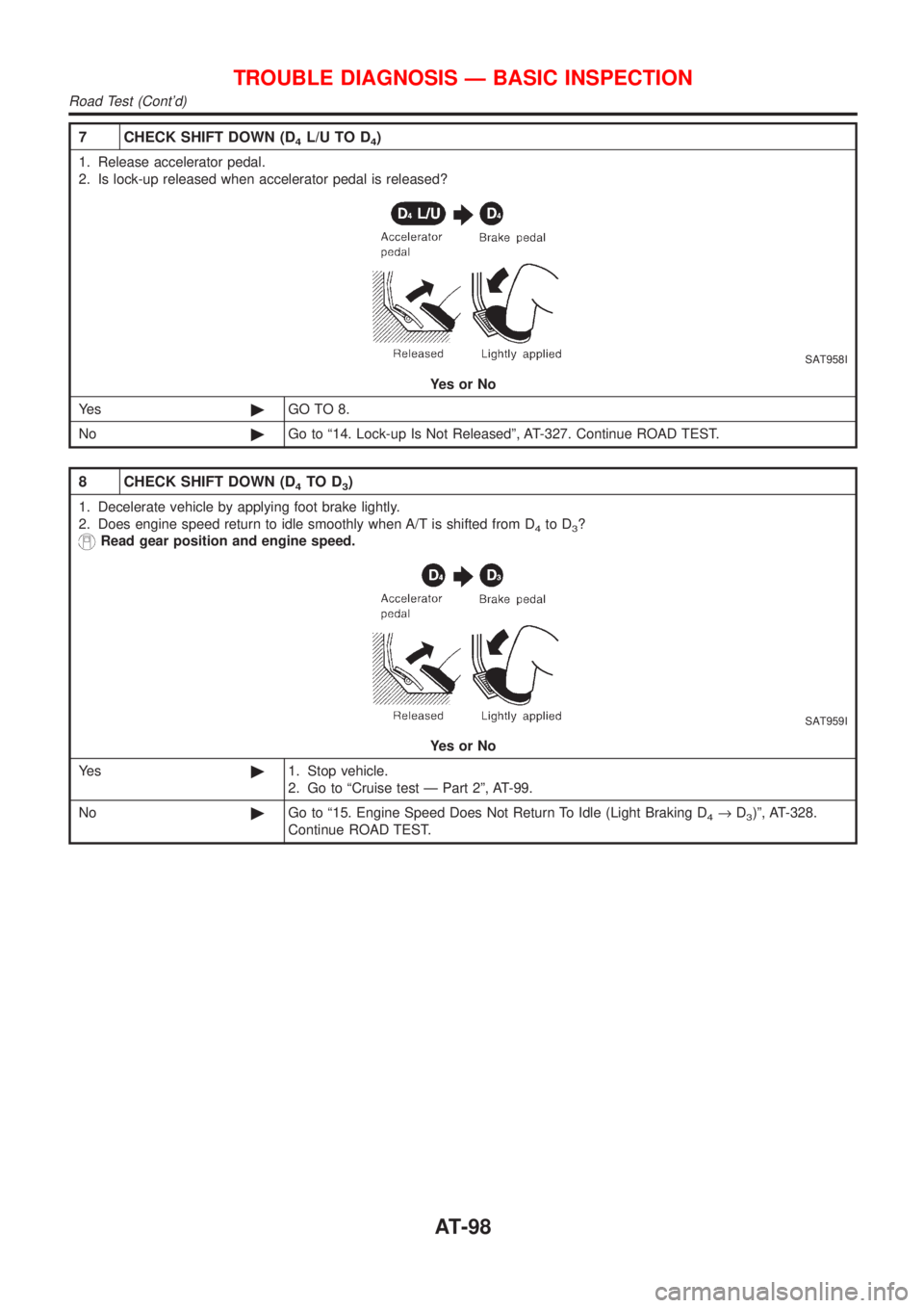
7 CHECK SHIFT DOWN (D4L/U TO D4)
1. Release accelerator pedal.
2. Is lock-up released when accelerator pedal is released?
SAT958I
YesorNo
Ye s©GO TO 8.
No©Go to ª14. Lock-up Is Not Releasedº, AT-327. Continue ROAD TEST.
8 CHECK SHIFT DOWN (D4TO D3)
1. Decelerate vehicle by applying foot brake lightly.
2. Does engine speed return to idle smoothly when A/T is shifted from D
4to D3?
Read gear position and engine speed.
SAT959I
YesorNo
Ye s©1. Stop vehicle.
2. Go to ªCruise test Ð Part 2º, AT-99.
No©Go to ª15. Engine Speed Does Not Return To Idle (Light Braking D
4®D3)º, AT-328.
Continue ROAD TEST.
TROUBLE DIAGNOSIS Ð BASIC INSPECTION
Road Test (Cont'd)
AT-98
Page 104 of 2898

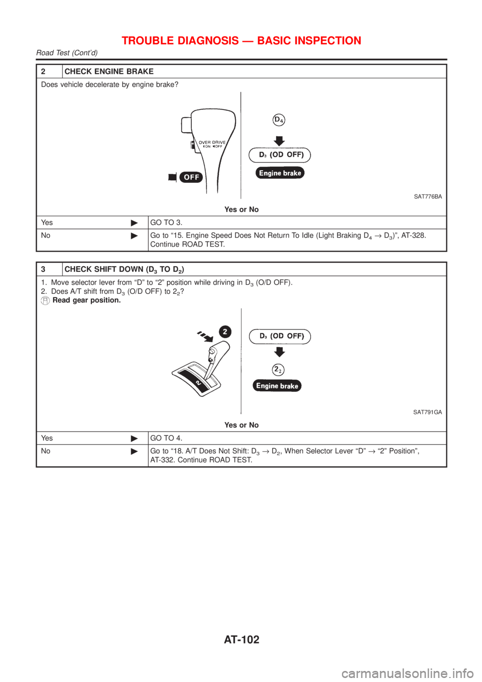
2 CHECK ENGINE BRAKE
Does vehicle decelerate by engine brake?
SAT776BA
YesorNo
Ye s©GO TO 3.
No©Go to ª15. Engine Speed Does Not Return To Idle (Light Braking D
4®D3)º, AT-328.
Continue ROAD TEST.
3 CHECK SHIFT DOWN (D3TO D2)
1. Move selector lever from ªDº to ª2º position while driving in D3(O/D OFF).
2. Does A/T shift from D
3(O/D OFF) to 22?
Read gear position.
SAT791GA
YesorNo
Ye s©GO TO 4.
No©Go to ª18. A/T Does Not Shift: D
3®D2, When Selector Lever ªDº®ª2º Positionº,
AT-332. Continue ROAD TEST.
TROUBLE DIAGNOSIS Ð BASIC INSPECTION
Road Test (Cont'd)
AT-102
Page 105 of 2898

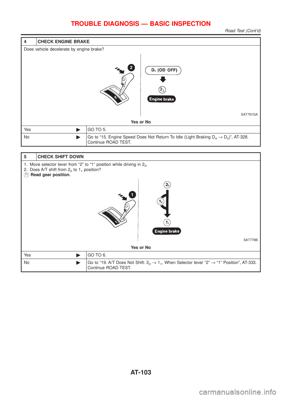
4 CHECK ENGINE BRAKE
Does vehicle decelerate by engine brake?
SAT791GA
YesorNo
Ye s©GO TO 5.
No©Go to ª15. Engine Speed Does Not Return To Idle (Light Braking D
4®D3)º, AT-328.
Continue ROAD TEST.
5 CHECK SHIFT DOWN
1. Move selector lever from ª2º to ª1º position while driving in 22.
2. Does A/T shift from 2
2to 11position?
Read gear position.
SAT778B
YesorNo
Ye s©GO TO 6.
No©Go to ª19. A/T Does Not Shift: 2
2®11, When Selector lever ª2º®ª1º Positionº, AT-333.
Continue ROAD TEST.
TROUBLE DIAGNOSIS Ð BASIC INSPECTION
Road Test (Cont'd)
AT-103