2001 NISSAN ALMERA wheel size
[x] Cancel search: wheel sizePage 595 of 2898
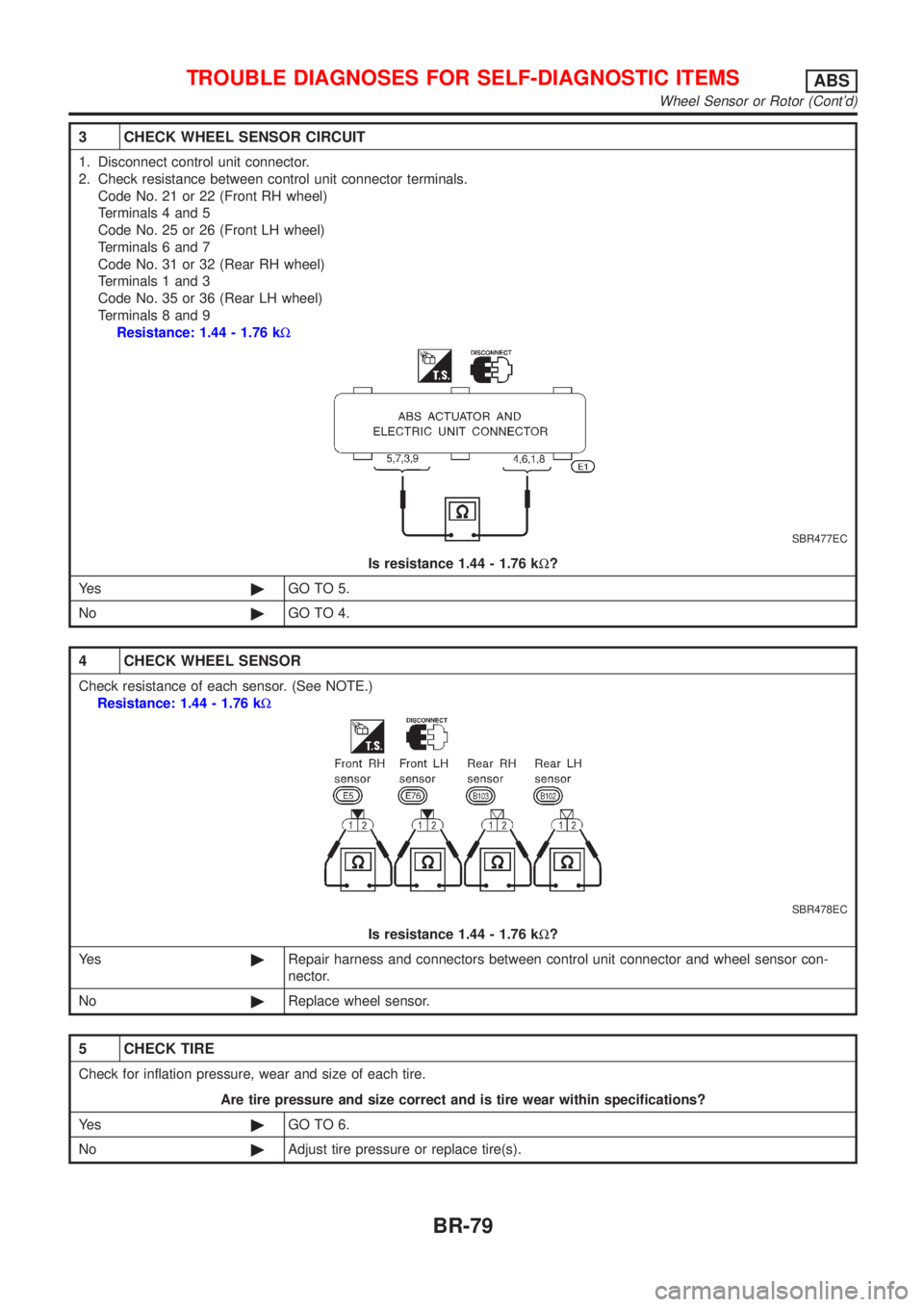
3 CHECK WHEEL SENSOR CIRCUIT
1. Disconnect control unit connector.
2. Check resistance between control unit connector terminals.
Code No. 21 or 22 (Front RH wheel)
Terminals 4 and 5
Code No. 25 or 26 (Front LH wheel)
Terminals 6 and 7
Code No. 31 or 32 (Rear RH wheel)
Terminals 1 and 3
Code No. 35 or 36 (Rear LH wheel)
Terminals 8 and 9
Resistance: 1.44 - 1.76 kW
SBR477EC
Is resistance 1.44 - 1.76 kW?
Ye s©GO TO 5.
No©GO TO 4.
4 CHECK WHEEL SENSOR
Check resistance of each sensor. (See NOTE.)
Resistance: 1.44 - 1.76 kW
SBR478EC
Is resistance 1.44 - 1.76 kW?
Ye s©Repair harness and connectors between control unit connector and wheel sensor con-
nector.
No©Replace wheel sensor.
5 CHECK TIRE
Check for inflation pressure, wear and size of each tire.
Are tire pressure and size correct and is tire wear within specifications?
Ye s©GO TO 6.
No©Adjust tire pressure or replace tire(s).
TROUBLE DIAGNOSES FOR SELF-DIAGNOSTIC ITEMSABS
Wheel Sensor or Rotor (Cont'd)
BR-79
Page 2136 of 2898
REPLACEMENT OF CONNECTING ROD
BUSHING (SMALL END)
..........................................62
FLYWHEEL/DRIVE PLATE RUNOUT........................62
Assembly ...................................................................62
PISTON..................................................................62
CRANKSHAFT.........................................................63
SERVICE DATA AND SPECIFICATIONS (SDS).........66
General Specifications ...............................................66
Compression Pressure ..............................................66
Belt Deflection............................................................67
Spark Plug .................................................................67
Cylinder Head ............................................................67
Valve ..........................................................................68
VALVE....................................................................68
VALVE SPRING.......................................................68
VALVE LIFTER........................................................68
VALVE CLEARANCE................................................69
VALVE GUIDE.........................................................69
AVAILABLE SHIMS..................................................69
VALVE SEAT...........................................................71
VALVE SEAT RESURFACE LIMIT.............................72
Camshaft and Camshaft Bearing ..............................72
Cylinder Block ............................................................73
Piston, Piston Ring and Piston Pin ...........................74
PISTON..................................................................74
PISTON RING.........................................................74
PISTON PIN............................................................74
Connecting Rod .........................................................75
Crankshaft..................................................................75
Main Bearing..............................................................75
STANDARD.............................................................75
UNDERSIZE............................................................75
Connecting Rod Bearing ...........................................76
STANDARD SIZE....................................................76
UNDERSIZE............................................................76
Bearing Clearance .....................................................76
Miscellaneous Components.......................................76
YD
PRECAUTIONS.............................................................77
Parts Requiring Angular Tightening ...........................77
Liquid Gasket Application Procedure ........................77
PREPARATION.............................................................78
Special Service Tools ................................................78
Commercial Service Tools .........................................80
NOISE, VIBRATION AND HARSHNESS (NVH)
TROUBLESHOOTING...................................................82
NVH Troubleshooting - Engine Noise .......................82
MEASUREMENT OF COMPRESSION PRESSURE....83
DRIVE BELTS................................................................85
Inspection...................................................................85
Adjustment .................................................................85
AIR CONDITIONER COMPRESSOR BELT................86
ALTERNATOR & WATER PUMP BELT.....................86
Removal .....................................................................86
Installation ..................................................................87
AIR CLEANER...............................................................88
Changing Air Cleaner Filter .......................................88
VISCOUS PAPER TYPE...........................................88
OIL PAN.........................................................................89
Components...............................................................89
Removal .....................................................................89
Installation ..................................................................91
TIMING CHAIN..............................................................94
Secondary Timing Chain ...........................................94
REMOVAL...............................................................94
INSPECTION...........................................................96
INSTALLATION........................................................96
Primary Timing Chain ................................................99
REMOVAL.............................................................100
INSPECTION.........................................................102
INSTALLATION......................................................102
INTAKE MANIFOLD....................................................107
Removal and Installation .........................................107
PREPARATIVE WORK...........................................107
FUEL PIPING........................................................108
INTAKE MANIFOLD...............................................108
EGR VOLUME CONTROL VALVE...........................108
WATER HOSE.......................................................108
Inspection.................................................................109
INTAKE MANIFOLD...............................................109
CATALYST.................................................................. 110
Removal and Installation ......................................... 110
PREPARATIVE WORK........................................... 110
CATALYST............................................................ 110
GUSSET............................................................... 111
EXHAUST MANIFOLD, TURBOCHARGER............... 112
Removal and Installation ......................................... 112
PREPARATIVE WORK........................................... 112
EXHAUST MANIFOLD AND TURBOCHARGER....... 112
EXHAUST MANIFOLD GASKET............................. 113
Disassembly and Assembly ..................................... 113
TURBOCHARGER................................................. 113
Inspection................................................................. 114
EXHAUST MANIFOLD........................................... 114
TURBOCHARGER................................................. 114
ROCKER COVER........................................................ 117
Removal and Installation ......................................... 117
PREPARATIVE WORK........................................... 117
ROCKER COVER.................................................. 117
CYLINDER HEAD........................................................ 119
Components............................................................. 119
Removal ...................................................................120
PREPARATIVE WORK...........................................120
CAMSHAFT...........................................................120
CYLINDER HEAD..................................................121
Disassembly.............................................................121
Inspection.................................................................122
CONTENTS(Cont'd)
EM-2
Page 2137 of 2898
CYLINDER HEAD DISTORTION.............................122
CAMSHAFT VISUAL CHECK..................................123
CAMSHAFT RUNOUT............................................123
CAMSHAFT CAM HEIGHT.....................................123
CAMSHAFT JOURNAL CLEARANCE......................123
CAMSHAFT END PLAY..........................................124
CAMSHAFT SPROCKET RUNOUT.........................124
VALVE GUIDE CLEARANCE..................................124
VALVE GUIDE REPLACEMENT..............................125
VALVE SEATS.......................................................126
REPLACING VALVE SEAT FOR SERVICE PARTS..126
VALVE DIMENSIONS.............................................128
VALVE SPRING.....................................................128
VALVE LIFTER......................................................128
Assembly .................................................................129
Installation ................................................................129
CYLINDER HEAD GASKET SELECTION.................130
CYLINDER HEAD BOLT DEFORMATION CHECK...131
CYLINDER HEAD-TO-BLOCK DIFFERENCE
CHECK
.................................................................131
LIQUID GASKET APPLICATION ON REAR CHAIN
CASE
....................................................................131
CYLINDER HEAD INSTALLATION..........................132
GLOW PLUG INSTALLATION.................................132
CAMSHAFT INSTALLATION...................................132
Valve Clearance.......................................................133
CHECKING...........................................................133
ADJUSTING..........................................................134
ENGINE ASSEMBLY...................................................137
Removal and Installation .........................................137
REMOVAL.............................................................138
INSTALLATION......................................................139
CYLINDER BLOCK.....................................................140
Components.............................................................140
Removal and Installation .........................................141
Disassembly.............................................................141
PISTON AND CRANKSHAFT..................................141
Inspection.................................................................144
CRANKSHAFT END PLAY.....................................144
CONNECTING ROD SIDE CLEARANCE.................144
PISTON AND PISTON PIN CLEARANCE................145
PISTON RING SIDE CLEARANCE..........................145
PISTON RING END GAP........................................145
CONNECTING ROD BEND AND TORSION.............146
CYLINDER BLOCK DISTORTION AND WEAR.........146
PISTON-TO-BORE CLEARANCE............................147
CRANKSHAFT.......................................................148
MAIN BEARING HOUSING INNER DIAMETER........149
BEARING CLEARANCE.........................................149
MAIN BEARING CRUSH HEIGHT...........................153
MAIN BEARING CAP BOLT DEFORMATION...........153
CONNECTING ROD BUSHING CLEARANCE
(SMALL END)
........................................................153
CONNECTING ROD BOLT DEFORMATION............154
FLYWHEEL RUNOUT............................................154
OIL JET................................................................154
OIL JET RELIEF VALVE.........................................154
Assembly .................................................................155
PISTON................................................................155
CRANKSHAFT.......................................................155
REPLACEMENT OF PILOT BUSHING.....................158
SERVICE DATA AND SPECIFICATIONS (SDS).......160
General Specifications .............................................160
Compression Pressure ............................................160
Belt Deflection..........................................................160
Cylinder Head ..........................................................160
Valve ........................................................................161
VALVE..................................................................161
VALVE CLEARANCE..............................................161
AVAILABLE SHIMS................................................161
VALVE SPRING.....................................................162
VALVE LIFTER......................................................162
VALVE GUIDE.......................................................163
Valve Seat................................................................164
Camshaft and Camshaft Bearing ............................166
Cylinder Block ..........................................................167
Piston, Piston Ring and Piston Pin .........................167
AVAILABLE PISTON..............................................167
PISTON RING.......................................................168
PISTON PIN..........................................................168
Connecting Rod .......................................................168
Crankshaft................................................................168
Available Main Bearing ............................................169
UNDERSIZE..........................................................169
Available Connecting Rod Bearing..........................169
CONNECTING ROD BEARING...............................169
UNDERSIZE..........................................................170
Miscellaneous Components.....................................170
BEARING CLEARANCE.........................................170
CONTENTS(Cont'd)
EM-3
Page 2210 of 2898
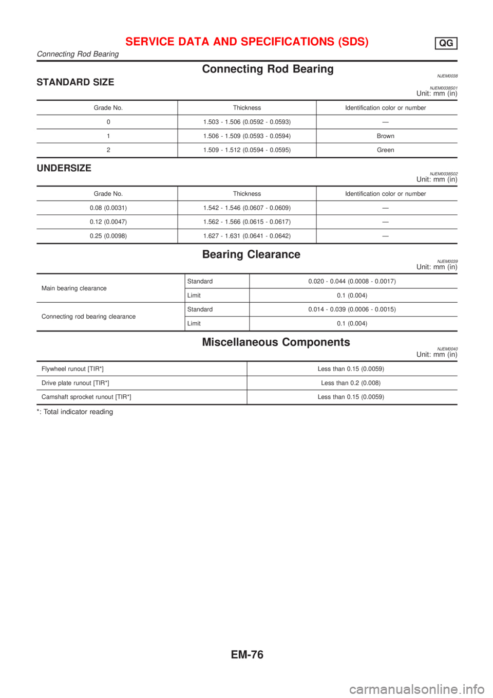
Connecting Rod BearingNJEM0038STANDARD SIZENJEM0038S01Unit: mm (in)
Grade No. Thickness Identification color or number
0 1.503 - 1.506 (0.0592 - 0.0593) Ð
1 1.506 - 1.509 (0.0593 - 0.0594) Brown
2 1.509 - 1.512 (0.0594 - 0.0595) Green
UNDERSIZENJEM0038S02Unit: mm (in)
Grade No. Thickness Identification color or number
0.08 (0.0031) 1.542 - 1.546 (0.0607 - 0.0609) Ð
0.12 (0.0047) 1.562 - 1.566 (0.0615 - 0.0617) Ð
0.25 (0.0098) 1.627 - 1.631 (0.0641 - 0.0642) Ð
Bearing ClearanceNJEM0039Unit: mm (in)
Main bearing clearanceStandard 0.020 - 0.044 (0.0008 - 0.0017)
Limit 0.1 (0.004)
Connecting rod bearing clearanceStandard 0.014 - 0.039 (0.0006 - 0.0015)
Limit 0.1 (0.004)
Miscellaneous ComponentsNJEM0040Unit: mm (in)
Flywheel runout [TIR*]Less than 0.15 (0.0059)
Drive plate runout [TIR*]Less than 0.2 (0.008)
Camshaft sprocket runout [TIR*] Less than 0.15 (0.0059)
*: Total indicator reading
SERVICE DATA AND SPECIFICATIONS (SDS)QG
Connecting Rod Bearing
EM-76
Page 2275 of 2898
Removal and InstallationNJEM0071CAUTION:
+When installing bearings, pistons, or other sliding parts,
lubricate contacting surfaces with new engine oil.
+Place removed parts such as bearings and bearing caps
in their proper order and direction.
+When installing connecting rod nuts, and main bearing
cap bolts, apply new engine oil to threads and seating
surfaces.
+Do not allow any magnetic materials to contact the signal
plate of flywheel.
+Do not remove the signal plate at back.
+Do not place the signal plate side facing under.
+Handle with care so as not to damage the signal plate
[especially four places on protrusions for signal of crank
position sensor (TDC sensor)].
DisassemblyNJEM0072PISTON AND CRANKSHAFTNJEM0072S011. Remove engine. Refer to ªENGINE ASSEMBLYº, ªRemoval
and Installationº, EM-137.
2. Place engine on a work stand.
a. Remove flywheel.
+Hold ring gear with ring gear stopper (KV10105630,
KV10105610). Then, loosen securing bolts with TORX socket
(size: Q8 E20, Commercial Service Tool) and remove them.
As an alternative method, hold the crankshaft pulley with a
pulley holder (SST) to remove the flywheel.
JEM192G
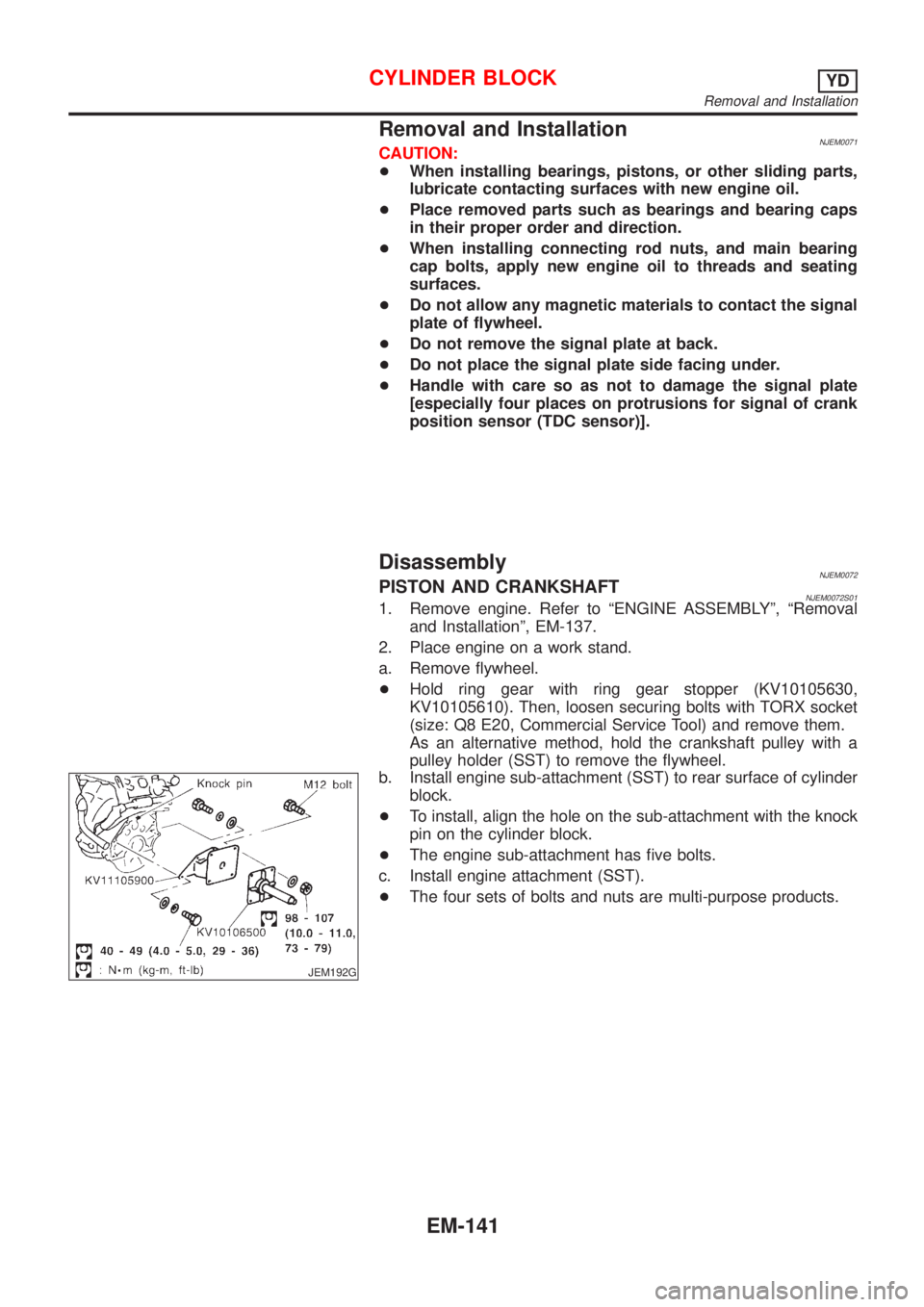
b. Install engine sub-attachment (SST) to rear surface of cylinder
block.
+To install, align the hole on the sub-attachment with the knock
pin on the cylinder block.
+The engine sub-attachment has five bolts.
c. Install engine attachment (SST).
+The four sets of bolts and nuts are multi-purpose products.
CYLINDER BLOCKYD
Removal and Installation
EM-141
Page 2292 of 2898
JEM233G
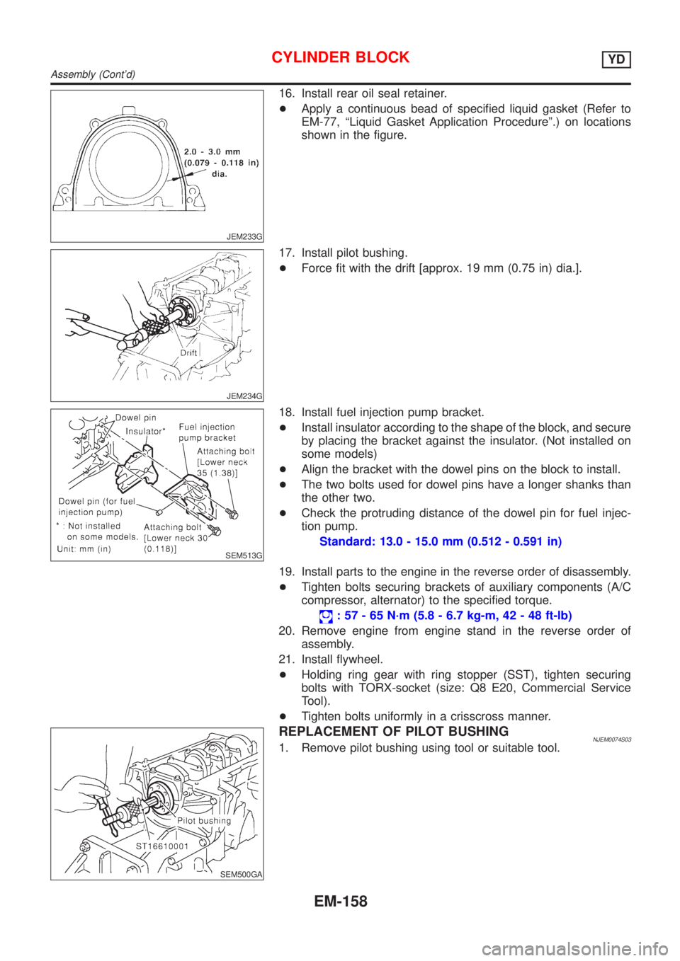
16. Install rear oil seal retainer.
+Apply a continuous bead of specified liquid gasket (Refer to
EM-77, ªLiquid Gasket Application Procedureº.) on locations
shown in the figure.
JEM234G
17. Install pilot bushing.
+Force fit with the drift [approx. 19 mm (0.75 in) dia.].
SEM513G
18. Install fuel injection pump bracket.
+Install insulator according to the shape of the block, and secure
by placing the bracket against the insulator. (Not installed on
some models)
+Align the bracket with the dowel pins on the block to install.
+The two bolts used for dowel pins have a longer shanks than
the other two.
+Check the protruding distance of the dowel pin for fuel injec-
tion pump.
Standard: 13.0 - 15.0 mm (0.512 - 0.591 in)
19. Install parts to the engine in the reverse order of disassembly.
+Tighten bolts securing brackets of auxiliary components (A/C
compressor, alternator) to the specified torque.
: 57 - 65 N´m (5.8 - 6.7 kg-m, 42 - 48 ft-lb)
20. Remove engine from engine stand in the reverse order of
assembly.
21. Install flywheel.
+Holding ring gear with ring stopper (SST), tighten securing
bolts with TORX-socket (size: Q8 E20, Commercial Service
Tool).
+Tighten bolts uniformly in a crisscross manner.
SEM500GA
REPLACEMENT OF PILOT BUSHINGNJEM0074S031. Remove pilot bushing using tool or suitable tool.
CYLINDER BLOCKYD
Assembly (Cont'd)
EM-158
Page 2304 of 2898
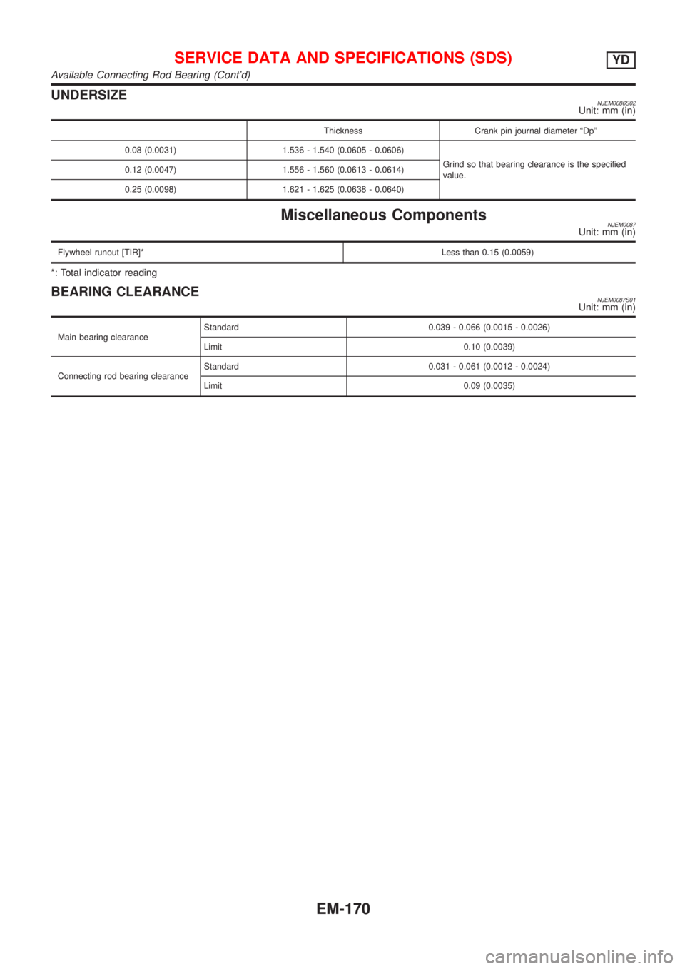
UNDERSIZENJEM0086S02Unit: mm (in)
Thickness Crank pin journal diameter ªDpº
0.08 (0.0031) 1.536 - 1.540 (0.0605 - 0.0606)
Grind so that bearing clearance is the specified
value. 0.12 (0.0047) 1.556 - 1.560 (0.0613 - 0.0614)
0.25 (0.0098) 1.621 - 1.625 (0.0638 - 0.0640)
Miscellaneous ComponentsNJEM0087Unit: mm (in)
Flywheel runout [TIR]*Less than 0.15 (0.0059)
*: Total indicator reading
BEARING CLEARANCENJEM0087S01Unit: mm (in)
Main bearing clearanceStandard 0.039 - 0.066 (0.0015 - 0.0026)
Limit 0.10 (0.0039)
Connecting rod bearing clearanceStandard 0.031 - 0.061 (0.0012 - 0.0024)
Limit 0.09 (0.0035)
SERVICE DATA AND SPECIFICATIONS (SDS)YD
Available Connecting Rod Bearing (Cont'd)
EM-170
Page 2389 of 2898
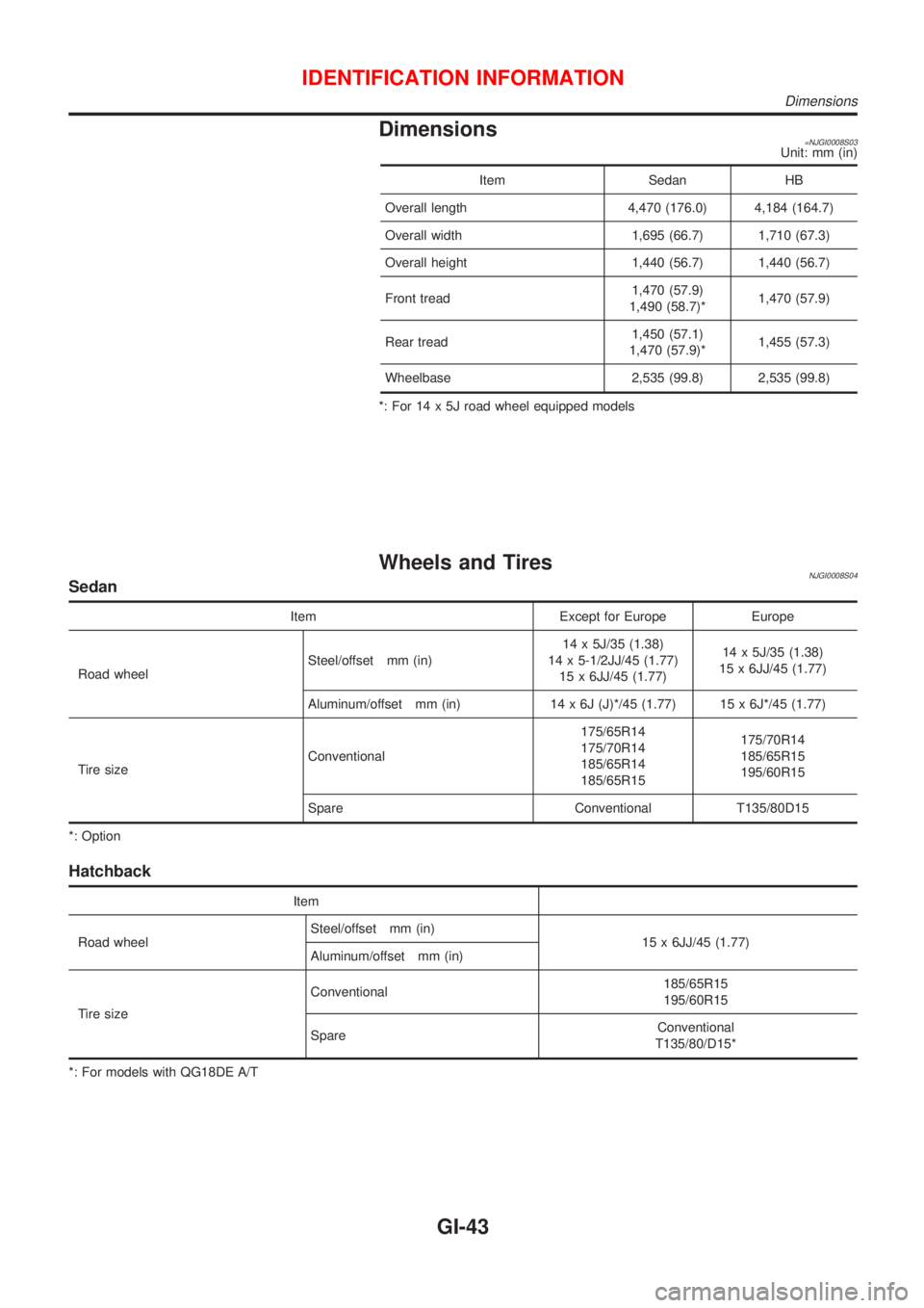
Dimensions=NJGI0008S03Unit: mm (in)
Item Sedan HB
Overall length 4,470 (176.0) 4,184 (164.7)
Overall width 1,695 (66.7) 1,710 (67.3)
Overall height 1,440 (56.7) 1,440 (56.7)
Front tread1,470 (57.9)
1,490 (58.7)*1,470 (57.9)
Rear tread1,450 (57.1)
1,470 (57.9)*1,455 (57.3)
Wheelbase 2,535 (99.8) 2,535 (99.8)
*: For 14 x 5J road wheel equipped models
Wheels and TiresNJGI0008S04Sedan
Item Except for Europe Europe
Road wheelSteel/offset mm (in)14 x 5J/35 (1.38)
14 x 5-1/2JJ/45 (1.77)
15 x 6JJ/45 (1.77)14 x 5J/35 (1.38)
15 x 6JJ/45 (1.77)
Aluminum/offset mm (in) 14 x 6J (J)*/45 (1.77) 15 x 6J*/45 (1.77)
Tire sizeConventional175/65R14
175/70R14
185/65R14
185/65R15175/70R14
185/65R15
195/60R15
Spare Conventional T135/80D15
*: Option
Hatchback
Item
Road wheelSteel/offset mm (in)
15 x 6JJ/45 (1.77)
Aluminum/offset mm (in)
Tire sizeConventional185/65R15
195/60R15
SpareConventional
T135/80/D15*
*: For models with QG18DE A/T
IDENTIFICATION INFORMATION
Dimensions
GI-43