Page 539 of 2898
RemovalNJBR0123
SBR631E
1. Remove parts shown below.
+Air duct, air cleaner case (upper)
+Engine cover
+Rocker cover
+Exhaust manifold cover
+EGR tube
2. Disconnect vacuum hose from vacuum pump.
3. Remove cylinder head rear cover plate.
+Use a tool such as seal cutter (SST) to remove.
4. Loosen and remove rear cam sprocket installation bolts.
+Camshaft should not be attached. Using engine inner
resistance, loosen installation bolts.
SBR632E
5. Remove vacuum pump and cylinder head rear cover assem-
bly.
+Remove and install vacuum pump, sprocket, drive chain, and
chain guide as an assembly.
+Loosen mounting bolts in the reverse order of the numbers
shown in the figure to the left.
+Remove only bolts that are shown in the figure. (Be especially
careful not to remove M6 bolts on the vacuum pump.)
+Use a tool such as a seal cutter (SST).
VACUUM PUMP
Removal
BR-23
Page 540 of 2898
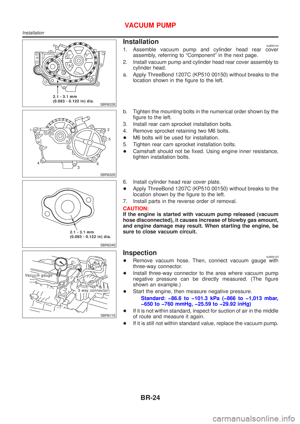
SBR633E
InstallationNJBR01241. Assemble vacuum pump and cylinder head rear cover
assembly, referring to ªComponentº in the next page.
2. Install vacuum pump and cylinder head rear cover assembly to
cylinder head.
a. Apply ThreeBond 1207C (KP510 00150) without breaks to the
location shown in the figure to the left.
SBR632E
b. Tighten the mounting bolts in the numerical order shown by the
figure to the left.
3. Install rear cam sprocket installation bolts.
4. Remove sprocket retaining two M6 bolts.
+M6 bolts will be used for installation.
5. Tighten rear cam sprocket installation bolts.
+Camshaft should not be fixed. Using engine inner resistance,
tighten installation bolts.
SBR634E
6. Install cylinder head rear cover plate.
+Apply ThreeBond 1207C (KP510 00150) without breaks to the
location shown by the figure to the left.
7. Install parts in the reverse order of removal.
CAUTION:
If the engine is started with vacuum pump released (vacuum
hose disconnected), it causes increase of blowby gas amount,
and engine damage may result. When starting the engine, be
sure to close vacuum circuit.
SBR611E
InspectionNJBR0125+Remove vacuum hose. Then, connect vacuum gauge with
three-way connector.
+Install three-way connector to the area where vacuum pump
negative pressure can be directly measured. (The figure
shown an example.)
+Start the engine, then measure negative pressure.
Standard: þ86.6 to þ101.3 kPa (þ866 to þ1,013 mbar,
þ650 to þ760 mmHg, þ25.59 to þ29.92 inHg)
+If it is not within standard, inspect for suction of air in the middle
of route and measure it again.
+If it is still not within standard value, replace the vacuum pump.
VACUUM PUMP
Installation
BR-24
Page 541 of 2898
ComponentNJBR0126
SBR612E
SBR613E
DisassemblyNJBR0136Disassemble the components, referring to the ªComponentº, then
remove vacuum pump.
CAUTION:
Do not disassemble vacuum pump. (Do not loosen three M6
bolts.)
AssemblyNJBR0127Install all parts to cylinder head rear cover as follows.
1. Install vacuum pump.
2. Install chain guide temporarily.
+Adjust the chain guide position by the method explained in step
5.
SBR614E
3. Install rear cam sprocket.
+Installation direction of sprocket is not specified.
+Insert 2 thickness gauges [3.0 mm (0.118 in)] between cover
and rear cam sprocket (shown in the figure). Insert 2 bolts [M6,
thread length: 35 - 40 mm (1.38 - 1.57 in)] into sprocket to
retain it to cover.
+Use thickness gauges [3.0 mm (0.118 in)] for chain alignment
between vacuum pump sprocket and cam sprocket.
4. Attach drive chain to rear cam sprocket and vacuum pump
sprocket.
5. Tighten chain guide installation bolt while pressing chain guide
VACUUM PUMP
Component
BR-25
Page 724 of 2898
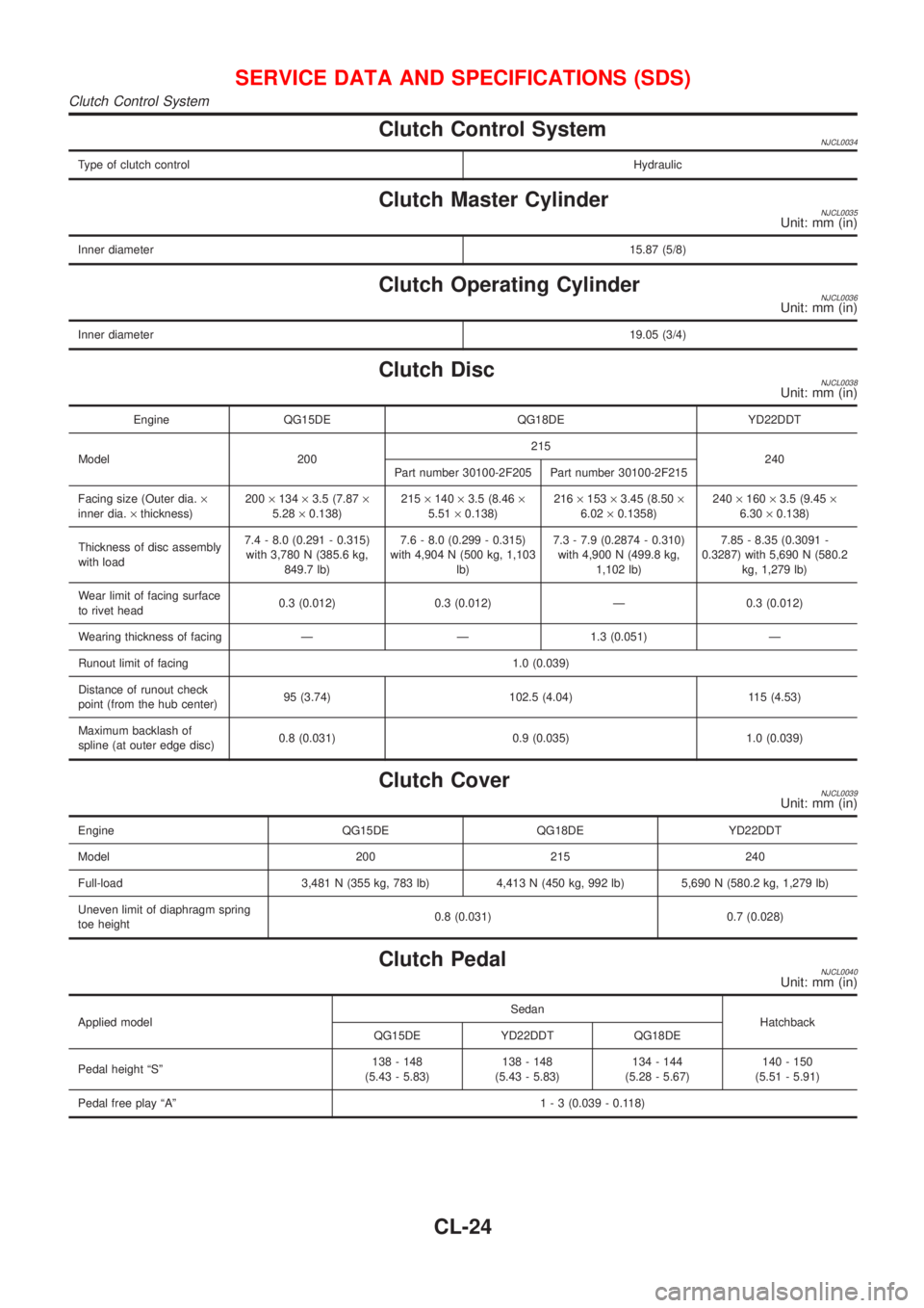
Clutch Control SystemNJCL0034
Type of clutch controlHydraulic
Clutch Master CylinderNJCL0035Unit: mm (in)
Inner diameter15.87 (5/8)
Clutch Operating CylinderNJCL0036Unit: mm (in)
Inner diameter19.05 (3/4)
Clutch DiscNJCL0038Unit: mm (in)
Engine QG15DE QG18DE YD22DDT
Model 200215
240
Part number 30100-2F205 Part number 30100-2F215
Facing size (Outer dia.´
inner dia.´thickness)200´134´3.5 (7.87´
5.28´0.138)215´140´3.5 (8.46´
5.51´0.138)216´153´3.45 (8.50´
6.02´0.1358)240´160´3.5 (9.45´
6.30´0.138)
Thickness of disc assembly
with load7.4 - 8.0 (0.291 - 0.315)
with 3,780 N (385.6 kg,
849.7 lb)7.6 - 8.0 (0.299 - 0.315)
with 4,904 N (500 kg, 1,103
lb)7.3 - 7.9 (0.2874 - 0.310)
with 4,900 N (499.8 kg,
1,102 lb)7.85 - 8.35 (0.3091 -
0.3287) with 5,690 N (580.2
kg, 1,279 lb)
Wear limit of facing surface
to rivet head0.3 (0.012) 0.3 (0.012) Ð 0.3 (0.012)
Wearing thickness of facing Ð Ð 1.3 (0.051) Ð
Runout limit of facing 1.0 (0.039)
Distance of runout check
point (from the hub center)95 (3.74) 102.5 (4.04) 115 (4.53)
Maximum backlash of
spline (at outer edge disc)0.8 (0.031) 0.9 (0.035) 1.0 (0.039)
Clutch CoverNJCL0039Unit: mm (in)
Engine QG15DE QG18DE YD22DDT
Model 200 215 240
Full-load 3,481 N (355 kg, 783 lb) 4,413 N (450 kg, 992 lb) 5,690 N (580.2 kg, 1,279 lb)
Uneven limit of diaphragm spring
toe height0.8 (0.031) 0.7 (0.028)
Clutch PedalNJCL0040Unit: mm (in)
Applied modelSedan
Hatchback
QG15DE YD22DDT QG18DE
Pedal height ªSº138 - 148
(5.43 - 5.83)138 - 148
(5.43 - 5.83)134 - 144
(5.28 - 5.67)140 - 150
(5.51 - 5.91)
Pedal free play ªAº1 - 3 (0.039 - 0.118)
SERVICE DATA AND SPECIFICATIONS (SDS)
Clutch Control System
CL-24
Page 882 of 2898
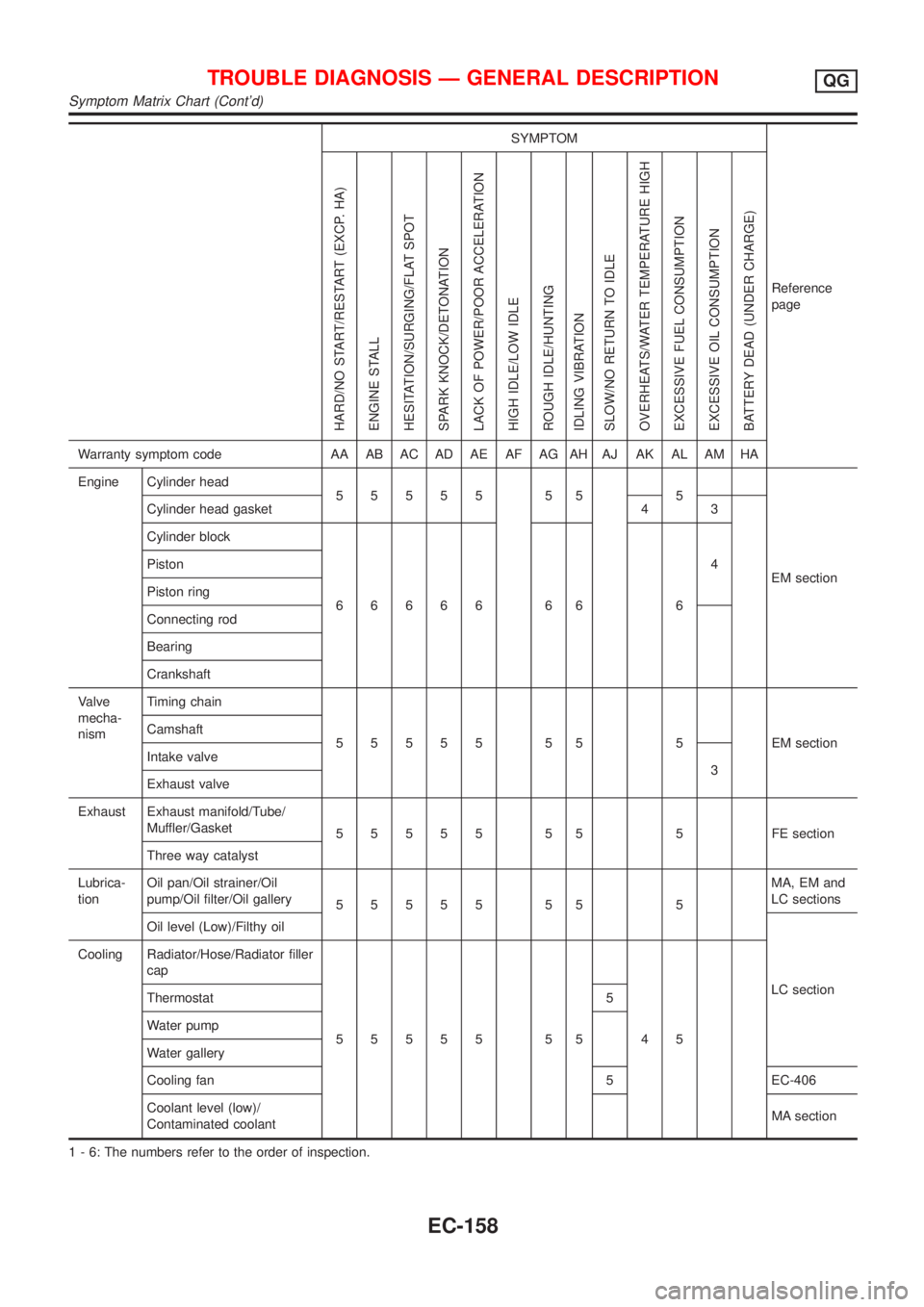
SYMPTOM
Reference
page
HARD/NO START/RESTART (EXCP. HA)
ENGINE STALL
HESITATION/SURGING/FLAT SPOT
SPARK KNOCK/DETONATION
LACK OF POWER/POOR ACCELERATION
HIGH IDLE/LOW IDLE
ROUGH IDLE/HUNTING
IDLING VIBRATION
SLOW/NO RETURN TO IDLE
OVERHEATS/WATER TEMPERATURE HIGH
EXCESSIVE FUEL CONSUMPTION
EXCESSIVE OIL CONSUMPTION
BATTERY DEAD (UNDER CHARGE)
Warranty symptom code AA AB AC AD AE AF AG AH AJ AK AL AM HA
Engine Cylinder head
55555 55 5
EM section Cylinder head gasket 4 3
Cylinder block
66666 66 64 Piston
Piston ring
Connecting rod
Bearing
Crankshaft
Valve
mecha-
nismTiming chain
55555 55 5 EMsection Camshaft
Intake valve
3
Exhaust valve
Exhaust Exhaust manifold/Tube/
Muffler/Gasket
55555 55 5 FEsection
Three way catalyst
Lubrica-
tionOil pan/Oil strainer/Oil
pump/Oil filter/Oil gallery
55555 55 5MA, EM and
LC sections
Oil level (Low)/Filthy oil
LC section Cooling Radiator/Hose/Radiator filler
cap
55555 55 45 Thermostat 5
Water pump
Water gallery
Cooling fan 5 EC-406
Coolant level (low)/
Contaminated coolantMA section
1 - 6: The numbers refer to the order of inspection.
TROUBLE DIAGNOSIS Ð GENERAL DESCRIPTIONQG
Symptom Matrix Chart (Cont'd)
EC-158
Page 1045 of 2898
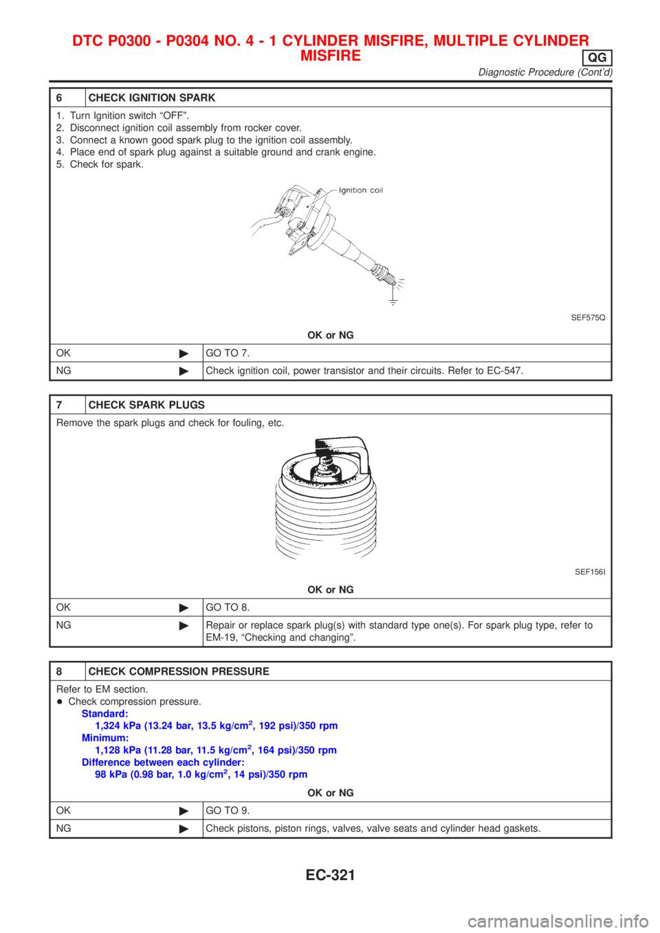
6 CHECK IGNITION SPARK
1. Turn Ignition switch ªOFFº.
2. Disconnect ignition coil assembly from rocker cover.
3. Connect a known good spark plug to the ignition coil assembly.
4. Place end of spark plug against a suitable ground and crank engine.
5. Check for spark.
SEF575Q
OK or NG
OK©GO TO 7.
NG©Check ignition coil, power transistor and their circuits. Refer to EC-547.
7 CHECK SPARK PLUGS
Remove the spark plugs and check for fouling, etc.
SEF156I
OK or NG
OK©GO TO 8.
NG©Repair or replace spark plug(s) with standard type one(s). For spark plug type, refer to
EM-19, ªChecking and changingº.
8 CHECK COMPRESSION PRESSURE
Refer to EM section.
+Check compression pressure.
Standard:
1,324 kPa (13.24 bar, 13.5 kg/cm
2, 192 psi)/350 rpm
Minimum:
1,128 kPa (11.28 bar, 11.5 kg/cm
2, 164 psi)/350 rpm
Difference between each cylinder:
98 kPa (0.98 bar, 1.0 kg/cm
2, 14 psi)/350 rpm
OK or NG
OK©GO TO 9.
NG©Check pistons, piston rings, valves, valve seats and cylinder head gaskets.
DTC P0300 - P0304 NO.4-1CYLINDER MISFIRE, MULTIPLE CYLINDER
MISFIRE
QG
Diagnostic Procedure (Cont'd)
EC-321
Page 1075 of 2898
SEF069X
SEF605Y
SEF015Y
SEF560W
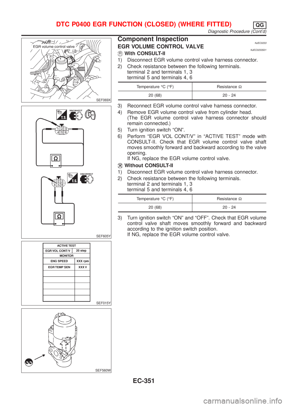
Component InspectionNJEC0233EGR VOLUME CONTROL VALVENJEC0233S01With CONSULT-II
1) Disconnect EGR volume control valve harness connector.
2) Check resistance between the following terminals.
terminal 2 and terminals 1, 3
terminal 5 and terminals 4, 6
Temperature ÉC (ÉF) ResistanceW
20 (68) 20 - 24
3) Reconnect EGR volume control valve harness connector.
4) Remove EGR volume control valve from cylinder head.
(The EGR volume control valve harness connector should
remain connected.)
5) Turn ignition switch ªONº.
6) Perform ªEGR VOL CONT/Vº in ªACTIVE TESTº mode with
CONSULT-II. Check that EGR volume control valve shaft
moves smoothly forward and backward according to the valve
opening.
If NG, replace the EGR volume control valve.
Without CONSULT-II
1) Disconnect EGR volume control valve harness connector.
2) Check resistance between the following terminals.
terminal 2 and terminals 1, 3
terminal 5 and terminals 4, 6
Temperature ÉC (ÉF) ResistanceW
20 (68) 20 - 24
3) Turn ignition switch ªONº and ªOFFº. Check that EGR volume
control valve shaft moves smoothly forward and backward
according to the ignition switch position.
If NG, replace the EGR volume control valve.
DTC P0400 EGR FUNCTION (CLOSED) (WHERE FITTED)QG
Diagnostic Procedure (Cont'd)
EC-351
Page 1082 of 2898
SEF069X
SEF605Y
SEF015Y
SEF560W
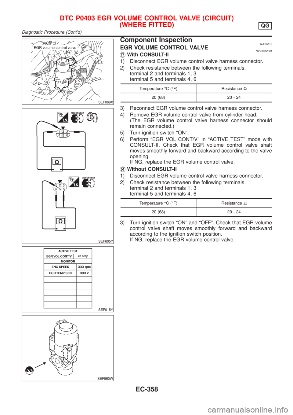
Component InspectionNJEC0512EGR VOLUME CONTROL VALVENJEC0512S01With CONSULT-II
1) Disconnect EGR volume control valve harness connector.
2) Check resistance between the following terminals.
terminal 2 and terminals 1, 3
terminal 5 and terminals 4, 6
Temperature ÉC (ÉF) ResistanceW
20 (68) 20 - 24
3) Reconnect EGR volume control valve harness connector.
4) Remove EGR volume control valve from cylinder head.
(The EGR volume control valve harness connector should
remain connected.)
5) Turn ignition switch ªONº.
6) Perform ªEGR VOL CONT/Vº in ªACTIVE TESTº mode with
CONSULT-II. Check that EGR volume control valve shaft
moves smoothly forward and backward according to the valve
opening.
If NG, replace the EGR volume control valve.
Without CONSULT-II
1) Disconnect EGR volume control valve harness connector.
2) Check resistance between the following terminals.
terminal 2 and terminals 1, 3
terminal 5 and terminals 4, 6
Temperature ÉC (ÉF) ResistanceW
20 (68) 20 - 24
3) Turn ignition switch ªONº and ªOFFº. Check that EGR volume
control valve shaft moves smoothly forward and backward
according to the ignition switch position.
If NG, replace the EGR volume control valve.
DTC P0403 EGR VOLUME CONTROL VALVE (CIRCUIT)
(WHERE FITTED)
QG
Diagnostic Procedure (Cont'd)
EC-358