2001 NISSAN ALMERA Cylinder head
[x] Cancel search: Cylinder headPage 1140 of 2898
Main 12 Causes of Overheating=NJEC0492
Engine Step Inspection item Equipment Standard Reference page
OFF 1+Blocked radiator
+Blocked condenser
+Blocked radiator grille
+Blocked bumper+Visual No blocking Ð
2+Coolant mixture+Coolant tester 50 - 50% coolant mixture See MA-16, ªRECOM-
MENDED FLUIDS AND
LUBRICANTSº.
3+Coolant level+Visual Coolant up to MAX level
in reservoir tank and
radiator filler neckSee LC-18, ªChanging
Engine Coolantº.
4+Radiator cap+Pressure tester 59 - 98 kPa
(0.59 - 0.98 bar, 0.6 - 1.0
kg/cm
2,9-14psi) (Limit)See LC-10, ªSystem
Checkº.
ON*
25+Coolant leaks+Visual No leaks See LC-10, ªSystem
Checkº.
ON*
26+Thermostat+Touch the upper and
lower radiator hosesBoth hoses should be
hotSee LC-15, ªThermostatº
and LC-16, ªRadiatorº.
ON*
17+Cooling fan+CONSULT-II Operating See ªTROUBLE DIAG-
NOSIS FOR OVER-
HEATº (EC-406).
OFF 8+Combustion gas leak+Color checker chemi-
cal tester 4 Gas ana-
lyzerNegative Ð
ON*
39+Coolant temperature
gauge+Visual Gauge less than 3/4
when drivingÐ
+Coolant overflow to
reservoir tank+Visual No overflow during driv-
ing and idlingSee LC-18, ªChanging
Engine Coolantº.
OFF*
410+Coolant return from
reservoir tank to radia-
tor+Visual Should be initial level in
reservoir tankSee LC-19, ªRefilling
Engine Coolantº.
OFF 11+Cylinder head+Straight gauge feeler
gauge0.1 mm (0.004 in) Maxi-
mum distortion (warping)See EM-37, ªInspectionº,
ªCYLINDER HEADº.
12+Cylinder block and
pistons+Visual No scuffing on cylinder
walls or pistonSee EM-56, ªInspectionº,
ªCYLINDER BLOCKº.
*1: Turn the ignition switch ON.
*2: Engine running at 3,000 rpm for 10 minutes.
*3: Drive at 90 km/h (55 MPH) for 30 minutes and then let idle for 10 minutes.
*4: After 60 minutes of cool down time.
For more information, refer to LC-24, ª OVERHEATING CAUSE ANALYSISº.
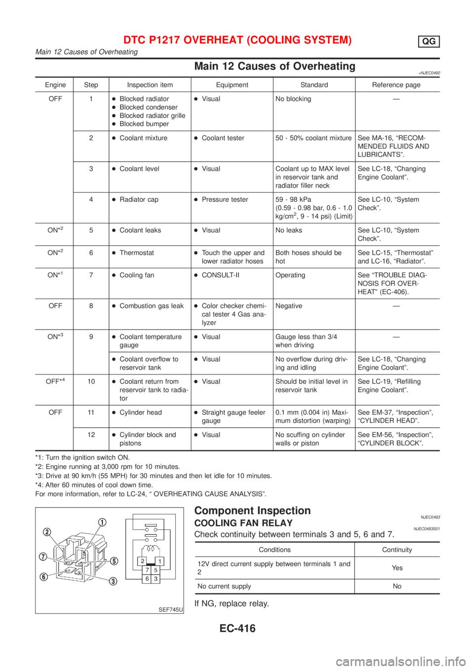
SEF745U
Component InspectionNJEC0493COOLING FAN RELAYNJEC0493S01Check continuity between terminals 3 and 5, 6 and 7.
Conditions Continuity
12V direct current supply between terminals 1 and
2Ye s
No current supply No
If NG, replace relay.
DTC P1217 OVERHEAT (COOLING SYSTEM)QG
Main 12 Causes of Overheating
EC-416
Page 1157 of 2898
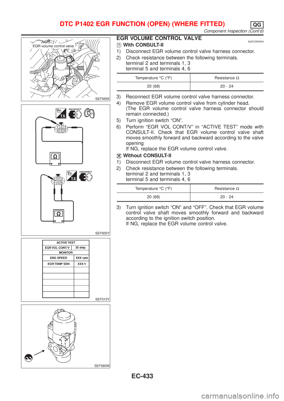
SEF069X
SEF605Y
SEF015Y
SEF560W
EGR VOLUME CONTROL VALVENJEC0354S04With CONSULT-II
1) Disconnect EGR volume control valve harness connector.
2) Check resistance between the following terminals.
terminal 2 and terminals 1, 3
terminal 5 and terminals 4, 6
Temperature ÉC (ÉF) ResistanceW
20 (68) 20 - 24
3) Reconnect EGR volume control valve harness connector.
4) Remove EGR volume control valve from cylinder head.
(The EGR volume control valve harness connector should
remain connected.)
5) Turn ignition switch ªONº.
6) Perform ªEGR VOL CONT/Vº in ªACTIVE TESTº mode with
CONSULT-II. Check that EGR volume control valve shaft
moves smoothly forward and backward according to the valve
opening
If NG, replace the EGR volume control valve.
Without CONSULT-II
1) Disconnect EGR volume control valve harness connector.
2) Check resistance between the following terminals.
terminal 2 and terminals 1, 3
terminal 5 and terminals 4, 6
Temperature ÉC (ÉF) ResistanceW
20 (68) 20 - 24
3) Turn ignition switch ªONº and ªOFFº. Check that EGR volume
control valve shaft moves smoothly forward and backward
according to the ignition switch position.
If NG, replace the EGR volume control valve.
DTC P1402 EGR FUNCTION (OPEN) (WHERE FITTED)QG
Component Inspection (Cont'd)
EC-433
Page 1225 of 2898
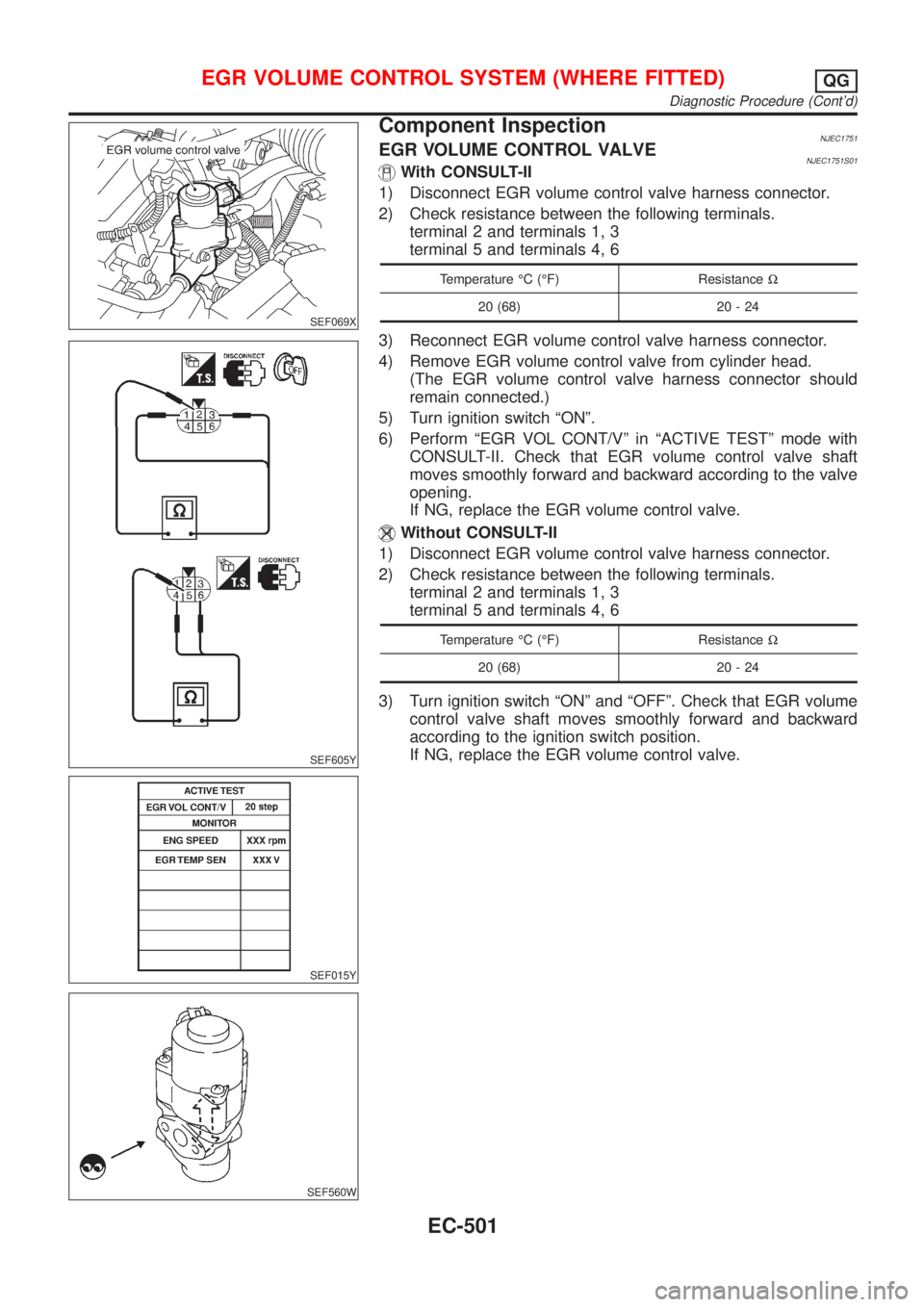
SEF069X
SEF605Y
SEF015Y
SEF560W
Component InspectionNJEC1751EGR VOLUME CONTROL VALVENJEC1751S01With CONSULT-II
1) Disconnect EGR volume control valve harness connector.
2) Check resistance between the following terminals.
terminal 2 and terminals 1, 3
terminal 5 and terminals 4, 6
Temperature ÉC (ÉF) ResistanceW
20 (68) 20 - 24
3) Reconnect EGR volume control valve harness connector.
4) Remove EGR volume control valve from cylinder head.
(The EGR volume control valve harness connector should
remain connected.)
5) Turn ignition switch ªONº.
6) Perform ªEGR VOL CONT/Vº in ªACTIVE TESTº mode with
CONSULT-II. Check that EGR volume control valve shaft
moves smoothly forward and backward according to the valve
opening.
If NG, replace the EGR volume control valve.
Without CONSULT-II
1) Disconnect EGR volume control valve harness connector.
2) Check resistance between the following terminals.
terminal 2 and terminals 1, 3
terminal 5 and terminals 4, 6
Temperature ÉC (ÉF) ResistanceW
20 (68) 20 - 24
3) Turn ignition switch ªONº and ªOFFº. Check that EGR volume
control valve shaft moves smoothly forward and backward
according to the ignition switch position.
If NG, replace the EGR volume control valve.
EGR VOLUME CONTROL SYSTEM (WHERE FITTED)QG
Diagnostic Procedure (Cont'd)
EC-501
Page 1339 of 2898
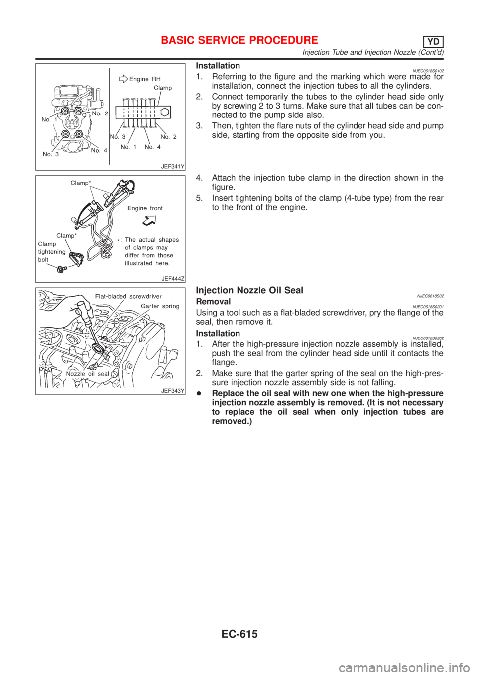
JEF341Y
InstallationNJEC0618S01021. Referring to the figure and the marking which were made for
installation, connect the injection tubes to all the cylinders.
2. Connect temporarily the tubes to the cylinder head side only
by screwing 2 to 3 turns. Make sure that all tubes can be con-
nected to the pump side also.
3. Then, tighten the flare nuts of the cylinder head side and pump
side, starting from the opposite side from you.
JEF444Z
4. Attach the injection tube clamp in the direction shown in the
figure.
5. Insert tightening bolts of the clamp (4-tube type) from the rear
to the front of the engine.
JEF343Y
Injection Nozzle Oil SealNJEC0618S02RemovalNJEC0618S0201Using a tool such as a flat-bladed screwdriver, pry the flange of the
seal, then remove it.
Installation
NJEC0618S02021. After the high-pressure injection nozzle assembly is installed,
push the seal from the cylinder head side until it contacts the
flange.
2. Make sure that the garter spring of the seal on the high-pres-
sure injection nozzle assembly side is not falling.
+Replace the oil seal with new one when the high-pressure
injection nozzle assembly is removed. (It is not necessary
to replace the oil seal when only injection tubes are
removed.)
BASIC SERVICE PROCEDUREYD
Injection Tube and Injection Nozzle (Cont'd)
EC-615
Page 1340 of 2898
JEF344Y
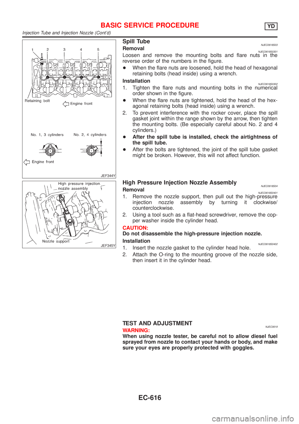
Spill TubeNJEC0618S03RemovalNJEC0618S0301Loosen and remove the mounting bolts and flare nuts in the
reverse order of the numbers in the figure.
+When the flare nuts are loosened, hold the head of hexagonal
retaining bolts (head inside) using a wrench.
Installation
NJEC0618S03021. Tighten the flare nuts and mounting bolts in the numerical
order shown in the figure.
+When the flare nuts are tightened, hold the head of the hex-
agonal retaining bolts (head inside) using a wrench.
2. To prevent interference with the rocker cover, place the spill
gasket joint within the range shown by the arrow, then tighten
the mounting bolts. (Be especially careful about No. 2 and 4
cylinders.)
+After the spill tube is installed, check the airtightness of
the spill tube.
+After the bolts are tightened, the joint of the spill tube gasket
might be broken. However, this will not affect function.
JEF345Y
High Pressure Injection Nozzle AssemblyNJEC0618S04RemovalNJEC0618S04011. Remove the nozzle support, then pull out the high-pressure
injection nozzle assembly by turning it clockwise/
counterclockwise.
2. Using a tool such as a flat-head screwdriver, remove the cop-
per washer inside the cylinder head.
CAUTION:
Do not disassemble the high-pressure injection nozzle.
Installation
NJEC0618S04021. Insert the nozzle gasket to the cylinder head hole.
2. Attach the O-ring to the mounting groove of the nozzle side,
then insert it in the cylinder head.
TEST AND ADJUSTMENTNJEC0619WARNING:
When using nozzle tester, be careful not to allow diesel fuel
sprayed from nozzle to contact your hands or body, and make
sure your eyes are properly protected with goggles.
BASIC SERVICE PROCEDUREYD
Injection Tube and Injection Nozzle (Cont'd)
EC-616
Page 1480 of 2898
9 CHECK INTERMITTENT INCIDENT
1. Perform ªTROUBLE DIAGNOSIS FOR INTERMITTENT INCIDENTº, EC-665.
©INSPECTION END
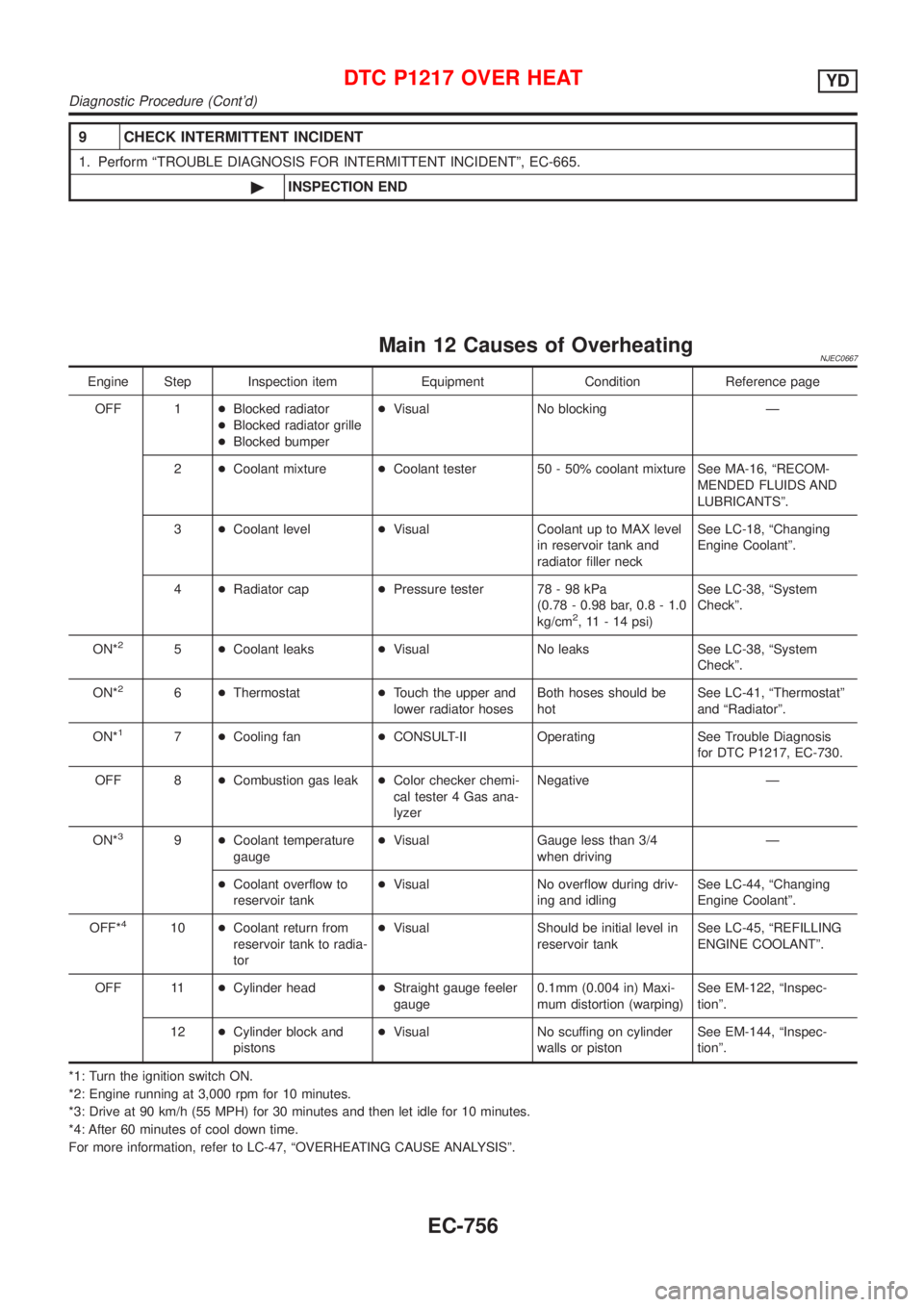
Main 12 Causes of OverheatingNJEC0667
Engine Step Inspection item Equipment Condition Reference page
OFF 1+Blocked radiator
+Blocked radiator grille
+Blocked bumper+Visual No blocking Ð
2+Coolant mixture+Coolant tester 50 - 50% coolant mixture See MA-16, ªRECOM-
MENDED FLUIDS AND
LUBRICANTSº.
3+Coolant level+Visual Coolant up to MAX level
in reservoir tank and
radiator filler neckSee LC-18, ªChanging
Engine Coolantº.
4+Radiator cap+Pressure tester 78 - 98 kPa
(0.78 - 0.98 bar, 0.8 - 1.0
kg/cm
2, 11 - 14 psi)See LC-38, ªSystem
Checkº.
ON*
25+Coolant leaks+Visual No leaks See LC-38, ªSystem
Checkº.
ON*
26+Thermostat+Touch the upper and
lower radiator hosesBoth hoses should be
hotSee LC-41, ªThermostatº
and ªRadiatorº.
ON*
17+Cooling fan+CONSULT-II Operating See Trouble Diagnosis
for DTC P1217, EC-730.
OFF 8+Combustion gas leak+Color checker chemi-
cal tester 4 Gas ana-
lyzerNegative Ð
ON*
39+Coolant temperature
gauge+Visual Gauge less than 3/4
when drivingÐ
+Coolant overflow to
reservoir tank+Visual No overflow during driv-
ing and idlingSee LC-44, ªChanging
Engine Coolantº.
OFF*
410+Coolant return from
reservoir tank to radia-
tor+Visual Should be initial level in
reservoir tankSee LC-45, ªREFILLING
ENGINE COOLANTº.
OFF 11+Cylinder head+Straight gauge feeler
gauge0.1mm (0.004 in) Maxi-
mum distortion (warping)See EM-122, ªInspec-
tionº.
12+Cylinder block and
pistons+Visual No scuffing on cylinder
walls or pistonSee EM-144, ªInspec-
tionº.
*1: Turn the ignition switch ON.
*2: Engine running at 3,000 rpm for 10 minutes.
*3: Drive at 90 km/h (55 MPH) for 30 minutes and then let idle for 10 minutes.
*4: After 60 minutes of cool down time.
For more information, refer to LC-47, ªOVERHEATING CAUSE ANALYSISº.
DTC P1217 OVER HEATYD
Diagnostic Procedure (Cont'd)
EC-756
Page 2135 of 2898
ENGINE MECHANICAL
SECTION
EM
CONTENTS
QG
PRECAUTIONS...............................................................4
Parts Requiring Angular Tightening .............................4
Liquid Gasket Application Procedure ..........................4
PREPARATION...............................................................5
Special Service Tools ..................................................5
Commercial Service Tools ...........................................7
NOISE, VIBRATION AND HARSHNESS (NVH)
TROUBLESHOOTING.....................................................9
NVH Troubleshooting - Engine Noise .........................9
OUTER COMPONENT PARTS..................................... 11
Removal and Installation ........................................... 11
MEASUREMENT OF COMPRESSION PRESSURE....15
DRIVE BELTS................................................................16
Checking ....................................................................16
AIR CLEANER...............................................................18
Cleaning and Changing .............................................18
VISCOUS PAPER TYPE...........................................18
DRY PAPER TYPE..................................................18
SPARK PLUG................................................................19
Checking and Changing ............................................19
OIL PAN.........................................................................20
Components...............................................................20
Removal .....................................................................20
Installation ..................................................................21
TIMING CHAIN..............................................................23
Components...............................................................23
Removal .....................................................................24
Inspection...................................................................27
Installation ..................................................................28
OIL SEAL.......................................................................32
Replacement ..............................................................32
VALVE OIL SEAL.....................................................32
FRONT OIL SEAL....................................................32
REAR OIL SEAL......................................................33
CYLINDER HEAD..........................................................34
Components...............................................................34
Removal .....................................................................35
Disassembly...............................................................37Inspection...................................................................37
CYLINDER HEAD DISTORTION...............................37
CAMSHAFT VISUAL CHECK....................................37
CAMSHAFT RUNOUT..............................................38
CAMSHAFT CAM HEIGHT.......................................38
CAMSHAFT JOURNAL CLEARANCE........................38
CAMSHAFT END PLAY............................................39
CAMSHAFT SPROCKET RUNOUT...........................39
VALVE GUIDE CLEARANCE....................................39
VALVE GUIDE REPLACEMENT................................40
VALVE SEATS.........................................................41
REPLACING VALVE SEAT FOR SERVICE PARTS....41
VALVE DIMENSIONS...............................................42
VALVE SPRING.......................................................42
VALVE LIFTER AND VALVE SHIM............................43
Valve Clearance.........................................................44
CHECKING.............................................................44
ADJUSTING............................................................45
Assembly ...................................................................46
Installation ..................................................................47
ENGINE ASSEMBLY.....................................................51
Removal and Installation ...........................................51
REMOVAL...............................................................52
INSTALLATION........................................................53
CYLINDER BLOCK.......................................................54
Components...............................................................54
Removal and Installation ...........................................55
Disassembly...............................................................55
PISTON AND CRANKSHAFT....................................55
Inspection...................................................................56
PISTON AND PISTON PIN CLEARANCE..................56
PISTON RING SIDE CLEARANCE............................56
PISTON RING END GAP..........................................56
CONNECTING ROD BEND AND TORSION...............57
CYLINDER BLOCK DISTORTION AND WEAR...........57
PISTON-TO-BORE CLEARANCE..............................58
CRANKSHAFT.........................................................59
BEARING CLEARANCE...........................................59
CONNECTING ROD BUSHING CLEARANCE
(SMALL END)
..........................................................61
Page 2136 of 2898
REPLACEMENT OF CONNECTING ROD
BUSHING (SMALL END)
..........................................62
FLYWHEEL/DRIVE PLATE RUNOUT........................62
Assembly ...................................................................62
PISTON..................................................................62
CRANKSHAFT.........................................................63
SERVICE DATA AND SPECIFICATIONS (SDS).........66
General Specifications ...............................................66
Compression Pressure ..............................................66
Belt Deflection............................................................67
Spark Plug .................................................................67
Cylinder Head ............................................................67
Valve ..........................................................................68
VALVE....................................................................68
VALVE SPRING.......................................................68
VALVE LIFTER........................................................68
VALVE CLEARANCE................................................69
VALVE GUIDE.........................................................69
AVAILABLE SHIMS..................................................69
VALVE SEAT...........................................................71
VALVE SEAT RESURFACE LIMIT.............................72
Camshaft and Camshaft Bearing ..............................72
Cylinder Block ............................................................73
Piston, Piston Ring and Piston Pin ...........................74
PISTON..................................................................74
PISTON RING.........................................................74
PISTON PIN............................................................74
Connecting Rod .........................................................75
Crankshaft..................................................................75
Main Bearing..............................................................75
STANDARD.............................................................75
UNDERSIZE............................................................75
Connecting Rod Bearing ...........................................76
STANDARD SIZE....................................................76
UNDERSIZE............................................................76
Bearing Clearance .....................................................76
Miscellaneous Components.......................................76
YD
PRECAUTIONS.............................................................77
Parts Requiring Angular Tightening ...........................77
Liquid Gasket Application Procedure ........................77
PREPARATION.............................................................78
Special Service Tools ................................................78
Commercial Service Tools .........................................80
NOISE, VIBRATION AND HARSHNESS (NVH)
TROUBLESHOOTING...................................................82
NVH Troubleshooting - Engine Noise .......................82
MEASUREMENT OF COMPRESSION PRESSURE....83
DRIVE BELTS................................................................85
Inspection...................................................................85
Adjustment .................................................................85
AIR CONDITIONER COMPRESSOR BELT................86
ALTERNATOR & WATER PUMP BELT.....................86
Removal .....................................................................86
Installation ..................................................................87
AIR CLEANER...............................................................88
Changing Air Cleaner Filter .......................................88
VISCOUS PAPER TYPE...........................................88
OIL PAN.........................................................................89
Components...............................................................89
Removal .....................................................................89
Installation ..................................................................91
TIMING CHAIN..............................................................94
Secondary Timing Chain ...........................................94
REMOVAL...............................................................94
INSPECTION...........................................................96
INSTALLATION........................................................96
Primary Timing Chain ................................................99
REMOVAL.............................................................100
INSPECTION.........................................................102
INSTALLATION......................................................102
INTAKE MANIFOLD....................................................107
Removal and Installation .........................................107
PREPARATIVE WORK...........................................107
FUEL PIPING........................................................108
INTAKE MANIFOLD...............................................108
EGR VOLUME CONTROL VALVE...........................108
WATER HOSE.......................................................108
Inspection.................................................................109
INTAKE MANIFOLD...............................................109
CATALYST.................................................................. 110
Removal and Installation ......................................... 110
PREPARATIVE WORK........................................... 110
CATALYST............................................................ 110
GUSSET............................................................... 111
EXHAUST MANIFOLD, TURBOCHARGER............... 112
Removal and Installation ......................................... 112
PREPARATIVE WORK........................................... 112
EXHAUST MANIFOLD AND TURBOCHARGER....... 112
EXHAUST MANIFOLD GASKET............................. 113
Disassembly and Assembly ..................................... 113
TURBOCHARGER................................................. 113
Inspection................................................................. 114
EXHAUST MANIFOLD........................................... 114
TURBOCHARGER................................................. 114
ROCKER COVER........................................................ 117
Removal and Installation ......................................... 117
PREPARATIVE WORK........................................... 117
ROCKER COVER.................................................. 117
CYLINDER HEAD........................................................ 119
Components............................................................. 119
Removal ...................................................................120
PREPARATIVE WORK...........................................120
CAMSHAFT...........................................................120
CYLINDER HEAD..................................................121
Disassembly.............................................................121
Inspection.................................................................122
CONTENTS(Cont'd)
EM-2