Page 2172 of 2898
SEM154D
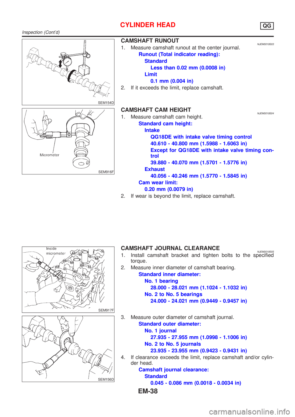
CAMSHAFT RUNOUTNJEM0019S031. Measure camshaft runout at the center journal.
Runout (Total indicator reading):
Standard
Less than 0.02 mm (0.0008 in)
Limit
0.1 mm (0.004 in)
2. If it exceeds the limit, replace camshaft.
SEM916F
CAMSHAFT CAM HEIGHTNJEM0019S041. Measure camshaft cam height.
Standard cam height:
Intake
QG18DE with intake valve timing control
40.610 - 40.800 mm (1.5988 - 1.6063 in)
Except for QG18DE with intake valve timing con-
trol
39.880 - 40.070 mm (1.5701 - 1.5776 in)
Exhaust
40.056 - 40.246 mm (1.5770 - 1.5845 in)
Cam wear limit:
0.20 mm (0.0079 in)
2. If wear is beyond the limit, replace camshaft.
SEM917F
CAMSHAFT JOURNAL CLEARANCENJEM0019S051. Install camshaft bracket and tighten bolts to the specified
torque.
2. Measure inner diameter of camshaft bearing.
Standard inner diameter:
No. 1 bearing
28.000 - 28.021 mm (1.1024 - 1.1032 in)
No. 2 to No. 5 bearings
24.000 - 24.021 mm (0.9449 - 0.9457 in)
SEM156D
3. Measure outer diameter of camshaft journal.
Standard outer diameter:
No. 1 journal
27.935 - 27.955 mm (1.0998 - 1.1006 in)
No. 2 to No. 5 journals
23.935 - 23.955 mm (0.9423 - 0.9431 in)
4. If clearance exceeds the limit, replace camshaft and/or cylin-
der head.
Camshaft journal clearance:
Standard
0.045 - 0.086 mm (0.0018 - 0.0034 in)
CYLINDER HEADQG
Inspection (Cont'd)
EM-38
Page 2173 of 2898
Limit
0.15 mm (0.0059 in)
SEM918F
CAMSHAFT END PLAYNJEM0019S061. Install camshaft in cylinder head. Refer to EM-47.
2. Measure camshaft end play.
Camshaft end play:
Standard
0.115 - 0.188 mm (0.0045 - 0.0074 in)
Limit
0.20 mm (0.0079 in)
3. If limit is exceeded, replace camshaft and remeasure end play.
+If limit is still exceeded after replacing camshaft, replace
cylinder head.
SEM919F
CAMSHAFT SPROCKET RUNOUTNJEM0019S071. Install sprocket on camshaft.
2. Measure camshaft sprocket runout.
Runout (Total indicator reading):
Limit 0.15 mm (0.0059 in)
3. If it exceeds the limit, replace camshaft sprocket.
SEM345D
VALVE GUIDE CLEARANCENJEM0019S081. Measure valve deflection as shown in figure. (Valve and valve
guide wear the most in this direction.)
Valve deflection limit (Dial gauge reading):
Intake & Exhaust
0.2 mm (0.008 in)
CYLINDER HEADQG
Inspection (Cont'd)
EM-39
Page 2174 of 2898
SEM938C
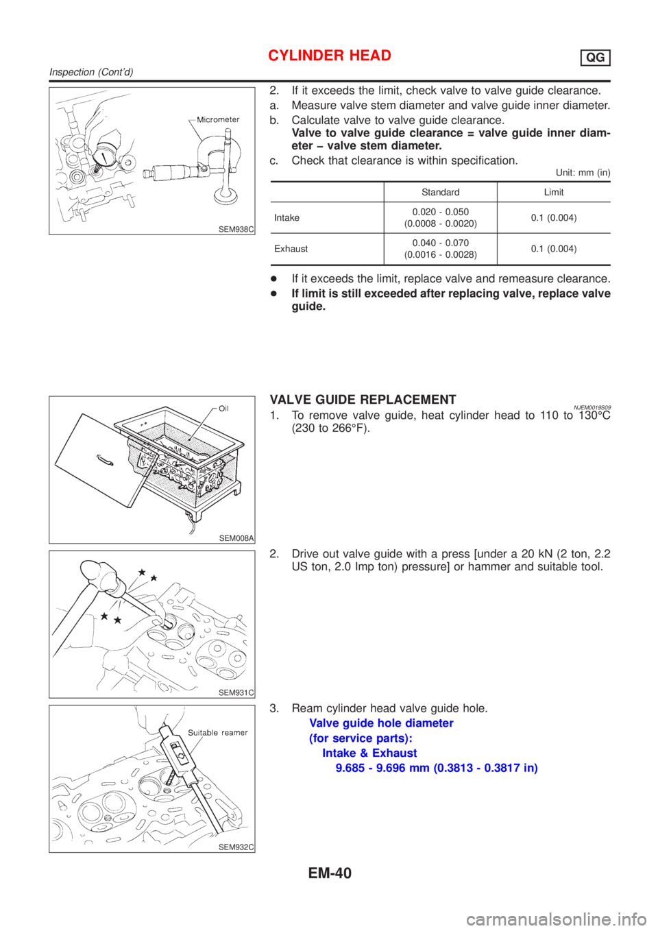
2. If it exceeds the limit, check valve to valve guide clearance.
a. Measure valve stem diameter and valve guide inner diameter.
b. Calculate valve to valve guide clearance.
Valve to valve guide clearance = valve guide inner diam-
eter þ valve stem diameter.
c. Check that clearance is within specification.
Unit: mm (in)
Standard Limit
Intake0.020 - 0.050
(0.0008 - 0.0020)0.1 (0.004)
Exhaust0.040 - 0.070
(0.0016 - 0.0028)0.1 (0.004)
+If it exceeds the limit, replace valve and remeasure clearance.
+If limit is still exceeded after replacing valve, replace valve
guide.
SEM008A
VALVE GUIDE REPLACEMENTNJEM0019S091. To remove valve guide, heat cylinder head to 110 to 130ÉC
(230 to 266ÉF).
SEM931C
2. Drive out valve guide with a press [under a 20 kN (2 ton, 2.2
US ton, 2.0 Imp ton) pressure] or hammer and suitable tool.
SEM932C
3. Ream cylinder head valve guide hole.
Valve guide hole diameter
(for service parts):
Intake & Exhaust
9.685 - 9.696 mm (0.3813 - 0.3817 in)
CYLINDER HEADQG
Inspection (Cont'd)
EM-40
Page 2175 of 2898
MEM096A
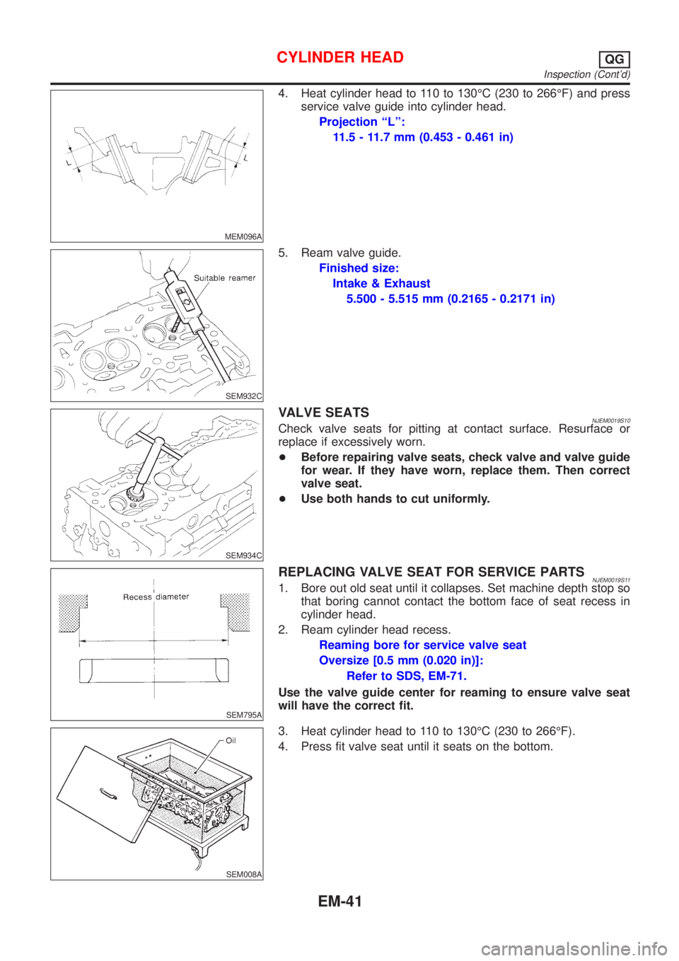
4. Heat cylinder head to 110 to 130ÉC (230 to 266ÉF) and press
service valve guide into cylinder head.
Projection ªLº:
11.5 - 11.7 mm (0.453 - 0.461 in)
SEM932C
5. Ream valve guide.
Finished size:
Intake & Exhaust
5.500 - 5.515 mm (0.2165 - 0.2171 in)
SEM934C
VALVE SEATSNJEM0019S10Check valve seats for pitting at contact surface. Resurface or
replace if excessively worn.
+Before repairing valve seats, check valve and valve guide
for wear. If they have worn, replace them. Then correct
valve seat.
+Use both hands to cut uniformly.
SEM795A
REPLACING VALVE SEAT FOR SERVICE PARTSNJEM0019S111. Bore out old seat until it collapses. Set machine depth stop so
that boring cannot contact the bottom face of seat recess in
cylinder head.
2. Ream cylinder head recess.
Reaming bore for service valve seat
Oversize [0.5 mm (0.020 in)]:
Refer to SDS, EM-71.
Use the valve guide center for reaming to ensure valve seat
will have the correct fit.
SEM008A
3. Heat cylinder head to 110 to 130ÉC (230 to 266ÉF).
4. Press fit valve seat until it seats on the bottom.
CYLINDER HEADQG
Inspection (Cont'd)
EM-41
Page 2176 of 2898
SEM892B
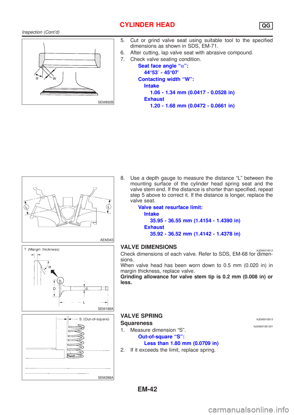
5. Cut or grind valve seat using suitable tool to the specified
dimensions as shown in SDS, EM-71.
6. After cutting, lap valve seat with abrasive compound.
7. Check valve seating condition.
Seat face angle ªaº:
44É53¢- 45É07¢
Contacting width ªWº:
Intake
1.06 - 1.34 mm (0.0417 - 0.0528 in)
Exhaust
1.20 - 1.68 mm (0.0472 - 0.0661 in)
AEM343
8. Use a depth gauge to measure the distance ªLº between the
mounting surface of the cylinder head spring seat and the
valve stem end. If the distance is shorter than specified, repeat
step 5 above to correct it. If the distance is longer, replace the
valve seat.
Valve seat resurface limit:
Intake
35.95 - 36.55 mm (1.4154 - 1.4390 in)
Exhaust
35.92 - 36.52 mm (1.4142 - 1.4378 in)
SEM188A
VALVE DIMENSIONSNJEM0019S12Check dimensions of each valve. Refer to SDS, EM-68 for dimen-
sions.
When valve head has been worn down to 0.5 mm (0.020 in) in
margin thickness, replace valve.
Grinding allowance for valve stem tip is 0.2 mm (0.008 in) or
less.
SEM288A
VALVE SPRINGNJEM0019S13SquarenessNJEM0019S13011. Measure dimension ªSº.
Out-of-square ªSº:
Less than 1.80 mm (0.0709 in)
2. If it exceeds the limit, replace spring.
CYLINDER HEADQG
Inspection (Cont'd)
EM-42
Page 2177 of 2898
EM113
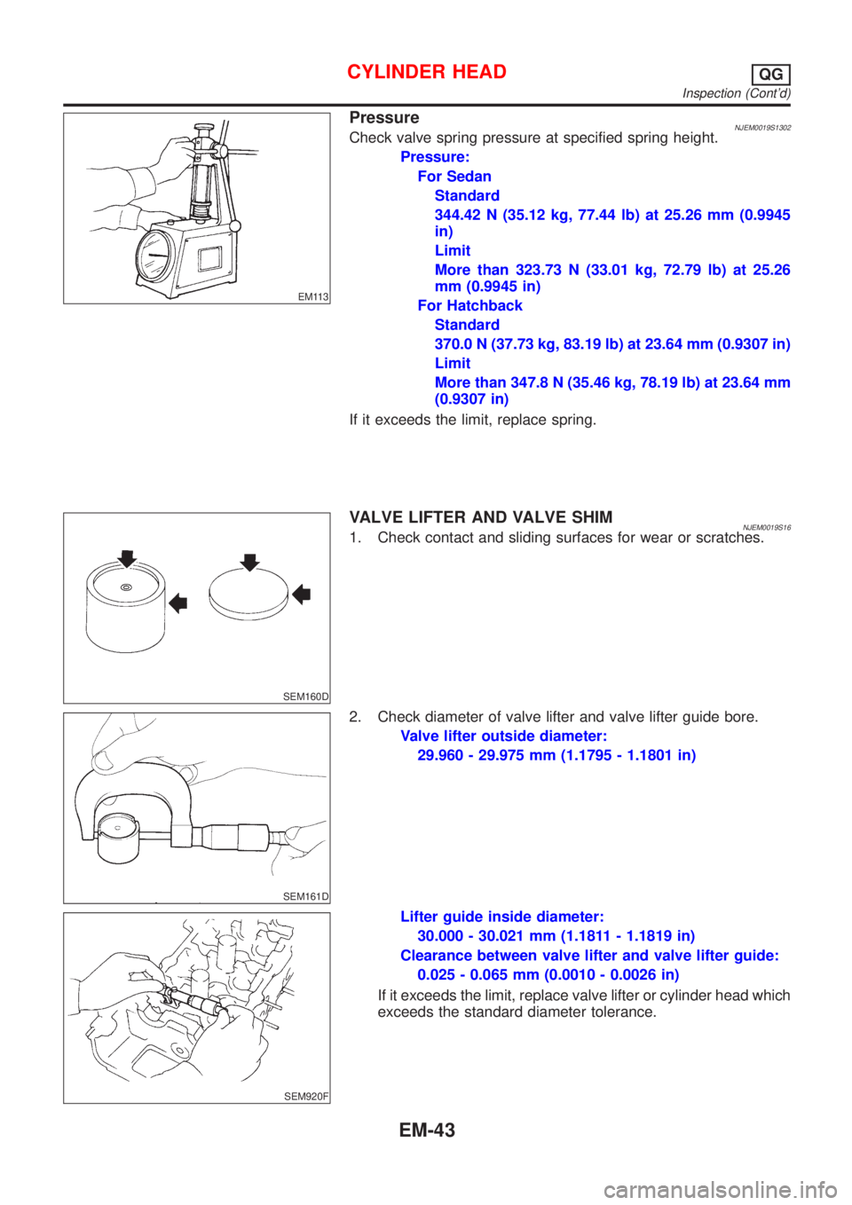
PressureNJEM0019S1302Check valve spring pressure at specified spring height.
Pressure:
For Sedan
Standard
344.42 N (35.12 kg, 77.44 lb) at 25.26 mm (0.9945
in)
Limit
More than 323.73 N (33.01 kg, 72.79 lb) at 25.26
mm (0.9945 in)
For Hatchback
Standard
370.0 N (37.73 kg, 83.19 lb) at 23.64 mm (0.9307 in)
Limit
More than 347.8 N (35.46 kg, 78.19 lb) at 23.64 mm
(0.9307 in)
If it exceeds the limit, replace spring.
SEM160D
VALVE LIFTER AND VALVE SHIMNJEM0019S161. Check contact and sliding surfaces for wear or scratches.
SEM161D
2. Check diameter of valve lifter and valve lifter guide bore.
Valve lifter outside diameter:
29.960 - 29.975 mm (1.1795 - 1.1801 in)
SEM920F
Lifter guide inside diameter:
30.000 - 30.021 mm (1.1811 - 1.1819 in)
Clearance between valve lifter and valve lifter guide:
0.025 - 0.065 mm (0.0010 - 0.0026 in)
If it exceeds the limit, replace valve lifter or cylinder head which
exceeds the standard diameter tolerance.
CYLINDER HEADQG
Inspection (Cont'd)
EM-43
Page 2178 of 2898
SEM921F
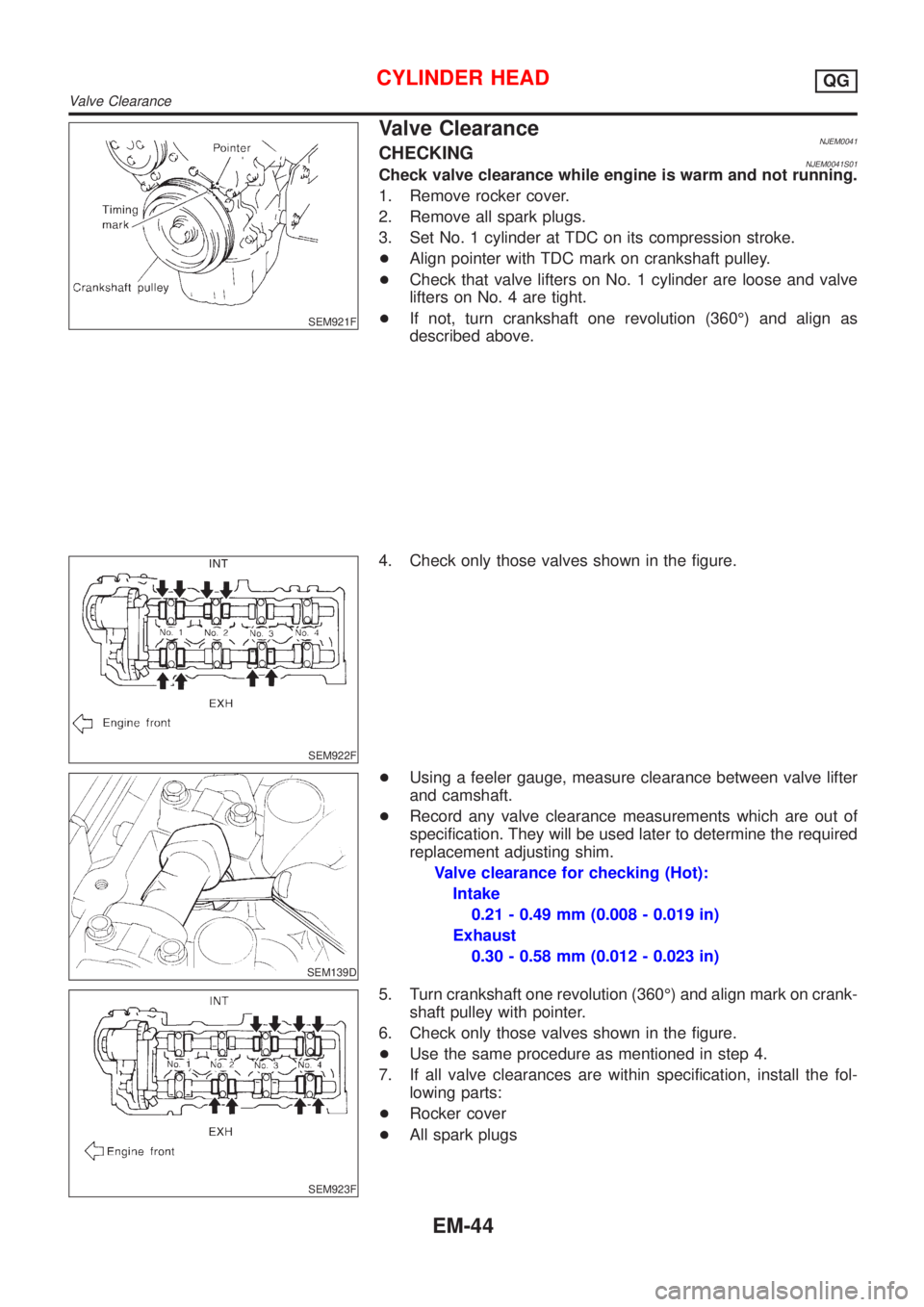
Valve ClearanceNJEM0041CHECKINGNJEM0041S01Check valve clearance while engine is warm and not running.
1. Remove rocker cover.
2. Remove all spark plugs.
3. Set No. 1 cylinder at TDC on its compression stroke.
+Align pointer with TDC mark on crankshaft pulley.
+Check that valve lifters on No. 1 cylinder are loose and valve
lifters on No. 4 are tight.
+If not, turn crankshaft one revolution (360É) and align as
described above.
SEM922F
4. Check only those valves shown in the figure.
SEM139D
+Using a feeler gauge, measure clearance between valve lifter
and camshaft.
+Record any valve clearance measurements which are out of
specification. They will be used later to determine the required
replacement adjusting shim.
Valve clearance for checking (Hot):
Intake
0.21 - 0.49 mm (0.008 - 0.019 in)
Exhaust
0.30 - 0.58 mm (0.012 - 0.023 in)
SEM923F
5. Turn crankshaft one revolution (360É) and align mark on crank-
shaft pulley with pointer.
6. Check only those valves shown in the figure.
+Use the same procedure as mentioned in step 4.
7. If all valve clearances are within specification, install the fol-
lowing parts:
+Rocker cover
+All spark plugs
CYLINDER HEADQG
Valve Clearance
EM-44
Page 2179 of 2898
SEM941F
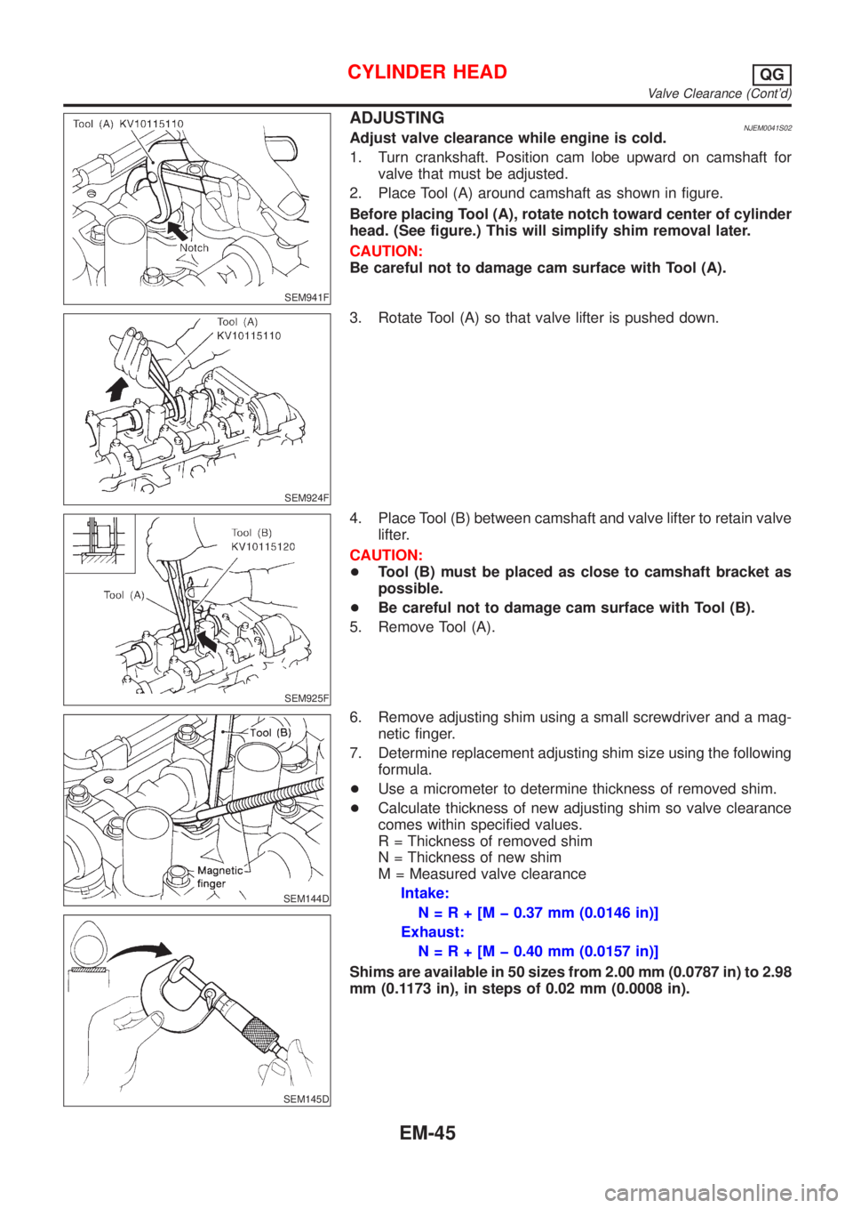
ADJUSTINGNJEM0041S02Adjust valve clearance while engine is cold.
1. Turn crankshaft. Position cam lobe upward on camshaft for
valve that must be adjusted.
2. Place Tool (A) around camshaft as shown in figure.
Before placing Tool (A), rotate notch toward center of cylinder
head. (See figure.) This will simplify shim removal later.
CAUTION:
Be careful not to damage cam surface with Tool (A).
SEM924F
3. Rotate Tool (A) so that valve lifter is pushed down.
SEM925F
4. Place Tool (B) between camshaft and valve lifter to retain valve
lifter.
CAUTION:
+Tool (B) must be placed as close to camshaft bracket as
possible.
+Be careful not to damage cam surface with Tool (B).
5. Remove Tool (A).
SEM144D
SEM145D
6. Remove adjusting shim using a small screwdriver and a mag-
netic finger.
7. Determine replacement adjusting shim size using the following
formula.
+Use a micrometer to determine thickness of removed shim.
+Calculate thickness of new adjusting shim so valve clearance
comes within specified values.
R = Thickness of removed shim
N = Thickness of new shim
M = Measured valve clearance
Intake:
N=R+[Mþ0.37 mm (0.0146 in)]
Exhaust:
N=R+[Mþ0.40 mm (0.0157 in)]
Shims are available in 50 sizes from 2.00 mm (0.0787 in) to 2.98
mm (0.1173 in), in steps of 0.02 mm (0.0008 in).
CYLINDER HEADQG
Valve Clearance (Cont'd)
EM-45