2001 NISSAN ALMERA fuel filter location
[x] Cancel search: fuel filter locationPage 731 of 2898

ECM Terminals and Reference Value .....................578
Wiring Diagram ........................................................579
Diagnostic Procedure - Load Signal - .....................583
Diagnostic Procedure - Heater Control Panel
(Fan Switch) - ..........................................................589
Component Inspection .............................................590
MI & DATA LINK CONNECTORS..............................591
Wiring Diagram ........................................................591
SERVICE DATA AND SPECIFICATIONS (SDS).......593
Fuel Pressure Regulator..........................................593
Idle Speed and Ignition Timing ................................593
Mass Air Flow Sensor..............................................593
Intake Air Temperature Sensor ................................593
Engine Coolant Temperature Sensor ......................593
Throttle Position Sensor ..........................................593
Heated Oxygen Sensor 1 Heater (Front) ................593
Heated Oxygen Sensor 2 Heater (Rear).................593
Fuel Tank Temperature Sensor (Where Fitted) .......594
EGR Volume Control Valve (Where Fitted) .............594
EGR Temperature Sensor (Where Fitted) ...............594
EVAP Canister Purge Volume Control Valve ..........594
IACV-AAC Valve ......................................................594
Injector .....................................................................594
Ignition Coil with Power Transistor ..........................594
Condenser ...............................................................594
Fuel Pump ...............................................................594
Crankshaft Position Sensor (POS) ..........................595
Camshaft Position Sensor (PHASE) .......................595
YD
TROUBLE DIAGNOSIS - INDEX................................596
Alphabetical & P No. Index for DTC .......................596
PRECAUTIONS...........................................................598
Supplemental Restraint System (SRS)²AIR
BAG²and²SEAT BELT PRE-TENSIONER²...........598
Engine Fuel & Emission Control System ................599
Precautions ..............................................................600
Wiring Diagrams and Trouble Diagnosis .................601
PREPARATION...........................................................602
Special Service Tools ..............................................602
ENGINE AND EMISSION CONTROL OVERALL
SYSTEM.......................................................................603
Engine Control Component Parts Location .............603
Circuit Diagram ........................................................606
System Diagram ......................................................608
System Chart ...........................................................609
ENGINE AND EMISSION BASIC CONTROL
SYSTEM DESCRIPTION.............................................610
Fuel Injection Control System .................................610
Fuel Injection Timing Control System...................... 611
Air Conditioning Cut Control ....................................612Fuel Cut Control (at no load & high engine
speed) ......................................................................612
Crankcase Ventilation System .................................613
BASIC SERVICE PROCEDURE.................................614
Injection Tube and Injection Nozzle ........................614
Electronic Control Fuel Injection Pump ...................618
Fuel Filter .................................................................625
ON BOARD DIAGNOSTIC SYSTEM
DESCRIPTION.............................................................627
DTC and MI Detection Logic ...................................627
Diagnostic Trouble Code (DTC) ..............................627
Malfunction Indicator (MI) ........................................628
CONSULT-II .............................................................632
TROUBLE DIAGNOSIS - INTRODUCTION................637
Introduction ..............................................................637
Work Flow ................................................................639
TROUBLE DIAGNOSIS - BASIC INSPECTION.........641
Basic Inspection.......................................................641
TROUBLE DIAGNOSIS - GENERAL
DESCRIPTION.............................................................646
Symptom Matrix Chart .............................................646
CONSULT-II Reference Value in Data Monitor
Mode ........................................................................656
Major Sensor Reference Graph in Data Monitor
Mode ........................................................................658
ECM Terminals and Reference Value .....................659
TROUBLE DIAGNOSIS FOR INTERMITTENT
INCIDENT.....................................................................665
Description ...............................................................665
Diagnostic Procedure ..............................................665
TROUBLE DIAGNOSIS FOR POWER SUPPLY........666
Main Power Supply and Ground Circuit ..................666
DTC P0100 MASS AIR FLOW SEN...........................673
Component Description ...........................................673
CONSULT-II Reference Value in Data Monitor
Mode ........................................................................673
ECM Terminals and Reference Value .....................673
On Board Diagnosis Logic.......................................673
DTC Confirmation Procedure ..................................673
Wiring Diagram ........................................................675
Diagnostic Procedure ..............................................677
DTC P0115 COOLANT TEMP SEN............................680
Description ...............................................................680
On Board Diagnosis Logic.......................................680
DTC Confirmation Procedure ..................................680
Wiring Diagram ........................................................682
Diagnostic Procedure ..............................................683
DTC P0120 ACCEL POS SENSOR............................685
Description ...............................................................685
CONSULT-II Reference Value in Data Monitor
Mode ........................................................................685
ECM Terminals and Reference Value .....................685
CONTENTS(Cont'd)
EC-7
Page 764 of 2898

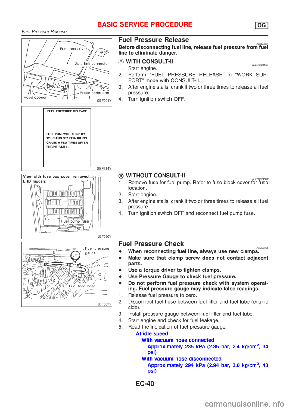
SEF094Y
SEF214Y
Fuel Pressure ReleaseNJEC0024Before disconnecting fuel line, release fuel pressure from fuel
line to eliminate danger.
WITH CONSULT-IINJEC0024S011. Start engine.
2. Perform ªFUEL PRESSURE RELEASEº in ªWORK SUP-
PORTº mode with CONSULT-II.
3. After engine stalls, crank it two or three times to release all fuel
pressure.
4. Turn ignition switch OFF.
JEF086Y
WITHOUT CONSULT-IINJEC0024S021. Remove fuse for fuel pump. Refer to fuse block cover for fuse
location.
2. Start engine.
3. After engine stalls, crank it two or three times to release all fuel
pressure.
4. Turn ignition switch OFF and reconnect fuel pump fuse.
JEF087Y
Fuel Pressure CheckNJEC0025+When reconnecting fuel line, always use new clamps.
+Make sure that clamp screw does not contact adjacent
parts.
+Use a torque driver to tighten clamps.
+Use Pressure Gauge to check fuel pressure.
+Do not perform fuel pressure check with system operat-
ing. Fuel pressure gauge may indicate false readings.
1. Release fuel pressure to zero.
2. Disconnect fuel hose between fuel filter and fuel tube (engine
side).
3. Install pressure gauge between fuel filter and fuel tube.
4. Start engine and check for fuel leakage.
5. Read the indication of fuel pressure gauge.
At idle speed:
With vacuum hose connected
Approximately 235 kPa (2.35 bar, 2.4 kg/cm
2,34
psi)
With vacuum hose disconnected
Approximately 294 kPa (2.94 bar, 3.0 kg/cm
2,43
psi)
BASIC SERVICE PROCEDUREQG
Fuel Pressure Release
EC-40