2001 NISSAN ALMERA navigation system
[x] Cancel search: navigation systemPage 1561 of 2898
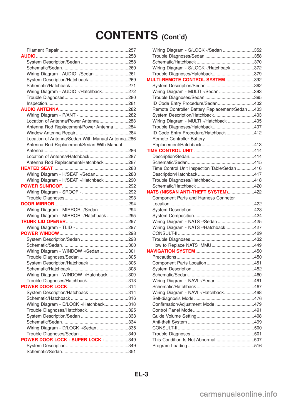
Filament Repair .......................................................257
AUDIO..........................................................................258
System Description/Sedan ......................................258
Schematic/Sedan .....................................................260
Wiring Diagram - AUDIO -/Sedan ...........................261
System Description/Hatchback ................................269
Schematic/Hatchback ..............................................271
Wiring Diagram - AUDIO -/Hatchback .....................272
Trouble Diagnoses...................................................280
Inspection.................................................................281
AUDIO ANTENNA.......................................................282
Wiring Diagram - P/ANT - .......................................282
Location of Antenna/Power Antenna .......................283
Antenna Rod Replacement/Power Antenna ............284
Window Antenna Repair ..........................................284
Location of Antenna/Sedan With Manual Antenna..286
Antenna Rod Replacement/Sedan With Manual
Antenna....................................................................286
Location of Antenna/Hatchback ...............................287
Antenna Rod Replacement/Hatchback ...................287
HEATED SEAT............................................................288
Wiring Diagram - H/SEAT -/Sedan ..........................288
Wiring Diagram - H/SEAT -/Hatchback ...................290
POWER SUNROOF.....................................................292
Wiring Diagram - SROOF - .....................................292
Trouble Diagnoses...................................................293
DOOR MIRROR...........................................................294
Wiring Diagram - MIRROR -/Sedan ........................294
Wiring Diagram - MIRROR -/Hatchback .................295
TRUNK LID OPENER..................................................297
Wiring Diagram - TLID - ..........................................297
POWER WINDOW.......................................................298
System Description/Sedan ......................................298
Schematic/Sedan .....................................................300
Wiring Diagram - WINDOW -/Sedan .......................301
Trouble Diagnoses/Sedan .......................................305
System Description/Hatchback ................................306
Schematic/Hatchback ..............................................308
Wiring Diagram - WINDOW -/Hatchback ................309
Trouble Diagnoses/Hatchback.................................313
POWER DOOR LOCK.................................................314
System Description/Hatchback ................................314
Schematic/Hatchback ..............................................316
Wiring Diagram - D/LOCK -/Hatchback...................318
Trouble Diagnoses/Hatchback.................................325
System Description/Sedan ......................................333
Schematic/Sedan .....................................................334
Wiring Diagram - D/LOCK -/Sedan .........................335
Trouble Diagnoses/Sedan .......................................340
POWER DOOR LOCK - SUPER LOCK -...................349
System Description ..................................................349
Schematic/Sedan .....................................................351Wiring Diagram - S/LOCK -/Sedan .........................352
Trouble Diagnoses/Sedan .......................................358
Schematic/Hatchback ..............................................370
Wiring Diagram - S/LOCK -/Hatchback ...................372
Trouble Diagnoses/Hatchback.................................379
MULTI-REMOTE CONTROL SYSTEM.......................392
System Description/Sedan ......................................392
Wiring Diagram - MULTI -/Sedan ............................393
Trouble Diagnoses/Sedan .......................................395
ID Code Entry Procedure/Sedan .............................402
Remote Controller Battery Replacement/Sedan .....403
System Description/Hatchback ................................403
Wiring Diagram - MULTI -/Hatchback .....................405
Trouble Diagnoses/Hatchback.................................407
ID Code Entry Procedure/Hatchback ......................412
Remote Controller Battery
Replacement/Hatchback ..........................................413
TIME CONTROL UNIT................................................414
Description/Sedan....................................................414
Schematic/Sedan .....................................................415
Time Control Unit Inspection Table/Sedan ..............416
Description/Hatchback .............................................417
Trouble Diagnoses/Hatchback.................................418
Schematic/Hatchback ..............................................420
NATS (NISSAN ANTI-THEFT SYSTEM).....................422
Component Parts and Harness Connetor
Location ...................................................................422
System Description ..................................................423
System Composition ................................................424
Wiring Diagram - NATS -/Sedan .............................425
Wiring Diagram - NATS -/Hatchback.......................427
CONSULT-II .............................................................429
Trouble Diagnoses...................................................432
How to Replace NATS IMMU ..................................449
NAVIGATION SYSTEM...............................................450
Precautions ..............................................................450
Component Parts Location ......................................451
System Description ..................................................452
Schematic/Sedan .....................................................460
Wiring Diagram - NAVI -/Sedan ..............................461
Schematic/Hatchback ..............................................467
Wiring Diagram - NAVI -/Hatchback ........................468
Self-diagnosis Mode ................................................476
Confirmation/Adjustment Mode ...............................479
Control Panel Mode .................................................491
Guide Volume Setting ..............................................498
Anti-theft System .....................................................499
CONSULT-II .............................................................500
Trouble Diagnoses...................................................501
This Condition Is Not Abnormal...............................507
Program Loading .....................................................516
CONTENTS(Cont'd)
EL-3
Page 1816 of 2898
System Description/Sedan=NJEL0381Refer to Owner's Manual for audio system operating instructions.
Power is supplied at all times
+through 15A fuse (No. 32, located in the fusible link and fuse block)
+to audio unit terminal 9
+to CD auto changer terminal 32.
With the ignition switch in the ACC or ON position, power is supplied
+through 10A fuse [No. 1, located in the fuse block (J/B)]
+to audio unit terminal 3,
+to CD auto changer terminal 36
Ground is supplied through the case of the audio unit.
Audio signals are supplied
+through audio unit terminals 7, 10, 11, 12, 13, 14, 15, 16
+to terminals 1 and 2 of front door speaker LH and RH,
+to terminals 1 and 2 of rear door speaker LH and RH and
+to terminals 1 and 2 of pillar tweeter LH and RH (with 6 speakers)
When the navigation system is triggered,
power is supplied
+through navi control unit terminal 46
+to speaker relay terminal 2
Ground is supplied
+through navi control unit terminal 44
+to speaker relay terminal 1
With power and ground supplied, the relay is energized, and then audio signal is interrupted to front door
speaker RH (LHD models) or LH (RHD models), and pillar tweeter RH (LHD models) or LH (RHD models)
For detailed, refer to ªNAVIGATION SYSTEMº.
NATS AUDIO LINKNJEL0381S04DescriptionNJEL0381S0401The link with the NATS IMMU implies that the audio unit can basically only be operated if connected to the
matching NATS IMMU to which the audio unit was initially fitted on the production line.
Since radio operation is impossible after the link with the NATS is disrupted theft of the audio unit is basically
useless since special equipment is required to reset the audio unit.
Initialization process for audio units that are linked to the NATS IMMU
New audio units will be delivered to the factories in the ªNEWº state, i.e. ready to be linked with the vehicle's
NATS. When the audio unit in ªNEWº state is first switched on at the factory, it will start up communication
with the vehicle's immobiliser control unit (IMMU) and send a code (the ªaudio unit Codeº) to the IMMU. The
IMMU will then store this code, which is unique to each audio unit, in its (permanent) memory.
Upon receipt of the code by the IMMU, the NATS will confirm correct receipt of the audio unit code to the audio
unit. Hereafter, the audio unit will operate as normal.
During the initialisation process, ªNEWº is displayed on the audio unit display. Normally though, communica-
tion between audio unit and IMMU takes such a short time (300 ms) that the audio unit seems to switch on
directly without showing ªNEWº on its display.
Normal operation
Each time the audio unit is switched on afterwards, the audio unit code will be verified between the audio unit
and the NATS before the audio unit becomes operational. During the code verification process, ªWAITº is
shown on the audio unit display. Again, the communication takes such a short time (300 ms) that the audio
unit seems to switch on directly without showing ªWAITº on its display.
When the radio is locked
In case of a audio unit being linked with the vehicle's NATS (immobilizer system), disconnection of the link
between the audio unit and the IMMU will cause the audio unit to switch into the lock (ªSECUREº) mode in
which the audio unit is fully inoperative. Hence, repair of the audio unit is basically impossible, unless the audio
unit is reset to the ªNEWº state for which special decoding equipment is required.
Clarion has provided their authorized service representatives with so called ªdecoder boxesº which can bring
the audio unit back to the ªNEWº state, enabling the audio unit to be switched on after which repair can be
AUDIO
System Description/Sedan
EL-258
Page 1827 of 2898
System Description/Hatchback=NJEL0497Refer to Owner's Manual for audio system operating instructions.
Power is supplied at all times
+through 15A fuse (No. 32, located in the fusible link and fuse block)
+to audio unit terminal 9
+to CD auto changer terminal 32.
With the ignition switch in the ACC or ON position, power is supplied
+through 10A fuse [No. 1, located in the fuse block (J/B)]
+to audio unit terminal 3,
+to CD auto changer terminal 36 and
Ground is supplied through the case of the audio unit.
Audio signals are supplied
+through audio unit terminals 7, 10, 11, 12, 13, 14, 15, 16
+to terminals 1 and 2 of front door speaker LH and RH,
+to terminals 1 and 2 of rear door speaker LH and RH and
+to terminals 1 and 2 of pillar tweeter LH and RH (with 6 speakers)
When the navigation system is triggered,
power is supplied
+through navi control unit terminal 46
+to speaker relay terminal 2
Ground is supplied
+through navi control unit terminal 44
+to speaker relay terminal 1
With power and ground supplied, the relay is energized, and then audio signal is interrupted to front door
speaker RH (LHD models) or LH (RHD models), and pillar tweeter RH (LHD models) or LH (RHD models)
For detailed, refer to ªNAVIGATION SYSTEMº.
NATS AUDIO LINKNJEL0497S01DescriptionNJEL0497S0101The link with the NATS IMMU implies that the audio unit can basically only be operated if connected to the
matching NATS IMMU to which the audio unit was initially fitted on the production line.
Since radio operation is impossible after the link with the NATS is disrupted theft of the audio unit is basically
useless since special equipment is required to reset the audio unit.
Initialization process for audio units that are linked to the NATS IMMU
New audio units will be delivered to the factories in the ªNEWº state, i.e. ready to be linked with the vehicle's
NATS. When the audio unit in ªNEWº state is first switched on at the factory, it will start up communication
with the vehicle's immobiliser control unit (IMMU) and send a code (the ªaudio unit Codeº) to the IMMU. The
IMMU will then store this code, which is unique to each audio unit, in its (permanent) memory.
Upon receipt of the code by the IMMU, the NATS will confirm correct receipt of the audio unit code to the audio
unit. Hereafter, the audio unit will operate as normal.
During the initialisation process, ªNEWº is displayed on the audio unit display. Normally though, communica-
tion between audio unit and IMMU takes such a short time (300 ms) that the audio unit seems to switch on
directly without showing ªNEWº on its display.
Normal operation
Each time the audio unit is switched on afterwards, the audio unit code will be verified between the audio unit
and the NATS before the audio unit becomes operational. During the code verification process, ªWAITº is
shown on the audio unit display. Again, the communication takes such a short time (300 ms) that the audio
unit seems to switch on directly without showing ªWAITº on its display.
When the radio is locked
In case of a audio unit being linked with the vehicle's NATS (immobilizer system), disconnection of the link
between the audio unit and the IMMU will cause the audio unit to switch into the lock (ªSECUREº) mode in
which the audio unit is fully inoperative. Hence, repair of the audio unit is basically impossible, unless the audio
unit is reset to the ªNEWº state for which special decoding equipment is required.
Clarion has provided their authorized service representatives with so called ªdecoder boxesº which can bring
the audio unit back to the ªNEWº state, enabling the audio unit to be switched on after which repair can be
AUDIO
System Description/Hatchback
EL-269
Page 1982 of 2898
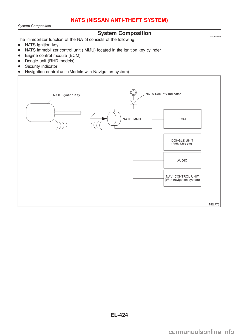
System Composition=NJEL0408The immobilizer function of the NATS consists of the following:
+NATS ignition key
+NATS immobilizer control unit (IMMU) located in the ignition key cylinder
+Engine control module (ECM)
+Dongle unit (RHD models)
+Security indicator
+Navigation control unit (Models with Navigation system)
NEL776
NATS (NISSAN ANTI-THEFT SYSTEM)
System Composition
EL-424
Page 2008 of 2898

PrecautionsNJEL0514WARNING:
Do not attempt to disassemble the monitor. Parts of the monitor have high voltages that can result in
severe and dangerous electric shock.
CAUTION:
+Do not reverse battery connections.
+Do not attach unauthorized parts.
+Protect the unit from severe impact.
NOTE:
Before beginning repair, determine whether or not the unit is defective. Refer to ªThis Condition Is Not
Abnormalº (EL-507).
NAVIGATION SYSTEM
Precautions
EL-450
Page 2009 of 2898

Component Parts LocationNJEL0515
SEL501X
NAVIGATION SYSTEM
Component Parts Location
EL-451
Page 2010 of 2898
SEL504X
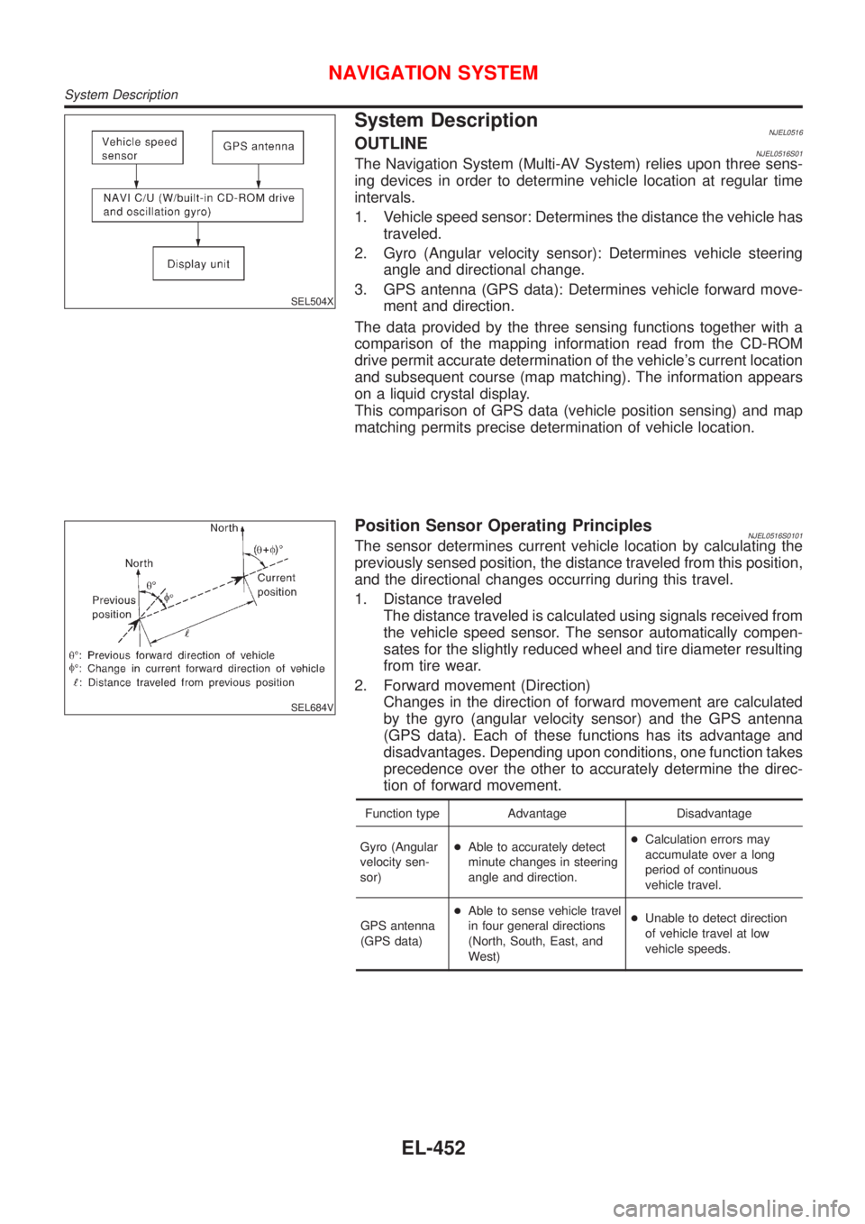
System DescriptionNJEL0516OUTLINENJEL0516S01The Navigation System (Multi-AV System) relies upon three sens-
ing devices in order to determine vehicle location at regular time
intervals.
1. Vehicle speed sensor: Determines the distance the vehicle has
traveled.
2. Gyro (Angular velocity sensor): Determines vehicle steering
angle and directional change.
3. GPS antenna (GPS data): Determines vehicle forward move-
ment and direction.
The data provided by the three sensing functions together with a
comparison of the mapping information read from the CD-ROM
drive permit accurate determination of the vehicle's current location
and subsequent course (map matching). The information appears
on a liquid crystal display.
This comparison of GPS data (vehicle position sensing) and map
matching permits precise determination of vehicle location.
SEL684V
Position Sensor Operating PrinciplesNJEL0516S0101The sensor determines current vehicle location by calculating the
previously sensed position, the distance traveled from this position,
and the directional changes occurring during this travel.
1. Distance traveled
The distance traveled is calculated using signals received from
the vehicle speed sensor. The sensor automatically compen-
sates for the slightly reduced wheel and tire diameter resulting
from tire wear.
2. Forward movement (Direction)
Changes in the direction of forward movement are calculated
by the gyro (angular velocity sensor) and the GPS antenna
(GPS data). Each of these functions has its advantage and
disadvantages. Depending upon conditions, one function takes
precedence over the other to accurately determine the direc-
tion of forward movement.
Function type Advantage Disadvantage
Gyro (Angular
velocity sen-
sor)+Able to accurately detect
minute changes in steering
angle and direction.+Calculation errors may
accumulate over a long
period of continuous
vehicle travel.
GPS antenna
(GPS data)+Able to sense vehicle travel
in four general directions
(North, South, East, and
West)+Unable to detect direction
of vehicle travel at low
vehicle speeds.
NAVIGATION SYSTEM
System Description
EL-452
Page 2011 of 2898
SEL685V
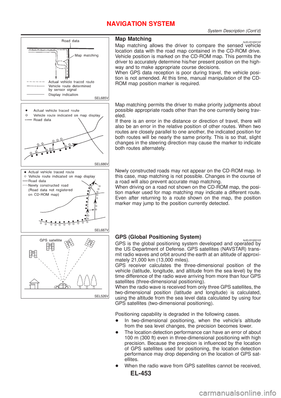
Map MatchingNJEL0516S0102Map matching allows the driver to compare the sensed vehicle
location data with the road map contained in the CD-ROM drive.
Vehicle position is marked on the CD-ROM map. This permits the
driver to accurately determine his/her present position on the high-
way and to make appropriate course decisions.
When GPS data reception is poor during travel, the vehicle posi-
tion is not amended. At this time, manual manipulation of the CD-
ROM map position marker is required.
SEL686V
Map matching permits the driver to make priority judgments about
possible appropriate roads other than the one currently being trav-
eled.
If there is an error in the distance or direction of travel, there will
also be an error in the relative position of other routes. When two
routes are closely parallel to one another, the indicated position for
both routes will be nearly the same priority. This is so that, slight
changes in the steering direction may cause the marker to indicate
both routes alternately.
SEL687V
Newly constructed roads may not appear on the CD-ROM map. In
this case, map matching is not possible. Changes in the course of
a road will also prevent accurate map matching.
When driving on a road not shown on the CD-ROM map, the posi-
tion marker used for map matching may indicate a different route.
Even after returning to a route shown on the map, the position
marker may jump to the position currently detected.
SEL526V
GPS (Global Positioning System)NJEL0516S0103GPS is the global positioning system developed and operated by
the US Department of Defense. GPS satellites (NAVSTAR) trans-
mit radio waves and orbit around the earth at an altitude of approxi-
mately 21,000 km (13,000 miles).
GPS receiver calculates the three-dimensional position of the
vehicle (latitude, longitude, and altitude from the sea level) by the
time difference of the radio wave arriving from more than four GPS
satellites (three-dimensional positioning).
When the radio wave is received from only three GPS satellites, the
two-dimensional position (latitude and longitude) is calculated,
using the altitude from the sea level data calculated by using four
GPS satellites (two-dimensional positioning).
Positioning capability is degraded in the following cases.
+In two-dimensional positioning, when the vehicle's altitude
from the sea level changes, the precision becomes lower.
+The location detection performance can have an error of about
100 m (300 ft) even in three-dimensional positioning with high
precision. Because the precision is influenced by the location
of GPS satellites used for positioning, the location detection
performance may drop depending on the location of GPS sat-
ellites.
+When the radio wave from GPS satellites cannot be received,
NAVIGATION SYSTEM
System Description (Cont'd)
EL-453