2001 NISSAN ALMERA washer fluid
[x] Cancel search: washer fluidPage 11 of 2898

parts. Apply petroleum jelly to protect O-rings and seals, or
hold bearings and washers in place during assembly. Do not
use grease.
+Extreme care should be taken to avoid damage to O-rings,
seals and gaskets when assembling.
+After overhaul, refill the transaxle with new ATF.
+When the A/T drain plug is removed, only some of the fluid is
drained. Old A/T fluid will remain in torque converter and ATF
cooling system.
Always follow the procedures under ªChanging A/T Fluidº in the
AT section when changing A/T fluid. Refer to ªChanging A/T
Fluidº, AT-15.
Service Notice or PrecautionsNJAT0247FAIL-SAFENJAT0247S01The TCM has an electronic Fail-Safe (limp home mode). This allows the vehicle to be driven even if a major
electrical input/output device circuit is damaged.
Under Fail-Safe, the vehicle always runs in third gear, even with a shift lever position of ª1º, ª2º or ªDº. The
customer may complain of sluggish or poor acceleration.
When the ignition key is turned ªONº following Fail-Safe operation, O/D OFF indicator lamp blinks for about
8 seconds. (For GENERAL AND EXCEPT FOR EURO-OBD; ªSELF-DIAGNOSTIC PROCEDURE (WITHOUT
CONSULT-II)º, refer to AT-44 and for EURO-OBD; ªTCM SELF-DIAGNOSTIC PROCEDURE (No Tools)º, refer
to AT-63.)
Fail-Safe may occur without electrical circuit damage if the vehicle is driven under extreme conditions (such
as excessive wheel spin followed by sudden braking). To recover normal shift pattern, turn the ignition key
ªOFFº for 5 seconds, then ªONº.
The blinking of the O/D OFF indicator lamp for about 8 seconds will appear only once and be cleared. The
customer may resume normal driving conditions.
Always follow the ªWORK FLOWº [Refer to AT-73 (General and except for Euro-OBD), AT-78 (EURO-OBD).]
The SELF-DIAGNOSIS results will be as follows:
The first SELF-DIAGNOSIS will indicate damage to the vehicle speed sensor or the revolution sensor.
During the next SELF-DIAGNOSIS, performed after checking the sensor, no damages will be indicated.
TORQUE CONVERTER SERVICENJAT0247S02The torque converter should be replaced under any of the following conditions:
+External leaks in the hub weld area.
+Converter hub is scored or damaged.
+Converter pilot is broken, damaged or fits poorly into crankshaft.
+Steel particles are found after flushing the cooler and cooler lines.
+Pump is damaged or steel particles are found in the converter.
+Vehicle has TCC shudder and/or no TCC apply. Replace only after all hydraulic and electrical diagnoses
have been made. (Converter clutch material may be glazed.)
+Converter is contaminated with engine coolant containing antifreeze.
+Internal failure of stator roller clutch.
+Heavy clutch debris due to overheating (blue converter).
+Steel particles or clutch lining material found in fluid filter or on magnet when no internal parts in unit are
worn or damaged Ð indicates that lining material came from converter.
PRECAUTIONS
Precautions (Cont'd)
AT-9
Page 554 of 2898
SBR088B
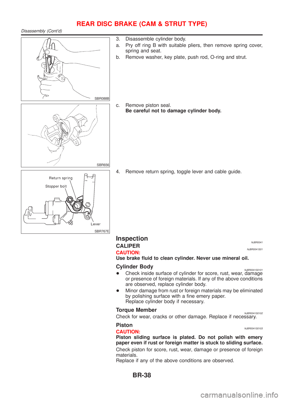
3. Disassemble cylinder body.
a. Pry off ring B with suitable pliers, then remove spring cover,
spring and seat.
b. Remove washer, key plate, push rod, O-ring and strut.
SBR656
c. Remove piston seal.
Be careful not to damage cylinder body.
SBR767E
4. Remove return spring, toggle lever and cable guide.
InspectionNJBR0041CALIPERNJBR0041S01CAUTION:
Use brake fluid to clean cylinder. Never use mineral oil.
Cylinder BodyNJBR0041S0101+Check inside surface of cylinder for score, rust, wear, damage
or presence of foreign materials. If any of the above conditions
are observed, replace cylinder body.
+Minor damage from rust or foreign materials may be eliminated
by polishing surface with a fine emery paper.
Replace cylinder body if necessary.
Torque MemberNJBR0041S0102Check for wear, cracks or other damage. Replace if necessary.
PistonNJBR0041S0103CAUTION:
Piston sliding surface is plated. Do not polish with emery
paper even if rust or foreign matter is stuck to sliding surface.
Check piston for score, rust, wear, damage or presence of foreign
materials.
Replace if any of the above conditions are observed.
REAR DISC BRAKE (CAM & STRUT TYPE)
Disassembly (Cont'd)
BR-38
Page 1343 of 2898
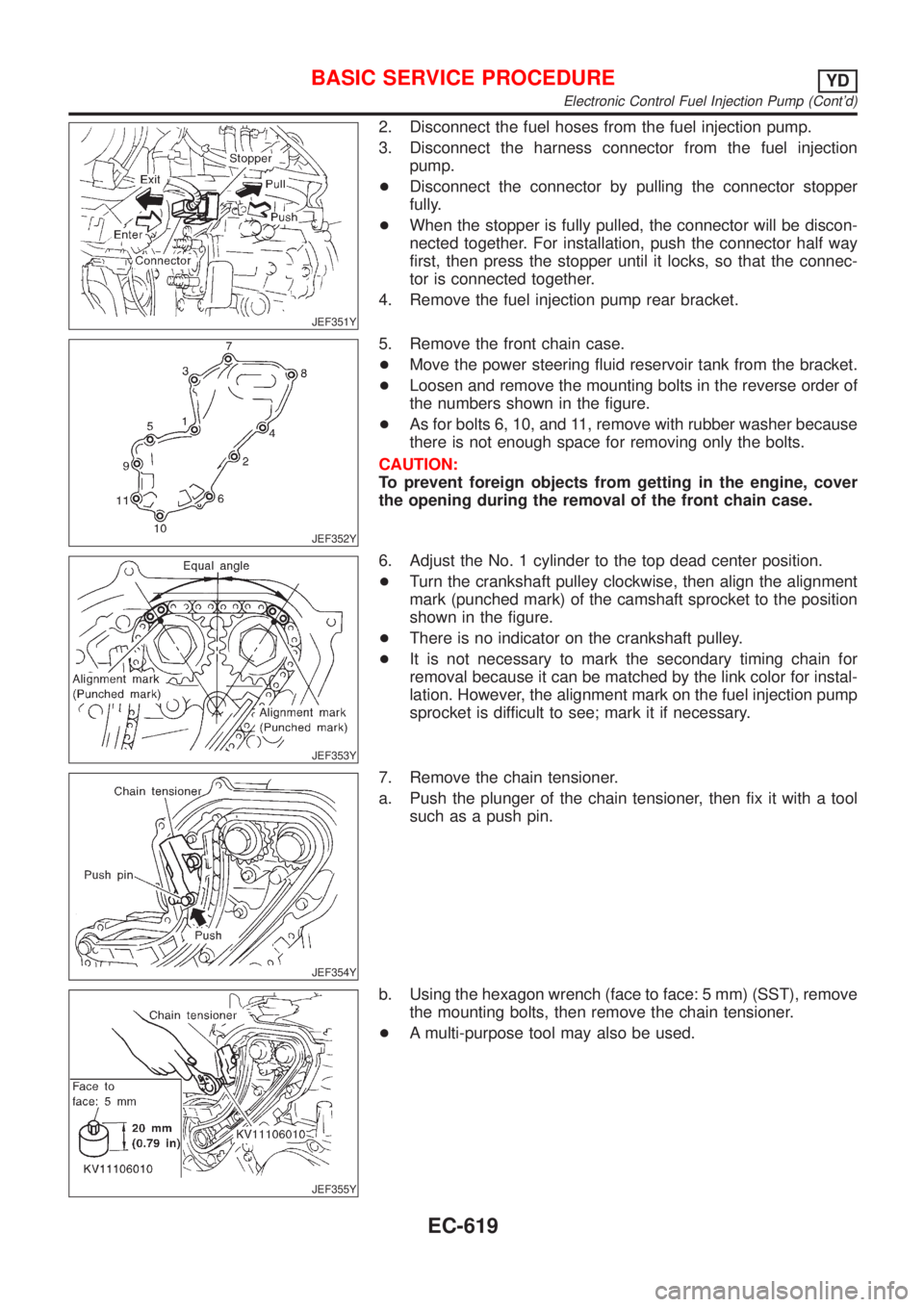
JEF351Y
2. Disconnect the fuel hoses from the fuel injection pump.
3. Disconnect the harness connector from the fuel injection
pump.
+Disconnect the connector by pulling the connector stopper
fully.
+When the stopper is fully pulled, the connector will be discon-
nected together. For installation, push the connector half way
first, then press the stopper until it locks, so that the connec-
tor is connected together.
4. Remove the fuel injection pump rear bracket.
JEF352Y
5. Remove the front chain case.
+Move the power steering fluid reservoir tank from the bracket.
+Loosen and remove the mounting bolts in the reverse order of
the numbers shown in the figure.
+As for bolts 6, 10, and 11, remove with rubber washer because
there is not enough space for removing only the bolts.
CAUTION:
To prevent foreign objects from getting in the engine, cover
the opening during the removal of the front chain case.
JEF353Y
6. Adjust the No. 1 cylinder to the top dead center position.
+Turn the crankshaft pulley clockwise, then align the alignment
mark (punched mark) of the camshaft sprocket to the position
shown in the figure.
+There is no indicator on the crankshaft pulley.
+It is not necessary to mark the secondary timing chain for
removal because it can be matched by the link color for instal-
lation. However, the alignment mark on the fuel injection pump
sprocket is difficult to see; mark it if necessary.
JEF354Y
7. Remove the chain tensioner.
a. Push the plunger of the chain tensioner, then fix it with a tool
such as a push pin.
JEF355Y
b. Using the hexagon wrench (face to face: 5 mm) (SST), remove
the mounting bolts, then remove the chain tensioner.
+A multi-purpose tool may also be used.
BASIC SERVICE PROCEDUREYD
Electronic Control Fuel Injection Pump (Cont'd)
EC-619
Page 1780 of 2898
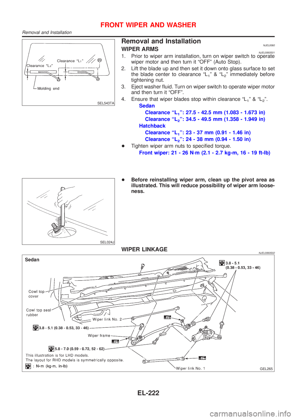
SEL543TA
Removal and InstallationNJEL0060WIPER ARMSNJEL0060S011. Prior to wiper arm installation, turn on wiper switch to operate
wiper motor and then turn it ªOFFº (Auto Stop).
2. Lift the blade up and then set it down onto glass surface to set
the blade center to clearance ªL
1º&ªL2º immediately before
tightening nut.
3. Eject washer fluid. Turn on wiper switch to operate wiper motor
and then turn it ªOFFº.
4. Ensure that wiper blades stop within clearance ªL
1º&ªL2º.
Sedan
Clearance ªL
1º: 27.5 - 42.5 mm (1.083 - 1.673 in)
Clearance ªL
2º: 34.5 - 49.5 mm (1.358 - 1.949 in)
Hatchback
Clearance ªL
1º: 23 - 37 mm (0.91 - 1.46 in)
Clearance ªL
2º: 24 - 38 mm (0.94 - 1.50 in)
+Tighten wiper arm nuts to specified torque.
Front wiper: 21 - 26 N´m (2.1 - 2.7 kg-m, 16 - 19 ft-lb)
SEL024J
+Before reinstalling wiper arm, clean up the pivot area as
illustrated. This will reduce possibility of wiper arm loose-
ness.
WIPER LINKAGENJEL0060S02
GEL265
FRONT WIPER AND WASHER
Removal and Installation
EL-222
Page 1787 of 2898
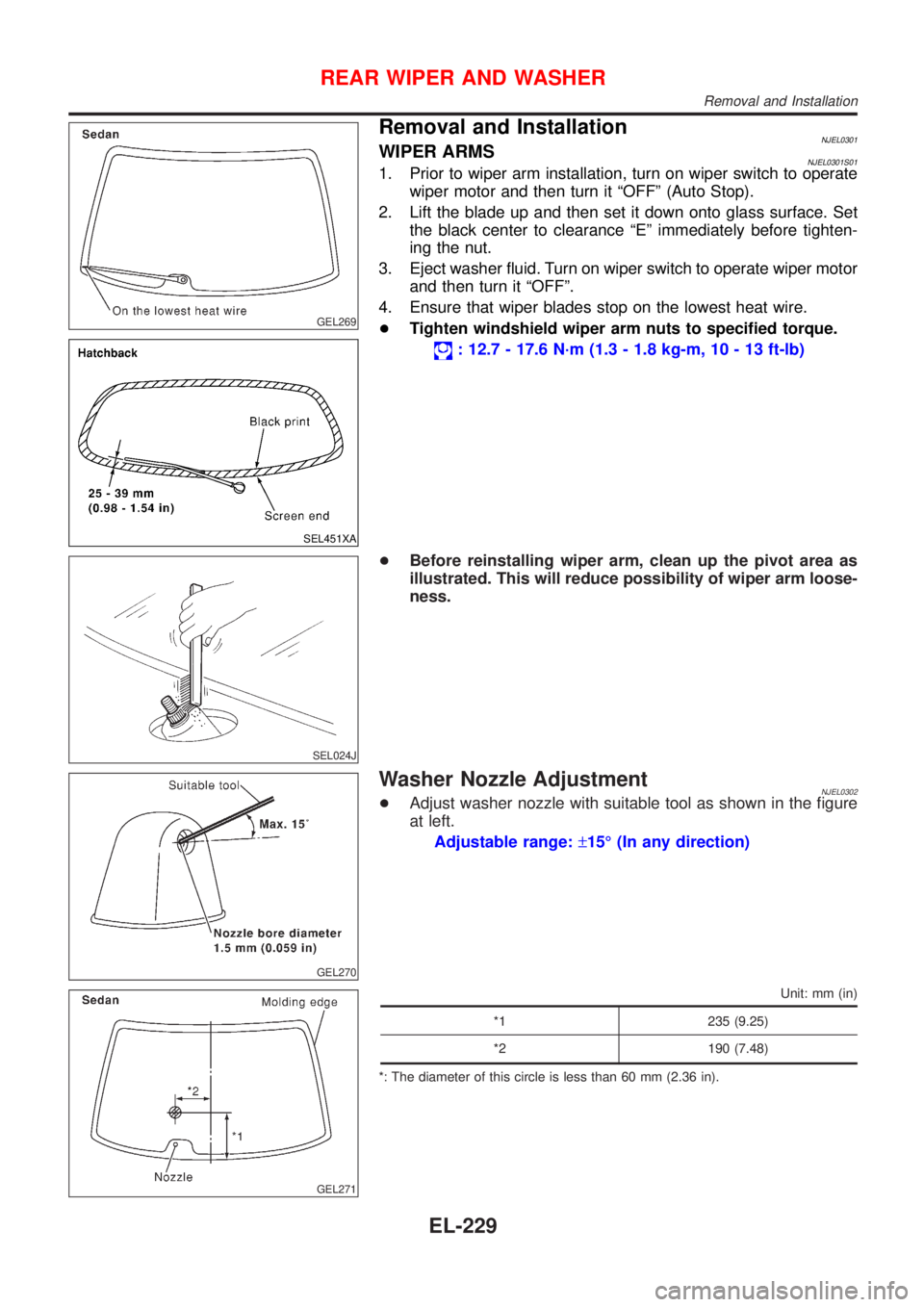
GEL269
SEL451XA
Removal and InstallationNJEL0301WIPER ARMSNJEL0301S011. Prior to wiper arm installation, turn on wiper switch to operate
wiper motor and then turn it ªOFFº (Auto Stop).
2. Lift the blade up and then set it down onto glass surface. Set
the black center to clearance ªEº immediately before tighten-
ing the nut.
3. Eject washer fluid. Turn on wiper switch to operate wiper motor
and then turn it ªOFFº.
4. Ensure that wiper blades stop on the lowest heat wire.
+Tighten windshield wiper arm nuts to specified torque.
: 12.7 - 17.6 N´m (1.3 - 1.8 kg-m, 10 - 13 ft-lb)
SEL024J
+Before reinstalling wiper arm, clean up the pivot area as
illustrated. This will reduce possibility of wiper arm loose-
ness.
GEL270
Washer Nozzle AdjustmentNJEL0302+Adjust washer nozzle with suitable tool as shown in the figure
at left.
Adjustable range:±15É (In any direction)
GEL271
Unit: mm (in)
*1 235 (9.25)
*2 190 (7.48)
*: The diameter of this circle is less than 60 mm (2.36 in).
REAR WIPER AND WASHER
Removal and Installation
EL-229
Page 2133 of 2898
NJEL0311
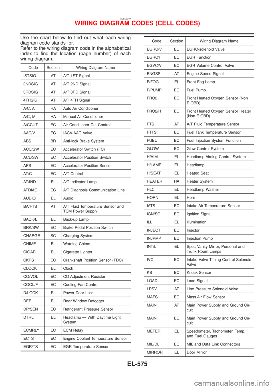
Use the chart below to find out what each wiring
diagram code stands for.
Refer to the wiring diagram code in the alphabetical
index to find the location (page number) of each
wiring diagram.
Code Section Wiring Diagram Name
ISTSIG AT A/T 1ST Signal
2NDSIG AT A/T 2ND Signal
3RDSIG AT A/T 3RD Signal
4THSIG AT A/T 4TH Signal
A/C, A HA Auto Air Conditioner
A/C, M HA Manual Air Conditioner
A/CCUT EC Air Conditioner Cut Control
AAC/V EC IACV-AAC Valve
ABS BR Anti-lock Brake System
ACC/SW EC Accelerator Switch (FC)
ACL/SW EC Accelerator Position Switch
APS EC Accelerator Position Sensor
AT/C EC A/T Control
AT/IND EL A/T Indicator Lamp
ATDIAG EC A/T Diagnosis Communication Line
AUDIO EL Audio
BA/FTS AT A/T Fluid Temperature Sensor and
TCM Power Supply
BACK/L EL Back-up Lamp
BRK/SW EC Brake Pedal Position Switch
CHARGE SC Charging System
CHIME EL Warning Chime
CIGAR EL Cigarette Lighter
CKPS EC Crankshaft Position Sensor (TDC)
CLOCK EL Clock
CO/VOL EC CO Adjustment Resistor
COOL/F EC Cooling Fan Control
D/LOCK EL Power Door Lock
DEF EL Rear Window Defogger
DP/SEN EC Refrigerant Pressure Sensor
DTRL EL Headlamp Ð With Daytime Light
System
ECMRLY EC ECM Relay
ECTS EC Engine Coolant Temperature Sensor
EGR/TS EC EGR Temperature Sensor
Code Section Wiring Diagram Name
EGRC/V EC EGRC-solenoid Valve
EGRC1 EC EGR Function
EGVC/V EC EGR Volume Control Valve
ENGSS AT Engine Speed Signal
F/FOG EL Front Fog Lamp
F/PUMP EC Fuel Pump
FRO2 EC Front Heated Oxygen Sensor (Non
E-OBD)
FRO2/H EC Front Heated Oxygen Sensor Heater
(Non E-OBD)
FTS AT A/T Fluid Temperature Sensor
FTTS EC Fuel Tank Temperature Sensor
FUEL EC Fuel Injection System Function
GLOW EC Glow Control System
H/AIM EL Headlamp Aiming Control System
H/LAMP EL Headlamp
H/SEAT EL Heated Seat
HEATER HA Heater System
HLC EL Headlamp Washer
HORN EL Horn
IATS EC Intake Air Temperature Sensor
IGN/SG EC Ignition Signal
ILL EL Illumination
INJECT EC Injector
INJPMP EC Injection Pump
INT/L EL Spot, Vanity Mirror, Personal and
Trunk Room Lamps
IVC EC Intake Valve Timing Control Solenoid
Valve
KS EC Knock Sensor
LOAD EC Load Signal
LPSV AT Line Pressure Solenoid Valve
MAFS EC Mass Air Flow Sensor
MAIN AT Main Power Supply and Ground Cir-
cuit
MAIN EC Main Power Supply and Ground Cir-
cuit
METER EL Speedometer, Tachometer, Temp.
and Fuel Gauges
MIL/DL EC MIL and Data Link Connectors
MIRROR EL Door Mirror
WIRING DIAGRAM CODES (CELL CODES)
EL-575
Page 2229 of 2898
JEM121G
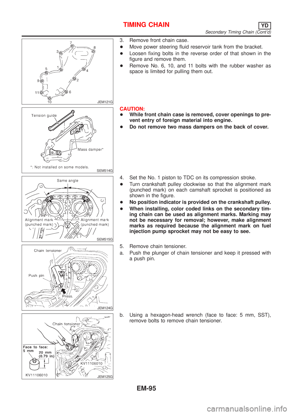
3. Remove front chain case.
+Move power steering fluid reservoir tank from the bracket.
+Loosen fixing bolts in the reverse order of that shown in the
figure and remove them.
+Remove No. 6, 10, and 11 bolts with the rubber washer as
space is limited for pulling them out.
SEM514G
CAUTION:
+While front chain case is removed, cover openings to pre-
vent entry of foreign material into engine.
+Do not remove two mass dampers on the back of cover.
SEM515G
4. Set the No. 1 piston to TDC on its compression stroke.
+Turn crankshaft pulley clockwise so that the alignment mark
(punched mark) on each camshaft sprocket is positioned as
shown in the figure.
+No position indicator is provided on the crankshaft pulley.
+When installing, color coded links on the secondary tim-
ing chain can be used as alignment marks. Marking may
not be necessary for removal; however, make alignment
marks as required because the alignment mark on fuel
injection pump sprocket may not be easy to see.
JEM124G
5. Remove chain tensioner.
a. Push the plunger of chain tensioner and keep it pressed with
a push pin.
JEM125G
b. Using a hexagon-head wrench (face to face: 5 mm, SST),
remove bolts to remove chain tensioner.
TIMING CHAINYD
Secondary Timing Chain (Cont'd)
EM-95
Page 2351 of 2898
SEF289H
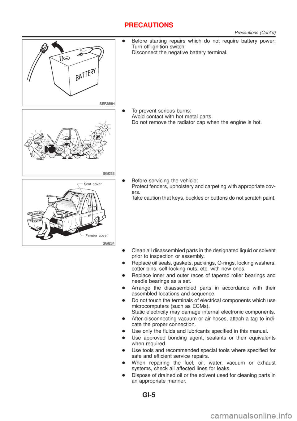
+Before starting repairs which do not require battery power:
Turn off ignition switch.
Disconnect the negative battery terminal.
SGI233
+To prevent serious burns:
Avoid contact with hot metal parts.
Do not remove the radiator cap when the engine is hot.
SGI234
+Before servicing the vehicle:
Protect fenders, upholstery and carpeting with appropriate cov-
ers.
Take caution that keys, buckles or buttons do not scratch paint.
+Clean all disassembled parts in the designated liquid or solvent
prior to inspection or assembly.
+Replace oil seals, gaskets, packings, O-rings, locking washers,
cotter pins, self-locking nuts, etc. with new ones.
+Replace inner and outer races of tapered roller bearings and
needle bearings as a set.
+Arrange the disassembled parts in accordance with their
assembled locations and sequence.
+Do not touch the terminals of electrical components which use
microcomputers (such as ECMs).
Static electricity may damage internal electronic components.
+After disconnecting vacuum or air hoses, attach a tag to indi-
cate the proper connection.
+Use only the fluids and lubricants specified in this manual.
+Use approved bonding agent, sealants or their equivalents
when required.
+Use tools and recommended special tools where specified for
safe and efficient service repairs.
+When repairing the fuel, oil, water, vacuum or exhaust
systems, check all affected lines for leaks.
+Dispose of drained oil or the solvent used for cleaning parts in
an appropriate manner.
PRECAUTIONS
Precautions (Cont'd)
GI-5