2001 NISSAN ALMERA ad blue
[x] Cancel search: ad bluePage 11 of 2898

parts. Apply petroleum jelly to protect O-rings and seals, or
hold bearings and washers in place during assembly. Do not
use grease.
+Extreme care should be taken to avoid damage to O-rings,
seals and gaskets when assembling.
+After overhaul, refill the transaxle with new ATF.
+When the A/T drain plug is removed, only some of the fluid is
drained. Old A/T fluid will remain in torque converter and ATF
cooling system.
Always follow the procedures under ªChanging A/T Fluidº in the
AT section when changing A/T fluid. Refer to ªChanging A/T
Fluidº, AT-15.
Service Notice or PrecautionsNJAT0247FAIL-SAFENJAT0247S01The TCM has an electronic Fail-Safe (limp home mode). This allows the vehicle to be driven even if a major
electrical input/output device circuit is damaged.
Under Fail-Safe, the vehicle always runs in third gear, even with a shift lever position of ª1º, ª2º or ªDº. The
customer may complain of sluggish or poor acceleration.
When the ignition key is turned ªONº following Fail-Safe operation, O/D OFF indicator lamp blinks for about
8 seconds. (For GENERAL AND EXCEPT FOR EURO-OBD; ªSELF-DIAGNOSTIC PROCEDURE (WITHOUT
CONSULT-II)º, refer to AT-44 and for EURO-OBD; ªTCM SELF-DIAGNOSTIC PROCEDURE (No Tools)º, refer
to AT-63.)
Fail-Safe may occur without electrical circuit damage if the vehicle is driven under extreme conditions (such
as excessive wheel spin followed by sudden braking). To recover normal shift pattern, turn the ignition key
ªOFFº for 5 seconds, then ªONº.
The blinking of the O/D OFF indicator lamp for about 8 seconds will appear only once and be cleared. The
customer may resume normal driving conditions.
Always follow the ªWORK FLOWº [Refer to AT-73 (General and except for Euro-OBD), AT-78 (EURO-OBD).]
The SELF-DIAGNOSIS results will be as follows:
The first SELF-DIAGNOSIS will indicate damage to the vehicle speed sensor or the revolution sensor.
During the next SELF-DIAGNOSIS, performed after checking the sensor, no damages will be indicated.
TORQUE CONVERTER SERVICENJAT0247S02The torque converter should be replaced under any of the following conditions:
+External leaks in the hub weld area.
+Converter hub is scored or damaged.
+Converter pilot is broken, damaged or fits poorly into crankshaft.
+Steel particles are found after flushing the cooler and cooler lines.
+Pump is damaged or steel particles are found in the converter.
+Vehicle has TCC shudder and/or no TCC apply. Replace only after all hydraulic and electrical diagnoses
have been made. (Converter clutch material may be glazed.)
+Converter is contaminated with engine coolant containing antifreeze.
+Internal failure of stator roller clutch.
+Heavy clutch debris due to overheating (blue converter).
+Steel particles or clutch lining material found in fluid filter or on magnet when no internal parts in unit are
worn or damaged Ð indicates that lining material came from converter.
PRECAUTIONS
Precautions (Cont'd)
AT-9
Page 2194 of 2898
SEM588A
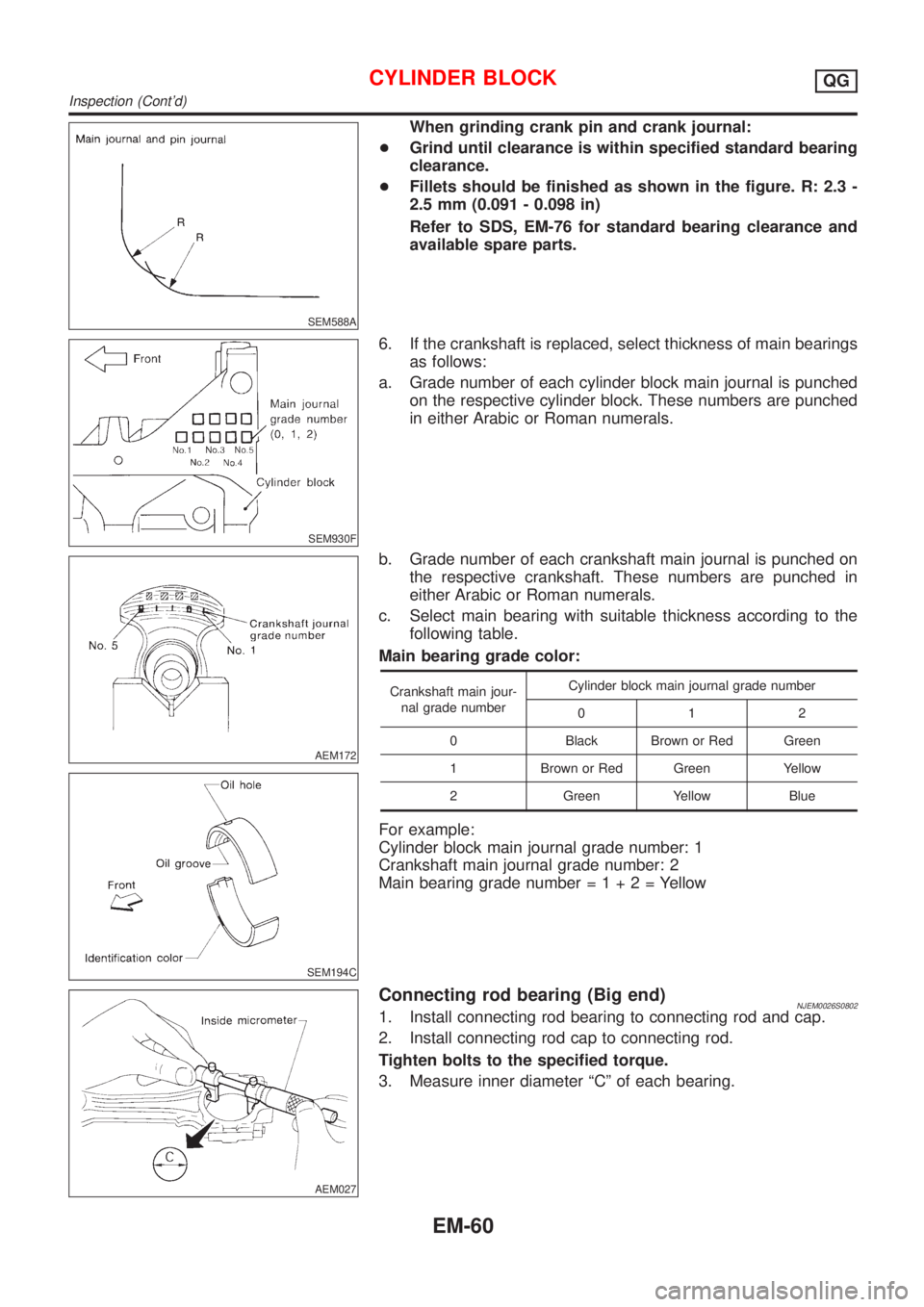
When grinding crank pin and crank journal:
+Grind until clearance is within specified standard bearing
clearance.
+Fillets should be finished as shown in the figure. R: 2.3 -
2.5 mm (0.091 - 0.098 in)
Refer to SDS, EM-76 for standard bearing clearance and
available spare parts.
SEM930F
6. If the crankshaft is replaced, select thickness of main bearings
as follows:
a. Grade number of each cylinder block main journal is punched
on the respective cylinder block. These numbers are punched
in either Arabic or Roman numerals.
AEM172
SEM194C
b. Grade number of each crankshaft main journal is punched on
the respective crankshaft. These numbers are punched in
either Arabic or Roman numerals.
c. Select main bearing with suitable thickness according to the
following table.
Main bearing grade color:
Crankshaft main jour-
nal grade numberCylinder block main journal grade number
012
0 Black Brown or Red Green
1 Brown or Red Green Yellow
2 Green Yellow Blue
For example:
Cylinder block main journal grade number: 1
Crankshaft main journal grade number: 2
Main bearing grade number=1+2=Yellow
AEM027
Connecting rod bearing (Big end)NJEM0026S08021. Install connecting rod bearing to connecting rod and cap.
2. Install connecting rod cap to connecting rod.
Tighten bolts to the specified torque.
3. Measure inner diameter ªCº of each bearing.
CYLINDER BLOCKQG
Inspection (Cont'd)
EM-60
Page 2209 of 2898
![NISSAN ALMERA 2001 Service Manual Connecting RodNJEM0035Unit: mm (in)
Center distance140.45 - 140.55 (5.5295 - 5.5335)
Bend limit [per 100 (3.94)]0.15 (0.0059)
Torsion limit [per 100 (3.94)]0.3 (0.012)
Connecting rod bushing inner dia NISSAN ALMERA 2001 Service Manual Connecting RodNJEM0035Unit: mm (in)
Center distance140.45 - 140.55 (5.5295 - 5.5335)
Bend limit [per 100 (3.94)]0.15 (0.0059)
Torsion limit [per 100 (3.94)]0.3 (0.012)
Connecting rod bushing inner dia](/manual-img/5/57348/w960_57348-2208.png)
Connecting RodNJEM0035Unit: mm (in)
Center distance140.45 - 140.55 (5.5295 - 5.5335)
Bend limit [per 100 (3.94)]0.15 (0.0059)
Torsion limit [per 100 (3.94)]0.3 (0.012)
Connecting rod bushing inner diameter* (small end) 19.000 - 19.012 (0.7480 - 0.7485)
Connecting rod big end inner diameter 43.000 - 43.013 (1.6929 - 1.6934)
Side clearanceStandard 0.200 - 0.470 (0.0079 - 0.0185)
Limit 0.5 (0.020)
*After installing in connecting rod
CrankshaftNJEM0036Unit: mm (in)
Main journal dia. ªDmºGrade No. 0 49.956 - 49.964 (1.9668 - 1.9671)
Grade No. 1 49.948 - 49.956 (1.9665 - 1.9668)
Grade No. 2 49.940 - 49.948 (1.9661 - 1.9665)
Pin journal dia. ªDpºGrade No. 0 39.968 - 39.974 (1.5735 - 1.5738)
Grade No. 1 39.962 - 39.968 (1.5733 - 1.5735)
Grade No. 2 39.956 - 39.962 (1.5731 - 1.5733)
Center distance ªrº43.95 - 44.05 (1.7303 - 1.7342)
Out-of-round (X þ Y)Standard Less than 0.003 (0.0001)
Limit Less than 0.005 (0.0002)
Taper (A þ B)Standard Less than 0.004 (0.0002)
Limit Less than 0.005 (0.0002)
Runout [TIR*]Standard Less than 0.04 (0.0016)
Limit Less than 0.05 (0.0020)
Free end playStandard 0.060 - 0.220 (0.0024 - 0.0087)
Limit 0.3 (0.012)
*: Total indicator reading
Main BearingNJEM0037STANDARDNJEM0037S01
Grade No. Thickness ªTº mm (in) Identification color
0 1.826 - 1.830 (0.0719 - 0.0720) Black
1 1.830 - 1.834 (0.0720 - 0.0722) Brown or Red
2 1.834 - 1.838 (0.0722 - 0.0724) Green
3 1.838 - 1.842 (0.0724 - 0.0725) Yellow
4 1.842 - 1.846 (0.0725 - 0.0727) Blue
UNDERSIZENJEM0037S02Unit: mm (in)
Thickness ªTº
0.25 (0.0098) 1.960 - 1.964 (0.0772 - 0.0773)
0.50 (0.0197) 2.085 - 2.089 (0.0821 - 0.0822)
SERVICE DATA AND SPECIFICATIONS (SDS)QG
Connecting Rod
EM-75
Page 2284 of 2898
JEM208G
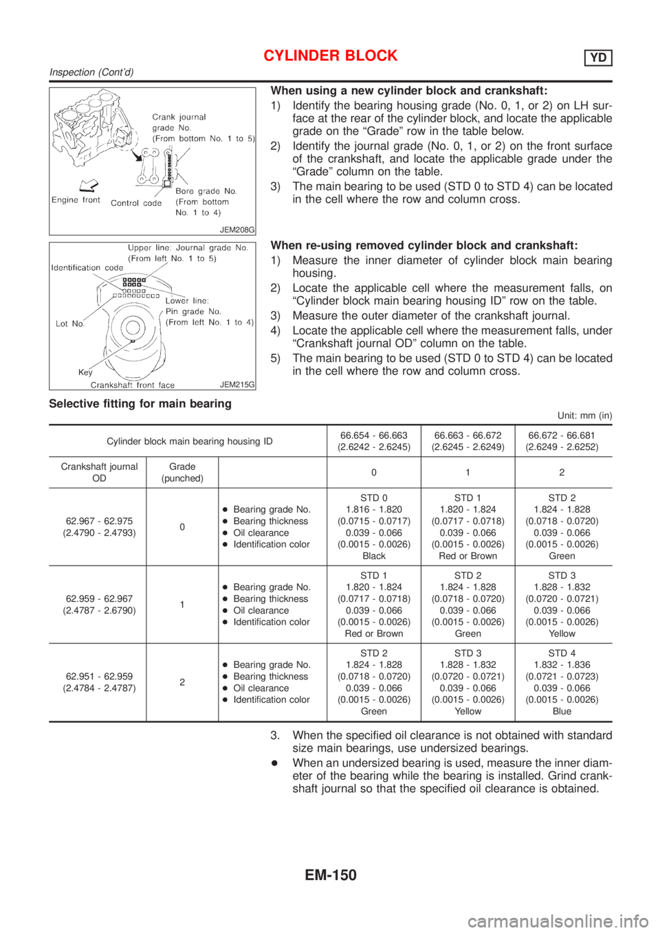
When using a new cylinder block and crankshaft:
1) Identify the bearing housing grade (No. 0, 1, or 2) on LH sur-
face at the rear of the cylinder block, and locate the applicable
grade on the ªGradeº row in the table below.
2) Identify the journal grade (No. 0, 1, or 2) on the front surface
of the crankshaft, and locate the applicable grade under the
ªGradeº column on the table.
3) The main bearing to be used (STD 0 to STD 4) can be located
in the cell where the row and column cross.
JEM215G
When re-using removed cylinder block and crankshaft:
1) Measure the inner diameter of cylinder block main bearing
housing.
2) Locate the applicable cell where the measurement falls, on
ªCylinder block main bearing housing IDº row on the table.
3) Measure the outer diameter of the crankshaft journal.
4) Locate the applicable cell where the measurement falls, under
ªCrankshaft journal ODº column on the table.
5) The main bearing to be used (STD 0 to STD 4) can be located
in the cell where the row and column cross.
Selective fitting for main bearing
Unit: mm (in)
Cylinder block main bearing housing ID66.654 - 66.663
(2.6242 - 2.6245)66.663 - 66.672
(2.6245 - 2.6249)66.672 - 66.681
(2.6249 - 2.6252)
Crankshaft journal
ODGrade
(punched)012
62.967 - 62.975
(2.4790 - 2.4793)0+Bearing grade No.
+Bearing thickness
+Oil clearance
+Identification colorSTD 0
1.816 - 1.820
(0.0715 - 0.0717)
0.039 - 0.066
(0.0015 - 0.0026)
BlackSTD 1
1.820 - 1.824
(0.0717 - 0.0718)
0.039 - 0.066
(0.0015 - 0.0026)
Red or BrownSTD 2
1.824 - 1.828
(0.0718 - 0.0720)
0.039 - 0.066
(0.0015 - 0.0026)
Green
62.959 - 62.967
(2.4787 - 2.6790)1+Bearing grade No.
+Bearing thickness
+Oil clearance
+Identification colorSTD 1
1.820 - 1.824
(0.0717 - 0.0718)
0.039 - 0.066
(0.0015 - 0.0026)
Red or BrownSTD 2
1.824 - 1.828
(0.0718 - 0.0720)
0.039 - 0.066
(0.0015 - 0.0026)
GreenSTD 3
1.828 - 1.832
(0.0720 - 0.0721)
0.039 - 0.066
(0.0015 - 0.0026)
Yellow
62.951 - 62.959
(2.4784 - 2.4787)2+Bearing grade No.
+Bearing thickness
+Oil clearance
+Identification colorSTD 2
1.824 - 1.828
(0.0718 - 0.0720)
0.039 - 0.066
(0.0015 - 0.0026)
GreenSTD 3
1.828 - 1.832
(0.0720 - 0.0721)
0.039 - 0.066
(0.0015 - 0.0026)
YellowSTD 4
1.832 - 1.836
(0.0721 - 0.0723)
0.039 - 0.066
(0.0015 - 0.0026)
Blue
3. When the specified oil clearance is not obtained with standard
size main bearings, use undersized bearings.
+When an undersized bearing is used, measure the inner diam-
eter of the bearing while the bearing is installed. Grind crank-
shaft journal so that the specified oil clearance is obtained.
CYLINDER BLOCKYD
Inspection (Cont'd)
EM-150
Page 2303 of 2898
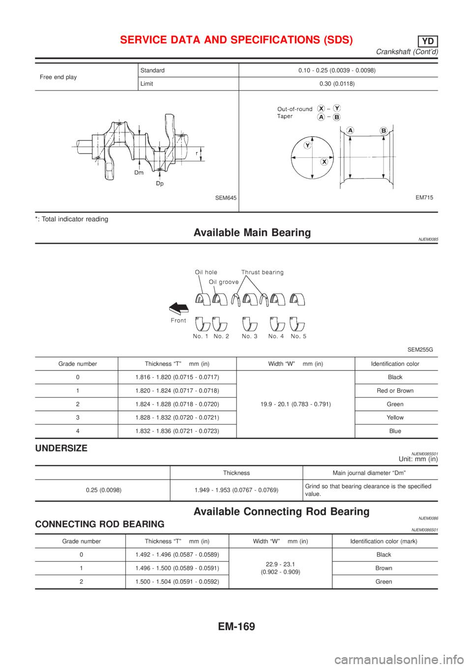
Free end playStandard 0.10 - 0.25 (0.0039 - 0.0098)
Limit 0.30 (0.0118)
SEM645EM715
*: Total indicator reading
Available Main BearingNJEM0085
SEM255G
Grade number Thickness ªTº mm (in) Width ªWº mm (in) Identification color
0 1.816 - 1.820 (0.0715 - 0.0717)
19.9 - 20.1 (0.783 - 0.791)Black
1 1.820 - 1.824 (0.0717 - 0.0718) Red or Brown
2 1.824 - 1.828 (0.0718 - 0.0720) Green
3 1.828 - 1.832 (0.0720 - 0.0721) Yellow
4 1.832 - 1.836 (0.0721 - 0.0723) Blue
UNDERSIZENJEM0085S01Unit: mm (in)
Thickness Main journal diameter ªDmº
0.25 (0.0098) 1.949 - 1.953 (0.0767 - 0.0769)Grind so that bearing clearance is the specified
value.
Available Connecting Rod BearingNJEM0086CONNECTING ROD BEARINGNJEM0086S01
Grade number Thickness ªTº mm (in) Width ªWº mm (in) Identification color (mark)
0 1.492 - 1.496 (0.0587 - 0.0589)
22.9 - 23.1
(0.902 - 0.909)Black
1 1.496 - 1.500 (0.0589 - 0.0591) Brown
2 1.500 - 1.504 (0.0591 - 0.0592) Green
SERVICE DATA AND SPECIFICATIONS (SDS)YD
Crankshaft (Cont'd)
EM-169
Page 2359 of 2898
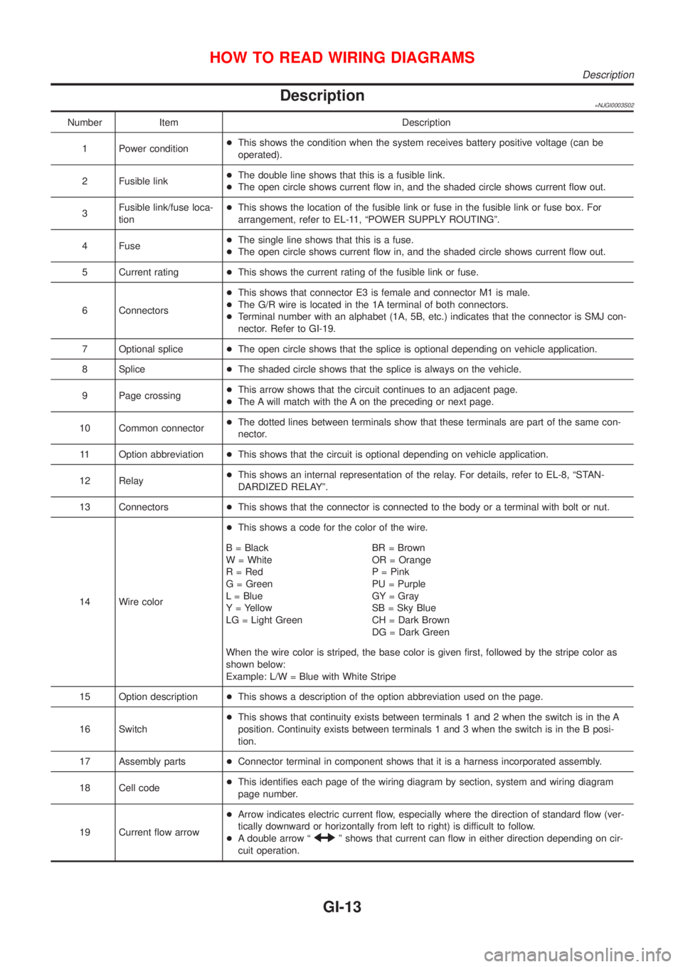
Description=NJGI0003S02
Number Item Description
1 Power condition+This shows the condition when the system receives battery positive voltage (can be
operated).
2 Fusible link+The double line shows that this is a fusible link.
+The open circle shows current flow in, and the shaded circle shows current flow out.
3Fusible link/fuse loca-
tion+This shows the location of the fusible link or fuse in the fusible link or fuse box. For
arrangement, refer to EL-11, ªPOWER SUPPLY ROUTINGº.
4 Fuse+The single line shows that this is a fuse.
+The open circle shows current flow in, and the shaded circle shows current flow out.
5 Current rating+This shows the current rating of the fusible link or fuse.
6 Connectors+This shows that connector E3 is female and connector M1 is male.
+The G/R wire is located in the 1A terminal of both connectors.
+Terminal number with an alphabet (1A, 5B, etc.) indicates that the connector is SMJ con-
nector. Refer to GI-19.
7 Optional splice+The open circle shows that the splice is optional depending on vehicle application.
8 Splice+The shaded circle shows that the splice is always on the vehicle.
9 Page crossing+This arrow shows that the circuit continues to an adjacent page.
+The A will match with the A on the preceding or next page.
10 Common connector+The dotted lines between terminals show that these terminals are part of the same con-
nector.
11 Option abbreviation+This shows that the circuit is optional depending on vehicle application.
12 Relay+This shows an internal representation of the relay. For details, refer to EL-8, ªSTAN-
DARDIZED RELAYº.
13 Connectors+This shows that the connector is connected to the body or a terminal with bolt or nut.
14 Wire color+This shows a code for the color of the wire.
B = Black
W = White
R = Red
G = Green
L = Blue
Y = Yellow
LG = Light GreenBR = Brown
OR = Orange
P = Pink
PU = Purple
GY = Gray
SB = Sky Blue
CH = Dark Brown
DG = Dark Green
When the wire color is striped, the base color is given first, followed by the stripe color as
shown below:
Example: L/W = Blue with White Stripe
15 Option description+This shows a description of the option abbreviation used on the page.
16 Switch+This shows that continuity exists between terminals 1 and 2 when the switch is in the A
position. Continuity exists between terminals 1 and 3 when the switch is in the B posi-
tion.
17 Assembly parts+Connector terminal in component shows that it is a harness incorporated assembly.
18 Cell code+This identifies each page of the wiring diagram by section, system and wiring diagram
page number.
19 Current flow arrow+Arrow indicates electric current flow, especially where the direction of standard flow (ver-
tically downward or horizontally from left to right) is difficult to follow.
+A double arrow ª
º shows that current can flow in either direction depending on cir-
cuit operation.
HOW TO READ WIRING DIAGRAMS
Description
GI-13
Page 2411 of 2898
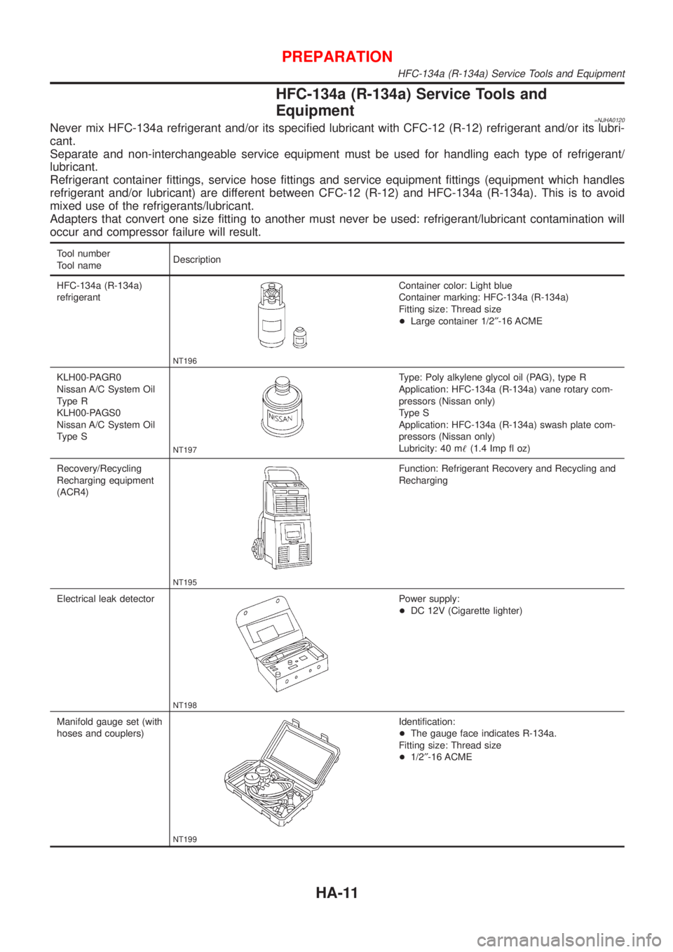
HFC-134a (R-134a) Service Tools and
Equipment
=NJHA0120Never mix HFC-134a refrigerant and/or its specified lubricant with CFC-12 (R-12) refrigerant and/or its lubri-
cant.
Separate and non-interchangeable service equipment must be used for handling each type of refrigerant/
lubricant.
Refrigerant container fittings, service hose fittings and service equipment fittings (equipment which handles
refrigerant and/or lubricant) are different between CFC-12 (R-12) and HFC-134a (R-134a). This is to avoid
mixed use of the refrigerants/lubricant.
Adapters that convert one size fitting to another must never be used: refrigerant/lubricant contamination will
occur and compressor failure will result.
Tool number
Tool nameDescription
HFC-134a (R-134a)
refrigerant
NT196
Container color: Light blue
Container marking: HFC-134a (R-134a)
Fitting size: Thread size
+Large container 1/2²-16 ACME
KLH00-PAGR0
Nissan A/C System Oil
Type R
KLH00-PAGS0
Nissan A/C System Oil
Type S
NT197
Type: Poly alkylene glycol oil (PAG), type R
Application: HFC-134a (R-134a) vane rotary com-
pressors (Nissan only)
Type S
Application: HFC-134a (R-134a) swash plate com-
pressors (Nissan only)
Lubricity: 40 m!(1.4 Imp fl oz)
Recovery/Recycling
Recharging equipment
(ACR4)
NT195
Function: Refrigerant Recovery and Recycling and
Recharging
Electrical leak detector
NT198
Power supply:
+DC 12V (Cigarette lighter)
Manifold gauge set (with
hoses and couplers)
NT199
Identification:
+The gauge face indicates R-134a.
Fitting size: Thread size
+1/2²-16 ACME
PREPARATION
HFC-134a (R-134a) Service Tools and Equipment
HA-11
Page 2412 of 2898
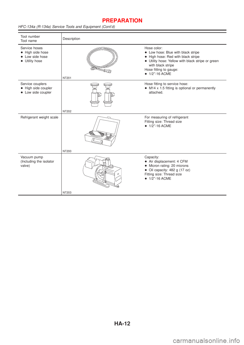
Tool number
Tool nameDescription
Service hoses
+High side hose
+Low side hose
+Utility hose
NT201
Hose color:
+Low hose: Blue with black stripe
+High hose: Red with black stripe
+Utility hose: Yellow with black stripe or green
with black stripe
Hose fitting to gauge:
+1/2²-16 ACME
Service couplers
+High side coupler
+Low side coupler
NT202
Hose fitting to service hose:
+M14 x 1.5 fitting is optional or permanently
attached.
Refrigerant weight scale
NT200
For measuring of refrigerant
Fitting size: Thread size
+1/2²-16 ACME
Vacuum pump
(Including the isolator
valve)
NT203
Capacity:
+Air displacement: 4 CFM
+Micron rating: 20 microns
+Oil capacity: 482 g (17 oz)
Fitting size: Thread size
+1/2²-16 ACME
PREPARATION
HFC-134a (R-134a) Service Tools and Equipment (Cont'd)
HA-12