2001 NISSAN ALMERA fuel tank removal
[x] Cancel search: fuel tank removalPage 1343 of 2898
JEF351Y
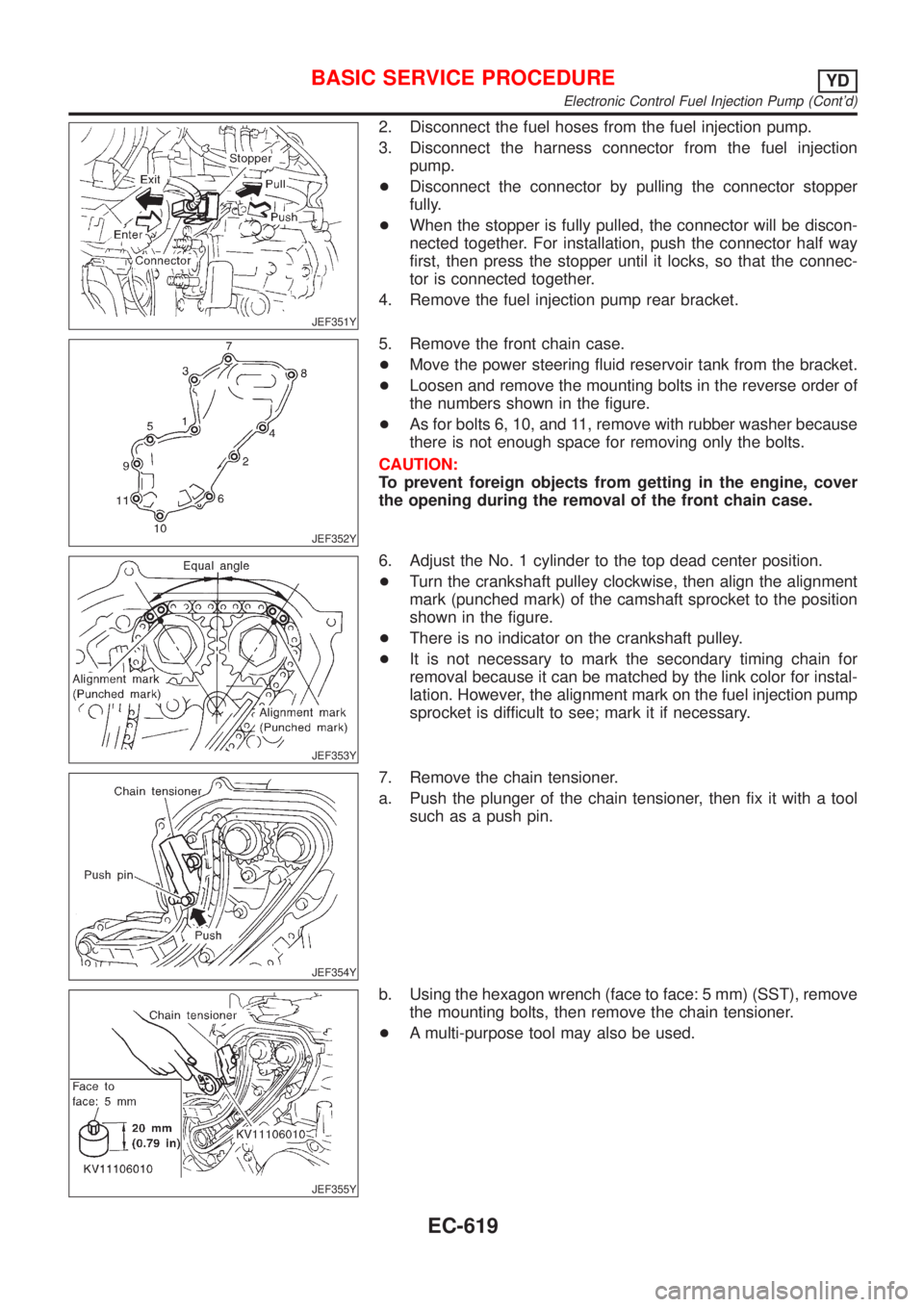
2. Disconnect the fuel hoses from the fuel injection pump.
3. Disconnect the harness connector from the fuel injection
pump.
+Disconnect the connector by pulling the connector stopper
fully.
+When the stopper is fully pulled, the connector will be discon-
nected together. For installation, push the connector half way
first, then press the stopper until it locks, so that the connec-
tor is connected together.
4. Remove the fuel injection pump rear bracket.
JEF352Y
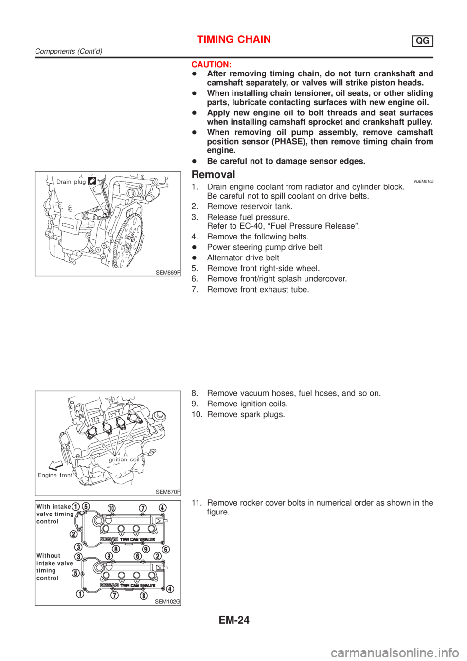
5. Remove the front chain case.
+Move the power steering fluid reservoir tank from the bracket.
+Loosen and remove the mounting bolts in the reverse order of
the numbers shown in the figure.
+As for bolts 6, 10, and 11, remove with rubber washer because
there is not enough space for removing only the bolts.
CAUTION:
To prevent foreign objects from getting in the engine, cover
the opening during the removal of the front chain case.
JEF353Y
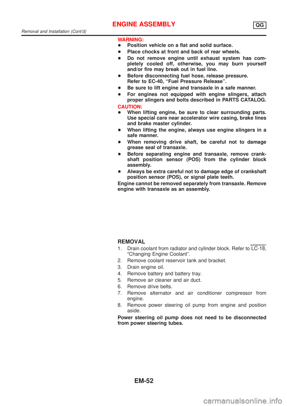
6. Adjust the No. 1 cylinder to the top dead center position.
+Turn the crankshaft pulley clockwise, then align the alignment
mark (punched mark) of the camshaft sprocket to the position
shown in the figure.
+There is no indicator on the crankshaft pulley.
+It is not necessary to mark the secondary timing chain for
removal because it can be matched by the link color for instal-
lation. However, the alignment mark on the fuel injection pump
sprocket is difficult to see; mark it if necessary.
JEF354Y
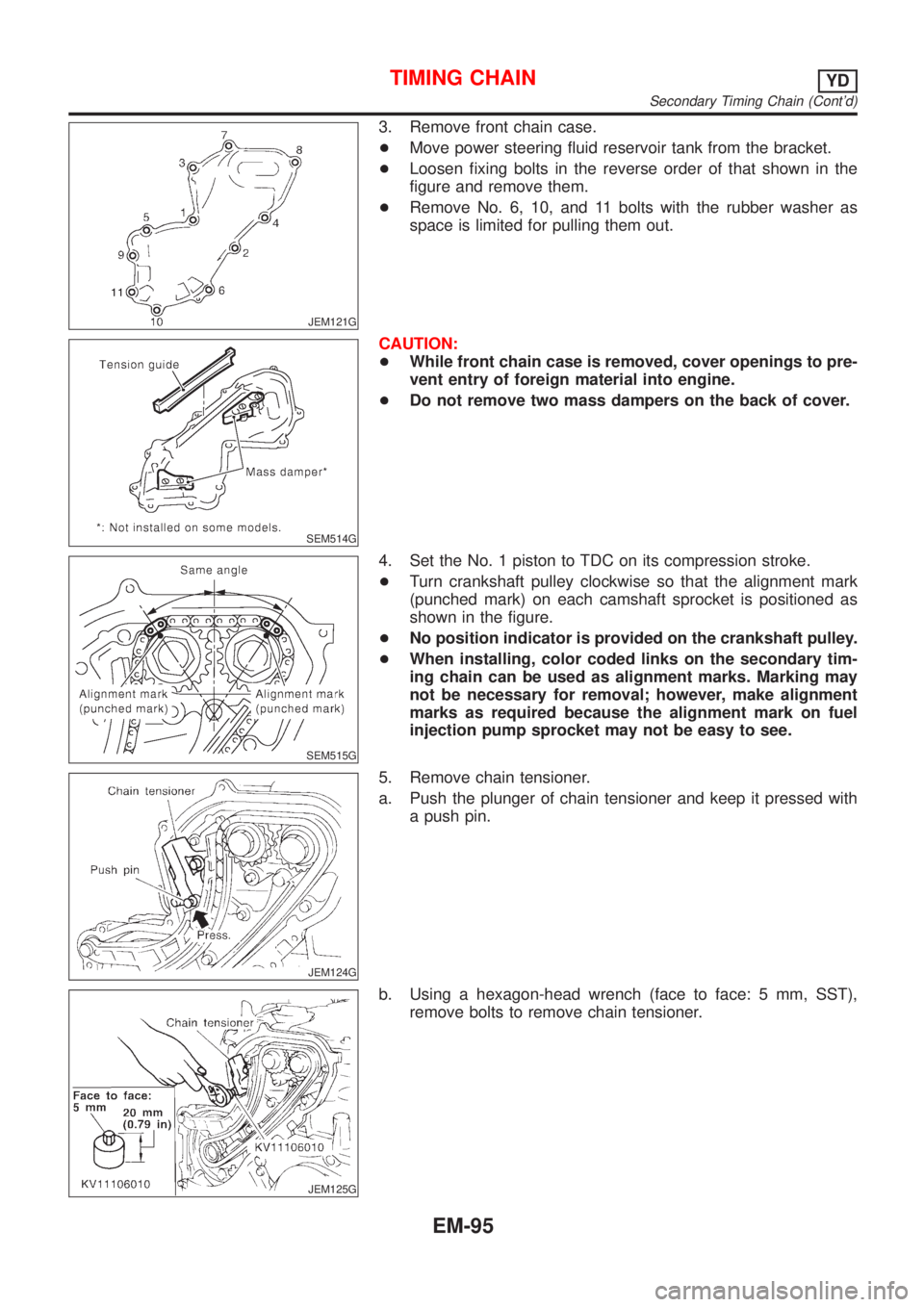
7. Remove the chain tensioner.
a. Push the plunger of the chain tensioner, then fix it with a tool
such as a push pin.
JEF355Y
b. Using the hexagon wrench (face to face: 5 mm) (SST), remove
the mounting bolts, then remove the chain tensioner.
+A multi-purpose tool may also be used.
BASIC SERVICE PROCEDUREYD
Electronic Control Fuel Injection Pump (Cont'd)
EC-619
Page 2158 of 2898
CAUTION:
+After removing timing chain, do not turn crankshaft and
camshaft separately, or valves will strike piston heads.
+When installing chain tensioner, oil seats, or other sliding
parts, lubricate contacting surfaces with new engine oil.
+Apply new engine oil to bolt threads and seat surfaces
when installing camshaft sprocket and crankshaft pulley.
+When removing oil pump assembly, remove camshaft
position sensor (PHASE), then remove timing chain from
engine.
+Be careful not to damage sensor edges.
SEM869F
RemovalNJEM01051. Drain engine coolant from radiator and cylinder block.
Be careful not to spill coolant on drive belts.
2. Remove reservoir tank.
3. Release fuel pressure.
Refer to EC-40, ªFuel Pressure Releaseº.
4. Remove the following belts.
+Power steering pump drive belt
+Alternator drive belt
5. Remove front right-side wheel.
6. Remove front/right splash undercover.
7. Remove front exhaust tube.
SEM870F
8. Remove vacuum hoses, fuel hoses, and so on.
9. Remove ignition coils.
10. Remove spark plugs.
SEM102G
11. Remove rocker cover bolts in numerical order as shown in the
figure.
TIMING CHAINQG
Components (Cont'd)
EM-24
Page 2186 of 2898
WARNING:
+Position vehicle on a flat and solid surface.
+Place chocks at front and back of rear wheels.
+Do not remove engine until exhaust system has com-
pletely cooled off, otherwise, you may burn yourself
and/or fire may break out in fuel line.
+Before disconnecting fuel hose, release pressure.
Refer to EC-40, ªFuel Pressure Releaseº.
+Be sure to lift engine and transaxle in a safe manner.
+For engines not equipped with engine slingers, attach
proper slingers and bolts described in PARTS CATALOG.
CAUTION:
+When lifting engine, be sure to clear surrounding parts.
Use special care near accelerator wire casing, brake lines
and brake master cylinder.
+When lifting the engine, always use engine slingers in a
safe manner.
+When removing drive shaft, be careful not to damage
grease seal of transaxle.
+Before separating engine and transaxle, remove crank-
shaft position sensor (POS) from the cylinder block
assembly.
+Always be extra careful not to damage edge of crankshaft
position sensor (POS), or signal plate teeth.
Engine cannot be removed separately from transaxle. Remove
engine with transaxle as an assembly.
REMOVALNJEM0022S011. Drain coolant from radiator and cylinder block. Refer to LC-18,
ªChanging Engine Coolantº.
2. Remove coolant reservoir tank and bracket.
3. Drain engine oil.
4. Remove battery and battery tray.
5. Remove air cleaner and air duct.
6. Remove drive belts.
7. Remove alternator and air conditioner compressor from
engine.
8. Remove power steering oil pump from engine and position
aside.
Power steering oil pump does not need to be disconnected
from power steering tubes.
ENGINE ASSEMBLYQG
Removal and Installation (Cont'd)
EM-52
Page 2229 of 2898
JEM121G
3. Remove front chain case.
+Move power steering fluid reservoir tank from the bracket.
+Loosen fixing bolts in the reverse order of that shown in the
figure and remove them.
+Remove No. 6, 10, and 11 bolts with the rubber washer as
space is limited for pulling them out.
SEM514G
CAUTION:
+While front chain case is removed, cover openings to pre-
vent entry of foreign material into engine.
+Do not remove two mass dampers on the back of cover.
SEM515G
4. Set the No. 1 piston to TDC on its compression stroke.
+Turn crankshaft pulley clockwise so that the alignment mark
(punched mark) on each camshaft sprocket is positioned as
shown in the figure.
+No position indicator is provided on the crankshaft pulley.
+When installing, color coded links on the secondary tim-
ing chain can be used as alignment marks. Marking may
not be necessary for removal; however, make alignment
marks as required because the alignment mark on fuel
injection pump sprocket may not be easy to see.
JEM124G
5. Remove chain tensioner.
a. Push the plunger of chain tensioner and keep it pressed with
a push pin.
JEM125G
b. Using a hexagon-head wrench (face to face: 5 mm, SST),
remove bolts to remove chain tensioner.
TIMING CHAINYD
Secondary Timing Chain (Cont'd)
EM-95
Page 2305 of 2898
ACCELERATOR CONTROL, FUEL &
EXHAUST SYSTEMS
SECTION
FE
CONTENTS
QG
PREPARATION...............................................................2
Special Service Tools ..................................................2
Commercial Service Tools ...........................................2
ACCELERATOR CONTROL SYSTEM...........................3
Removal and Installation .............................................3
Adjusting Accelerator Wire ..........................................3
MODELS WITH THROTTLE OPENER.........................3
MODELS WITHOUT THROTTLE OPENER..................4
FUEL SYSTEM................................................................5
Checking Fuel Lines ....................................................5
Removal and Installation .............................................5
Fuel Tank .....................................................................6
REMOVAL.................................................................7
INSTALLATION........................................................ 11
Fuel Pump, Fuel Level Sensor Unit and Fuel
Filter ...........................................................................12
REMOVAL...............................................................12
INSTALLATION........................................................14
EXHAUST SYSTEM......................................................15
Checking Exhaust System.........................................15
Removal and Installation ...........................................15
YD
PREPARATION.............................................................18
Special Service Tool ..................................................18Commercial Service Tool ...........................................18
ACCELERATOR CONTROL SYSTEM.........................19
Removal and Installation ...........................................19
Inspection...................................................................19
FUEL SYSTEM..............................................................20
Checking Fuel Lines ..................................................20
Water Draining from Fuel Filter .................................20
DRAINING WATER..................................................20
FUEL FILTER CHECK..............................................20
Changing Fuel Filter ..................................................20
REMOVAL...............................................................20
INSTALLATION........................................................21
Bleeding Fuel Filter....................................................21
Checking Priming Pump ............................................21
Checking Water in Fuel Filter Sensor (where
fitted) ..........................................................................22
Removal and Installation ...........................................22
Fuel Tank ...................................................................23
REMOVAL...............................................................25
INSTALLATION........................................................28
Fuel Level Sensor Unit ..............................................29
REMOVAL...............................................................30
INSTALLATION........................................................31
EXHAUST SYSTEM......................................................32
Checking Exhaust System.........................................32
Removal and Installation ...........................................32
Page 2309 of 2898
SMA803A
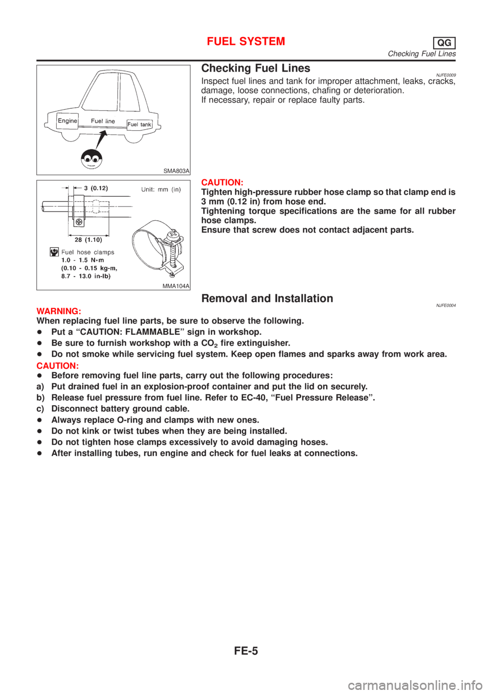
Checking Fuel LinesNJFE0009Inspect fuel lines and tank for improper attachment, leaks, cracks,
damage, loose connections, chafing or deterioration.
If necessary, repair or replace faulty parts.
MMA104A
CAUTION:
Tighten high-pressure rubber hose clamp so that clamp end is
3 mm (0.12 in) from hose end.
Tightening torque specifications are the same for all rubber
hose clamps.
Ensure that screw does not contact adjacent parts.
Removal and InstallationNJFE0004WARNING:
When replacing fuel line parts, be sure to observe the following.
+Put a ªCAUTION: FLAMMABLEº sign in workshop.
+Be sure to furnish workshop with a CO
2fire extinguisher.
+Do not smoke while servicing fuel system. Keep open flames and sparks away from work area.
CAUTION:
+Before removing fuel line parts, carry out the following procedures:
a) Put drained fuel in an explosion-proof container and put the lid on securely.
b) Release fuel pressure from fuel line. Refer to EC-40, ªFuel Pressure Releaseº.
c) Disconnect battery ground cable.
+Always replace O-ring and clamps with new ones.
+Do not kink or twist tubes when they are being installed.
+Do not tighten hose clamps excessively to avoid damaging hoses.
+After installing tubes, run engine and check for fuel leaks at connections.
FUEL SYSTEMQG
Checking Fuel Lines
FE-5
Page 2311 of 2898
SFE649A
JFE613A
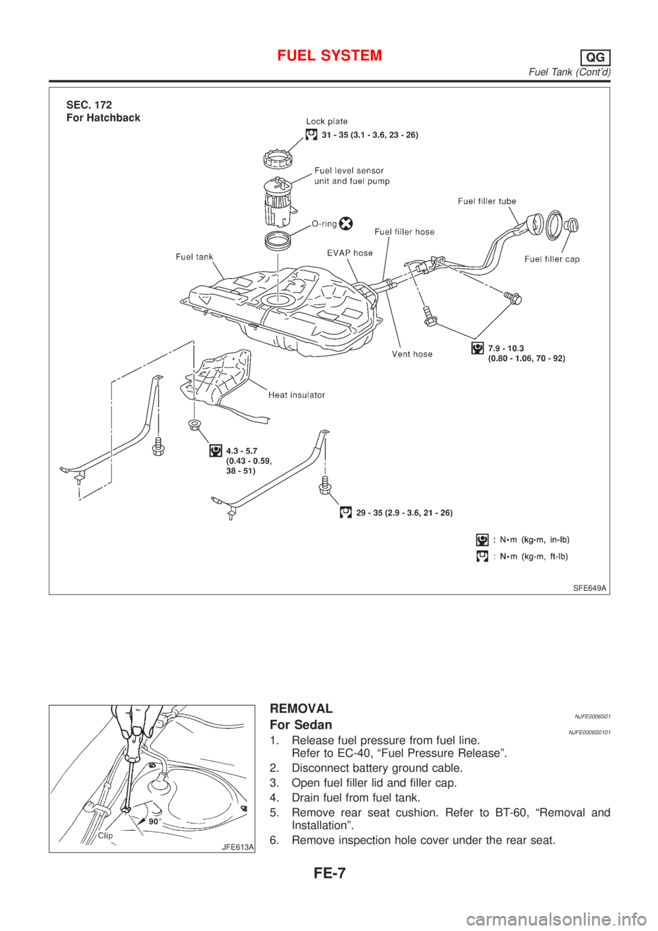
REMOVALNJFE0006S01For SedanNJFE0006S01011. Release fuel pressure from fuel line.
Refer to EC-40, ªFuel Pressure Releaseº.
2. Disconnect battery ground cable.
3. Open fuel filler lid and filler cap.
4. Drain fuel from fuel tank.
5. Remove rear seat cushion. Refer to BT-60, ªRemoval and
Installationº.
6. Remove inspection hole cover under the rear seat.
FUEL SYSTEMQG
Fuel Tank (Cont'd)
FE-7
Page 2312 of 2898
JFE608A
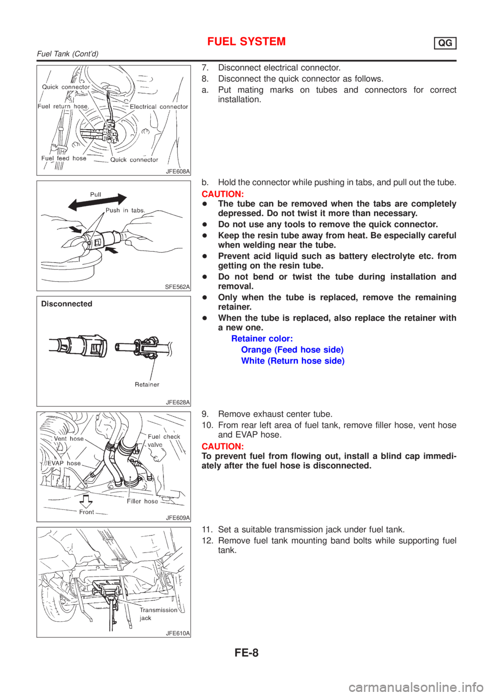
7. Disconnect electrical connector.
8. Disconnect the quick connector as follows.
a. Put mating marks on tubes and connectors for correct
installation.
SFE562A
JFE628A
b. Hold the connector while pushing in tabs, and pull out the tube.
CAUTION:
+The tube can be removed when the tabs are completely
depressed. Do not twist it more than necessary.
+Do not use any tools to remove the quick connector.
+Keep the resin tube away from heat. Be especially careful
when welding near the tube.
+Prevent acid liquid such as battery electrolyte etc. from
getting on the resin tube.
+Do not bend or twist the tube during installation and
removal.
+Only when the tube is replaced, remove the remaining
retainer.
+When the tube is replaced, also replace the retainer with
a new one.
Retainer color:
Orange (Feed hose side)
White (Return hose side)
JFE609A
9. Remove exhaust center tube.
10. From rear left area of fuel tank, remove filler hose, vent hose
and EVAP hose.
CAUTION:
To prevent fuel from flowing out, install a blind cap immedi-
ately after the fuel hose is disconnected.
JFE610A
11. Set a suitable transmission jack under fuel tank.
12. Remove fuel tank mounting band bolts while supporting fuel
tank.
FUEL SYSTEMQG
Fuel Tank (Cont'd)
FE-8