2001 NISSAN ALMERA fuel tank removal
[x] Cancel search: fuel tank removalPage 2332 of 2898

SFE642A
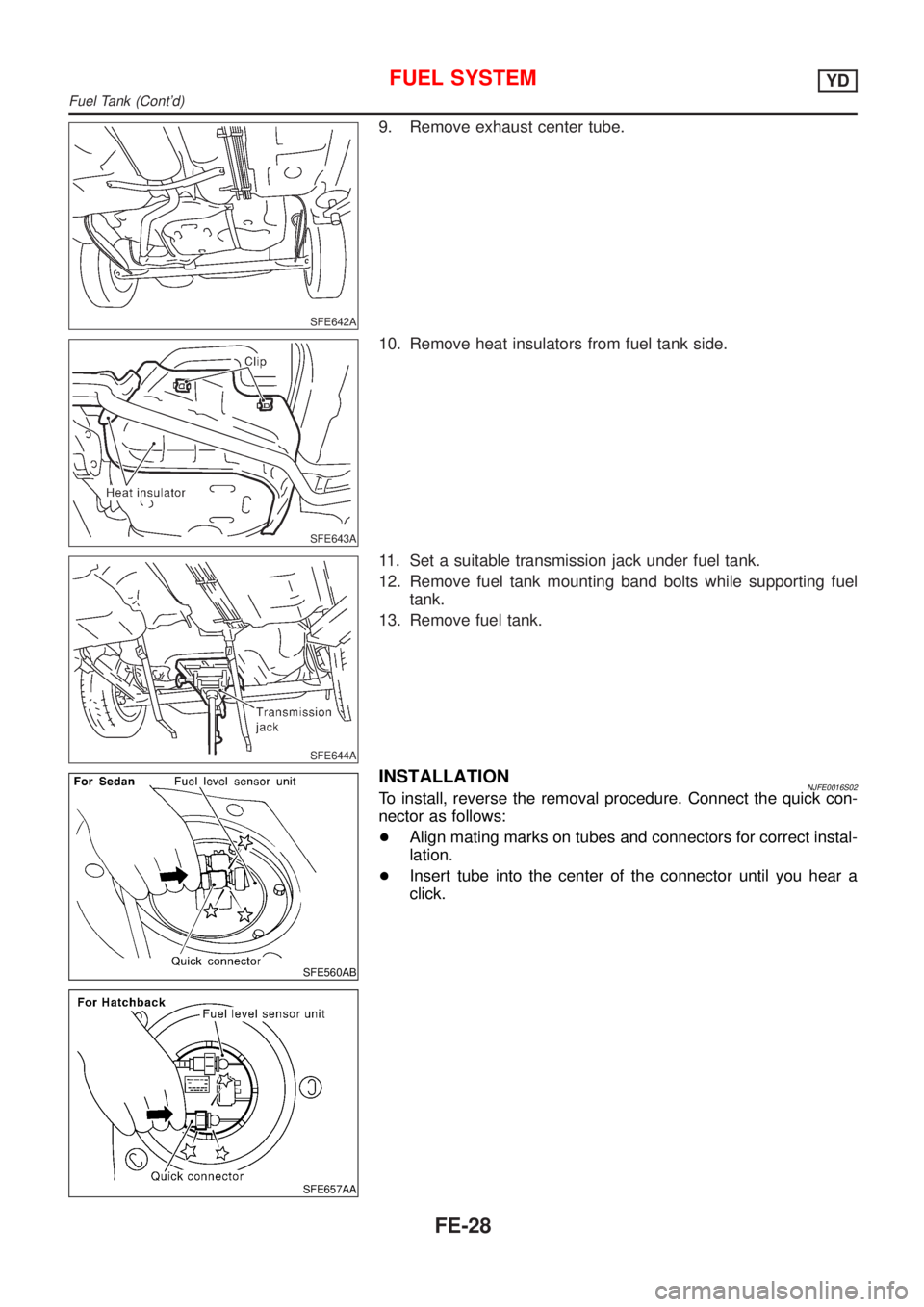
9. Remove exhaust center tube.
SFE643A
10. Remove heat insulators from fuel tank side.
SFE644A
11. Set a suitable transmission jack under fuel tank.
12. Remove fuel tank mounting band bolts while supporting fuel
tank.
13. Remove fuel tank.
SFE560AB
SFE657AA
INSTALLATIONNJFE0016S02To install, reverse the removal procedure. Connect the quick con-
nector as follows:
+Align mating marks on tubes and connectors for correct instal-
lation.
+Insert tube into the center of the connector until you hear a
click.
FUEL SYSTEMYD
Fuel Tank (Cont'd)
FE-28
Page 2334 of 2898

JFE613A
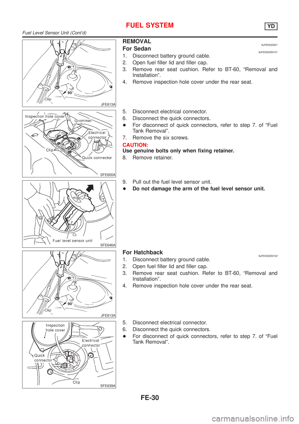
REMOVALNJFE0032S01For SedanNJFE0032S01011. Disconnect battery ground cable.
2. Open fuel filler lid and filler cap.
3. Remove rear seat cushion. Refer to BT-60, ªRemoval and
Installationº.
4. Remove inspection hole cover under the rear seat.
SFE600A
5. Disconnect electrical connector.
6. Disconnect the quick connectors.
+For disconnect of quick connectors, refer to step 7. of ªFuel
Tank Removalº.
7. Remove the six screws.
CAUTION:
Use genuine bolts only when fixing retainer.
8. Remove retainer.
SFE646A
9. Pull out the fuel level sensor unit.
+Do not damage the arm of the fuel level sensor unit.
JFE613A
For HatchbackNJFE0032S01021. Disconnect battery ground cable.
2. Open fuel filler lid and filler cap.
3. Remove rear seat cushion. Refer to BT-60, ªRemoval and
Installationº.
4. Remove inspection hole cover under the rear seat.
SFE639A
5. Disconnect electrical connector.
6. Disconnect the quick connectors.
+For disconnect of quick connectors, refer to step 7. of ªFuel
Tank Removalº.
FUEL SYSTEMYD
Fuel Level Sensor Unit (Cont'd)
FE-30
Page 2352 of 2898

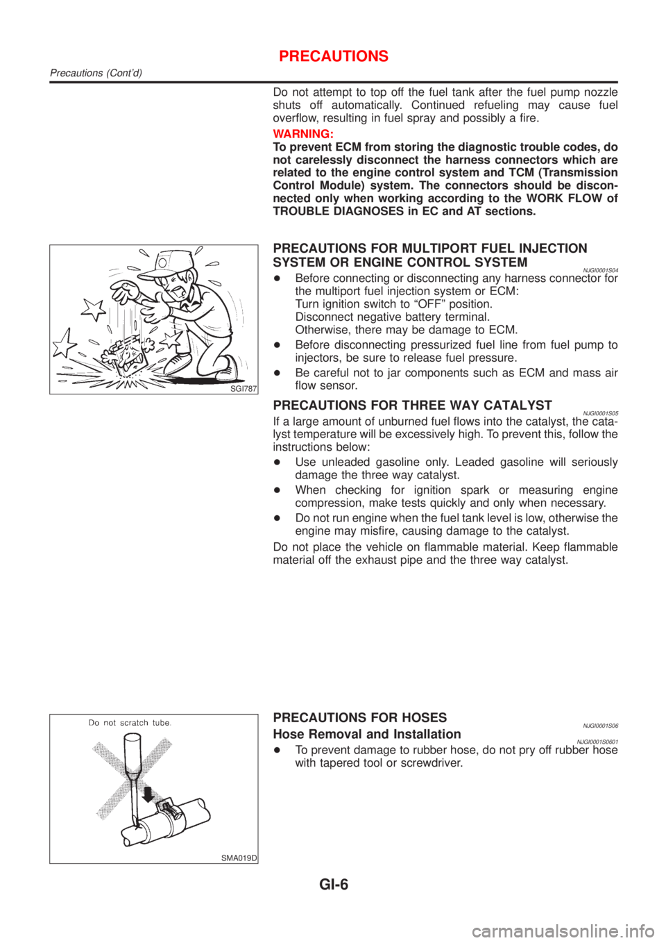
Do not attempt to top off the fuel tank after the fuel pump nozzle
shuts off automatically. Continued refueling may cause fuel
overflow, resulting in fuel spray and possibly a fire.
WARNING:
To prevent ECM from storing the diagnostic trouble codes, do
not carelessly disconnect the harness connectors which are
related to the engine control system and TCM (Transmission
Control Module) system. The connectors should be discon-
nected only when working according to the WORK FLOW of
TROUBLE DIAGNOSES in EC and AT sections.
SGI787
PRECAUTIONS FOR MULTIPORT FUEL INJECTION
SYSTEM OR ENGINE CONTROL SYSTEM
NJGI0001S04+Before connecting or disconnecting any harness connector for
the multiport fuel injection system or ECM:
Turn ignition switch to ªOFFº position.
Disconnect negative battery terminal.
Otherwise, there may be damage to ECM.
+Before disconnecting pressurized fuel line from fuel pump to
injectors, be sure to release fuel pressure.
+Be careful not to jar components such as ECM and mass air
flow sensor.
PRECAUTIONS FOR THREE WAY CATALYSTNJGI0001S05If a large amount of unburned fuel flows into the catalyst, the cata-
lyst temperature will be excessively high. To prevent this, follow the
instructions below:
+Use unleaded gasoline only. Leaded gasoline will seriously
damage the three way catalyst.
+When checking for ignition spark or measuring engine
compression, make tests quickly and only when necessary.
+Do not run engine when the fuel tank level is low, otherwise the
engine may misfire, causing damage to the catalyst.
Do not place the vehicle on flammable material. Keep flammable
material off the exhaust pipe and the three way catalyst.
SMA019D
PRECAUTIONS FOR HOSESNJGI0001S06Hose Removal and InstallationNJGI0001S0601+To prevent damage to rubber hose, do not pry off rubber hose
with tapered tool or screwdriver.
PRECAUTIONS
Precautions (Cont'd)
GI-6
Page 2502 of 2898

Electronic fuel injection pump ........ EC-618, 716,
723, 757, 764, 771, 778, 785, 803
Engine compartment ................................. BT-78
Engine control circuit diagram .......... EC-25, 606
Engine control component parts
location .......................................... EC-21, 603
Engine control module (ECM) ....... EC-391, 659,
714, 792, 794, 799, 801
Engine control system diagram and
chart .............................................. EC-29, 608
Engine coolant temperature sensor
(ECTS) ........................................ EC-201, 680
Engine fail-safe system ........................... EC-154
Engine oil precautions .................................. GI-7
Engine outer component parts ................. EM-11
Engine removal ................................ EM-51, 137
Engine room - See Engine
compartment .......................................... BT-78
Engine serial number ................................. GI-41
Evaporative emission (EVAP)
system ................................................... EC-36
Exhaust gas recirculation (EGR)
valve .................................... EC-343, 425, 491
Exhaust system ................................... FE-15, 32
Exterior ...................................................... BT-47
F
F/PUMP - Wiring diagram ....................... EC-563
FR02 - Wiring diagram ... EC-219, 239, 247, 451
FR02/H - Wiring diagram ................ EC-254, 458
FUEL - Wiring diagram ................... EC-299, 307
Fan switch ................................................. HA-54
Final drive (FF A/T) .................................. AT-442
Final drive (FF M/T) .............. MT-44, 77, 93, 107
Finisher, interior - See Trim ....................... BT-31
Finisher, trunk lid ....................................... BT-45
Floor trim ................................................... BT-31
Fluid temperature sensor (A/T) ................ AT-194
Fluids ........................................................ MA-16
Flywheel (clutch) ....................................... CL-22
Flywheel runout ................................ EM-62, 154
Fog lamp, front, removal and
installation ................................................ BT-7
Fog lamp, front .......................................... EL-89
Fork rod (M/T) .............................. MT-32, 56, 94
Forward clutch ......................................... AT-412
Freeze frame data .............................. EC-61, 72
Front axle .................................................... AX-2
Front bumper ............................................... BT-7
Front combination lamp removal and
installation ................................................ BT-7
Front disc brake ........................................ BR-27
Front door .................................................. BT-16
Front fog lamp removal and
installation ................................................ BT-7
Front fog lamp ........................................... EL-89
Front heated oxygen sensor (HO2S)
heater .......................................... EC-252, 457Front heated oxygen sensor (HO2S) ..... EC-216,
224, 230, 236, 245, 450
Front seat belt ............................................. RS-5
Front seat .................................................. BT-56
Front suspension ........................................ SU-2
Front washer ............................................ EL-215
Front wiper ............................................... EL-215
Fuel cut control (at no load & high
engine speed) ............................... EC-36, 612
Fuel gauge ............................................... EL-144
Fuel injection system .............. EC-297, 305, 610
Fuel injector ............................................ EC-541
Fuel precautions ........................................... GI-8
Fuel pressure check ................................. EC-40
Fuel pressure regulator ............................. EC-41
Fuel pressure release ............................... EC-40
Fuel pump relay ...................................... EC-561
Fuel pump ............................................... EC-561
Fuel system ........................................... FE-5, 20
Fuel tank vacuum relief valve ................... EC-37
Fuse block ............................................... EL-577
Fuse ........................................................... EL-38
Fusible link ................................................. EL-38
G
GLOW - Wiring diagram ......................... EC-806
Garage jack and safety stand .................... GI-45
Gauges .................................................... EL-144
Gear components (M/T) ............... MT-31, 55, 93
Generator - See Alternator ....................... SC-31
Generic scan tool (GST) ........................... EC-94
Glass .......................................................... BT-17
Glow plug ................................................ EC-806
Glow relay ............................................... EC-806
Grease ...................................................... MA-16
Ground distribution .................................... EL-39
H
H/LAMP - Wiring diagram ................... EL-60, 61
HEATER - Wiring diagram ........................ HA-24
HFC134a (R134a) system
precaution ................................................ HA-2
HFC134a (R134a) system service
procedure .............................................. HA-78
HFC134a (R134a) system service
tools ....................................................... HA-11
HFC134a system service equipment
precaution ................................................ HA-6
HORN - Wiring diagram .................. EL-234, 235
HSEAT - Wiring diagram ................. EL-288, 290
Harness connector ...................................... EL-6
Harness layout ......................................... EL-522
Hazard warning lamp ................................ EL-96
Headlamp removal and installation ............. BT-7
Headlamp washer .................................... EL-231
Headlamp .................................................. EL-60
ALPHABETICAL INDEX
IDX-4