Page 353 of 2898
SAT992C
Control Valve Assembly and AccumulatorsNJAT0110REMOVALNJAT0110S011. Drain ATF from transaxle.
2. Remove oil pan and gasket.
SAT064K
3. Disconnect A/T solenoid valve harness connector.
AAT265A
4. Remove stopper ring from A/T solenoid harness terminal body.
5. Remove A/T solenoid harness by pushing terminal body into
transmission case.
AAT260A
6. Remove control valve assembly by removing fixing bolts.
Bolt length, number and location:
Bolt symbol A B C
Bolt length ª!º
40.0 mm
(1.575 in)33.0 mm
(1.299 in)43.5 mm
(1.713 in)
Number of bolts 5 6 2
+Be careful not to drop manual valve and servo release
accumulator return springs.
7. Disassemble and inspect control valve assembly if necessary.
Refer to AT-366.
ON-VEHICLE SERVICE
Control Valve Assembly and Accumulators
AT-351
Page 354 of 2898

SAT935J
8. Remove servo release and N-D accumulators by applying
compressed air if necessary.
+Hold each piston with a rag.
SAT497H
INSTALLATIONNJAT0110S02+Tighten fixing bolts to specification.
:7-9N´m(0.7 - 0.9 kg-m, 61 - 78 in-lb)
+Set manual shaft in Neutral position, then align manual
plate with groove in manual valve.
+After installing control valve assembly to transmission
case, make sure that selector lever can be moved to all
positions.
AAT980
Control Cable AdjustmentNJAT0111Move selector lever from the ªPº position to the ª1º position. You
should be able to feel the detents in each position. If the detents
cannot be felt or if the pointer indicating the position is improperly
aligned, the control cable needs adjustment.
1. Place selector lever in ªPº position.
2. Loosen control cable lock nut and place manual shaft in ªPº
position.
3. Pull control cable, by specified force, in the direction of the
arrow shown in the illustration.
Specified force: 6.9 N (0.7 kg, 1.5 lb)
4. Return control cable in the opposite direction of the arrow for
1.0 mm (0.039 in).
5. Tighten control cable lock nut.
6. Move selector lever from ªPº to ª1º position again. Make sure
that selector lever moves smoothly.
7. Apply grease to contacting areas of selector lever and control
cable. Install any part removed.
SAT479J
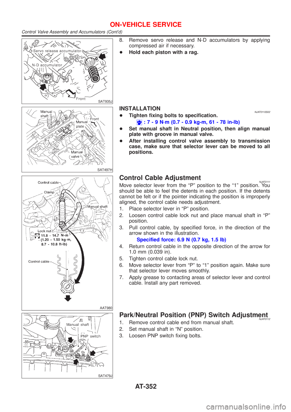
Park/Neutral Position (PNP) Switch AdjustmentNJAT01121. Remove control cable end from manual shaft.
2. Set manual shaft in ªNº position.
3. Loosen PNP switch fixing bolts.
ON-VEHICLE SERVICE
Control Valve Assembly and Accumulators (Cont'd)
AT-352
Page 370 of 2898
AAT262A
b. Remove stopper ring from terminal body.
c. Push terminal body into transmission case and draw out sole-
noid harness.
SAT017D
10. Remove manual valve from control valve assembly as a pre-
caution.
SAT877J
11. Remove return spring from servo release accumulator piston.
SAT019DA
12. Remove servo release accumulator piston with compressed
air.
13. Remove O-rings from servo release accumulator piston.
SAT020D
14. Remove N-D accumulator piston and return spring with com-
pressed air.
15. Remove O-rings from N-D accumulator piston.
DISASSEMBLY
AT-368
Page 378 of 2898
SAT272E
38. Remove forward clutch assembly from transmission case.
AAT215A
39. Remove thrust washer from transmission case.
SAT702D
3AX00, 3AX01, 3AX19, 3AX63 and 3AX64 models
40. Remove side cover.
+Do not reuse side cover bolts.
SAT703D
41. Remove output shaft, output gear and reduction gear accord-
ing to the following procedures.
a. Set manual lever to ªPº position to fix idler gear and output
gear.
b. Unlock both idler gear and output gear lock nuts using a pin
punch.
SAT704D
c. Remove idler gear and output gear lock nuts.
+Do not reuse idler gear and output gear lock nuts.
DISASSEMBLY
AT-376
Page 383 of 2898
Manual Shaft
COMPONENTSNJAT0121
SAT481J
SAT313G
REMOVALNJAT01221. Remove detent spring from transmission case.
SAT076D
2. Drive out manual plate retaining pin.
SAT077D
3. Drive and pull out parking rod plate retaining pin.
4. Remove parking rod plate from manual shaft.
5. Draw out parking rod from transmission case.
REPAIR FOR COMPONENT PARTS
Manual Shaft
AT-381
Page 384 of 2898
SAT049F
6. Pull out manual shaft retaining pin.
7. Remove manual shaft and manual plate from transmission
case.
SAT080D
8. Remove manual shaft oil seal.
INSPECTIONNJAT0123+Check component parts for wear or damage. Replace if nec-
essary.
SAT081D
INSTALLATIONNJAT01241. Install manual shaft oil seal.
+Apply ATF to outer surface of oil seal.
SAT610H
2. Install manual shaft and manual plate.
REPAIR FOR COMPONENT PARTS
Manual Shaft (Cont'd)
AT-382
Page 385 of 2898
SAT074E
3. Align groove of manual shaft and hole of transmission case.
4. Install manual shaft retaining pin.
SAT078D
5. Install parking rod to parking rod plate.
6. Set parking rod assembly onto manual shaft.
SAT087D
7. Drive in manual plate retaining pin and parking rod plate retain-
ing pin.
SAT313G
8. Install detent spring.
REPAIR FOR COMPONENT PARTS
Manual Shaft (Cont'd)
AT-383
Page 468 of 2898
SAT407DA
b. Install O-rings on accumulator piston.
+Apply ATF to O-rings.
Accumulator piston O-rings:
Refer to SDS, AT-484.
SAT878J
c. Install accumulator pistons and return springs on transmission
case.
+Apply ATF to inner surface of transmission case.
Return springs:
Refer to SDS, AT-484.
SAT021D
SAT022D
6. Install lip seals for band servo oil holes on transmission case.
+Apply petroleum jelly to lip seals.
SAT017D
7. Install control valve assembly.
a. Insert manual valve into control valve assembly.
+Apply ATF to manual valve.
ASSEMBLY
Assembly (4) (Cont'd)
AT-466