Page 1660 of 2898

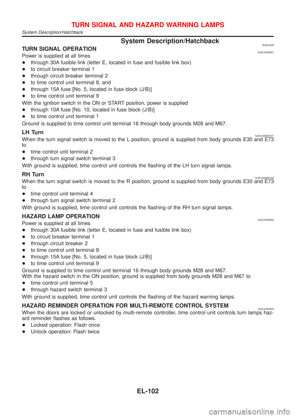
System Description/HatchbackNJEL0430TURN SIGNAL OPERATIONNJEL0430S01Power is supplied at all times
+through 30A fusible link (letter E, located in fuse and fusible link box)
+to circuit breaker terminal 1
+through circuit breaker terminal 2
+to time control unit terminal 8, and
+through 15A fuse [No. 5, located in fuse block (J/B)]
+to time control unit terminal 9
With the ignition switch in the ON or START position, power is supplied
+through 10A fuse [No. 10, located in fuse block (J/B)]
+to time control unit terminal 1
Ground is supplied to time control unit terminal 16 through body grounds M28 and M67.
LH TurnNJEL0430S0101When the turn signal switch is moved to the L position, ground is supplied from body grounds E30 and E73
to
+time control unit terminal 2
+through turn signal switch terminal 3
With ground is supplied, time control unit controls the flashing of the LH turn signal lamps.
RH TurnNJEL0430S0102When the turn signal switch is moved to the R position, ground is supplied from body grounds E30 and E73
to
+time control unit terminal 4
+through turn signal switch terminal 2
With ground is supplied, time control unit controls the flashing of the RH turn signal lamps.
HAZARD LAMP OPERATIONNJEL0430S02Power is supplied at all times
+through 30A fusible link (letter E, located in fuse and fusible link box)
+to circuit breaker terminal 1
+through circuit breaker 2
+to time control unit terminal 8
+through 15A fuse [No. 5, located in fuse block (J/B)]
+to time control unit terminal 9
Ground is supplied to time control unit terminal 16 through body grounds M28 and M67.
With the hazard switch in the ON position, ground is supplied from body grounds M28 and M67 to
+time control unit terminal 5
+through hazard switch terminal 3
With ground is supplied, time control unit controls the flashing of the hazard warning lamps.
HAZARD REMINDER OPERATION FOR MULTI-REMOTE CONTROL SYSTEMNJEL0430S04When the doors are locked or unlocked by multi-remote controller, time control unit controls turn lamps haz-
ard reminder flashes as follows.
+Locked operation: Flash once
+Unlock operation: Flash twice
TURN SIGNAL AND HAZARD WARNING LAMPS
System Description/Hatchback
EL-102
Page 1673 of 2898
![NISSAN ALMERA 2001 Service Manual System Description/Sedan With Interior Room
Lamp Timer
=NJEL0366POWER SUPPLY AND GROUNDNJEL0366S01Power is supplied at all times:
+through 10A fuse [No. 12, located in the fuse block (J/B)]
+to key sw NISSAN ALMERA 2001 Service Manual System Description/Sedan With Interior Room
Lamp Timer
=NJEL0366POWER SUPPLY AND GROUNDNJEL0366S01Power is supplied at all times:
+through 10A fuse [No. 12, located in the fuse block (J/B)]
+to key sw](/manual-img/5/57348/w960_57348-1672.png)
System Description/Sedan With Interior Room
Lamp Timer
=NJEL0366POWER SUPPLY AND GROUNDNJEL0366S01Power is supplied at all times:
+through 10A fuse [No. 12, located in the fuse block (J/B)]
+to key switch terminal 1 and
+to time control unit terminal 1
+through 10A fuse [No. 13, located in the fuse block (J/B)]
+to interior room lamp terminal 1.
When the key is removed from ignition key cylinder, power is interrupted:
+through key switch terminal 2
+to time control unit terminal 18.
With the ignition key switch in the ON or START position, power is supplied:
+through 10A fuse [No. 10, located in the fuse block (J/B)]
+to time control unit terminal 17.
Ground is supplied:
+through body grounds terminals M28 and M67
+to time control unit terminal 16
When the driver side door is opened, ground is supplied:
+through body grounds B9, B21 and B308
+to door switch driver side terminal 3
+from door switch driver side terminal 2
+to time control unit terminal 30.
When any door is opened, ground is supplied:
+through case ground of each door switch
+to each door switch terminal 1
+to time control unit terminal 31.
When the driver side door is unlocked, the time control unit receives a ground signal:
+through body grounds terminals M28 and M67
+to door unlock sensor terminal 2
+from door unlock sensor terminal 5
+to time control unit terminal 28.
When a signal, or combination of signals is received by the time control unit, ground is supplied:
+through time control unit terminal 26
+to interior room lamp terminal 2.
With power and ground supplied, the interior room lamp illuminates.
SWITCH OPERATIONNJEL0366S02When interior room lamp switch is ON, ground is supplied:
+through case grounds of interior room lamp
+to interior room lamp.
INTERIOR ROOM LAMP TIMER OPERATIONNJEL0366S03When interior room lamp switch is in the ªDOORº position, the time control unit keeps the interior room lamp
illuminated for about 30 seconds when:
+unlock signal is supplied from driver's door unlock sensor or multi-remote controller while all doors are
closed and key is out of ignition key cylinder
+key is removed from ignition key cylinder while all doors are closed
+driver's door is opened and then closed while key is out of the iginition key cylinder. (However, if the driv-
er's door is closed with the key inserted in the ignition key cylinder after the driver's door is opened with
the key removed, the timer is operated.)
The timer is canceled when:
+driver's door is locked,
INTERIOR ROOM LAMP
System Description/Sedan With Interior Room Lamp Timer
EL-115
Page 2134 of 2898

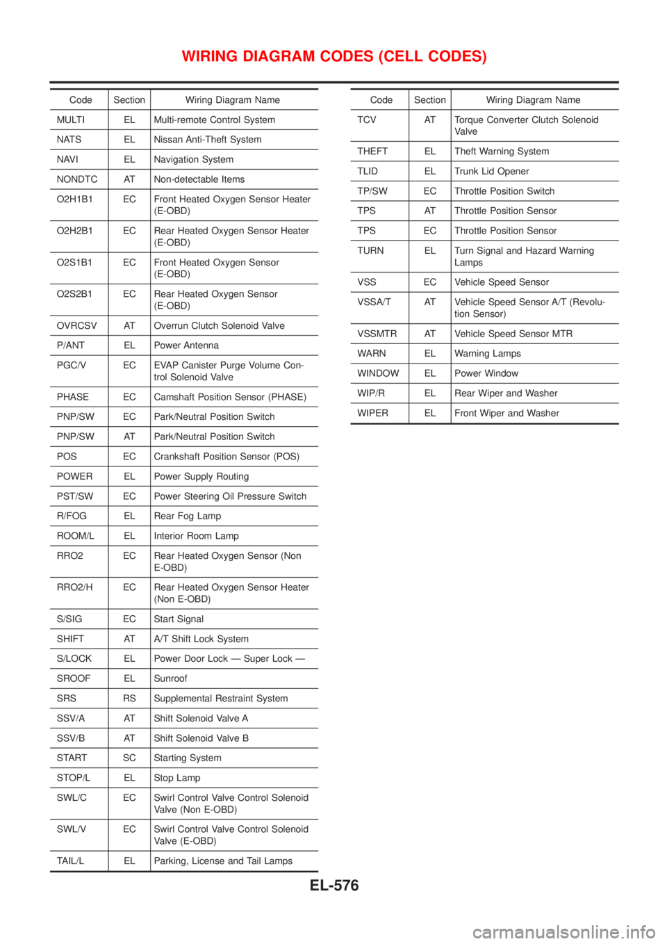
Code Section Wiring Diagram Name
MULTI EL Multi-remote Control System
NATS EL Nissan Anti-Theft System
NAVI EL Navigation System
NONDTC AT Non-detectable Items
O2H1B1 EC Front Heated Oxygen Sensor Heater
(E-OBD)
O2H2B1 EC Rear Heated Oxygen Sensor Heater
(E-OBD)
O2S1B1 EC Front Heated Oxygen Sensor
(E-OBD)
O2S2B1 EC Rear Heated Oxygen Sensor
(E-OBD)
OVRCSV AT Overrun Clutch Solenoid Valve
P/ANT EL Power Antenna
PGC/V EC EVAP Canister Purge Volume Con-
trol Solenoid Valve
PHASE EC Camshaft Position Sensor (PHASE)
PNP/SW EC Park/Neutral Position Switch
PNP/SW AT Park/Neutral Position Switch
POS EC Crankshaft Position Sensor (POS)
POWER EL Power Supply Routing
PST/SW EC Power Steering Oil Pressure Switch
R/FOG EL Rear Fog Lamp
ROOM/L EL Interior Room Lamp
RRO2 EC Rear Heated Oxygen Sensor (Non
E-OBD)
RRO2/H EC Rear Heated Oxygen Sensor Heater
(Non E-OBD)
S/SIG EC Start Signal
SHIFT AT A/T Shift Lock System
S/LOCK EL Power Door Lock Ð Super Lock Ð
SROOF EL Sunroof
SRS RS Supplemental Restraint System
SSV/A AT Shift Solenoid Valve A
SSV/B AT Shift Solenoid Valve B
START SC Starting System
STOP/L EL Stop Lamp
SWL/C EC Swirl Control Valve Control Solenoid
Valve (Non E-OBD)
SWL/V EC Swirl Control Valve Control Solenoid
Valve (E-OBD)
TAIL/L EL Parking, License and Tail LampsCode Section Wiring Diagram Name
TCV AT Torque Converter Clutch Solenoid
Valve
THEFT EL Theft Warning System
TLID EL Trunk Lid Opener
TP/SW EC Throttle Position Switch
TPS AT Throttle Position Sensor
TPS EC Throttle Position Sensor
TURN EL Turn Signal and Hazard Warning
Lamps
VSS EC Vehicle Speed Sensor
VSSA/T AT Vehicle Speed Sensor A/T (Revolu-
tion Sensor)
VSSMTR AT Vehicle Speed Sensor MTR
WARN EL Warning Lamps
WINDOW EL Power Window
WIP/R EL Rear Wiper and Washer
WIPER EL Front Wiper and Washer
WIRING DIAGRAM CODES (CELL CODES)
EL-576