2001 NISSAN ALMERA fuse box
[x] Cancel search: fuse boxPage 807 of 2898
SEF094Y
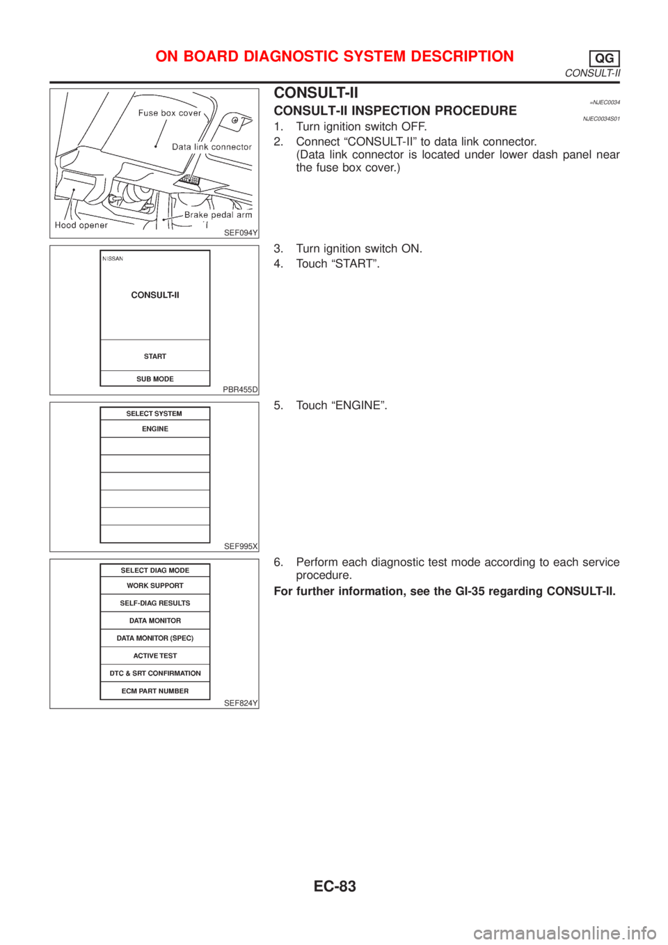
CONSULT-II=NJEC0034CONSULT-II INSPECTION PROCEDURENJEC0034S011. Turn ignition switch OFF.
2. Connect ªCONSULT-IIº to data link connector.
(Data link connector is located under lower dash panel near
the fuse box cover.)
PBR455D
3. Turn ignition switch ON.
4. Touch ªSTARTº.
SEF995X
5. Touch ªENGINEº.
SEF824Y
6. Perform each diagnostic test mode according to each service
procedure.
For further information, see the GI-35 regarding CONSULT-II.
ON BOARD DIAGNOSTIC SYSTEM DESCRIPTIONQG
CONSULT-II
EC-83
Page 818 of 2898
SEF139P
Generic Scan Tool (GST)=NJEC0035DESCRIPTIONNJEC0035S01Generic Scan Tool (OBDII scan tool) complying with ISO15031-4
has 9 different functions explained on the next page.
ISO9141 is used as the protocol.
The name ªGSTº or ªGeneric Scan Toolº is used in this service
manual.
SEF094Y
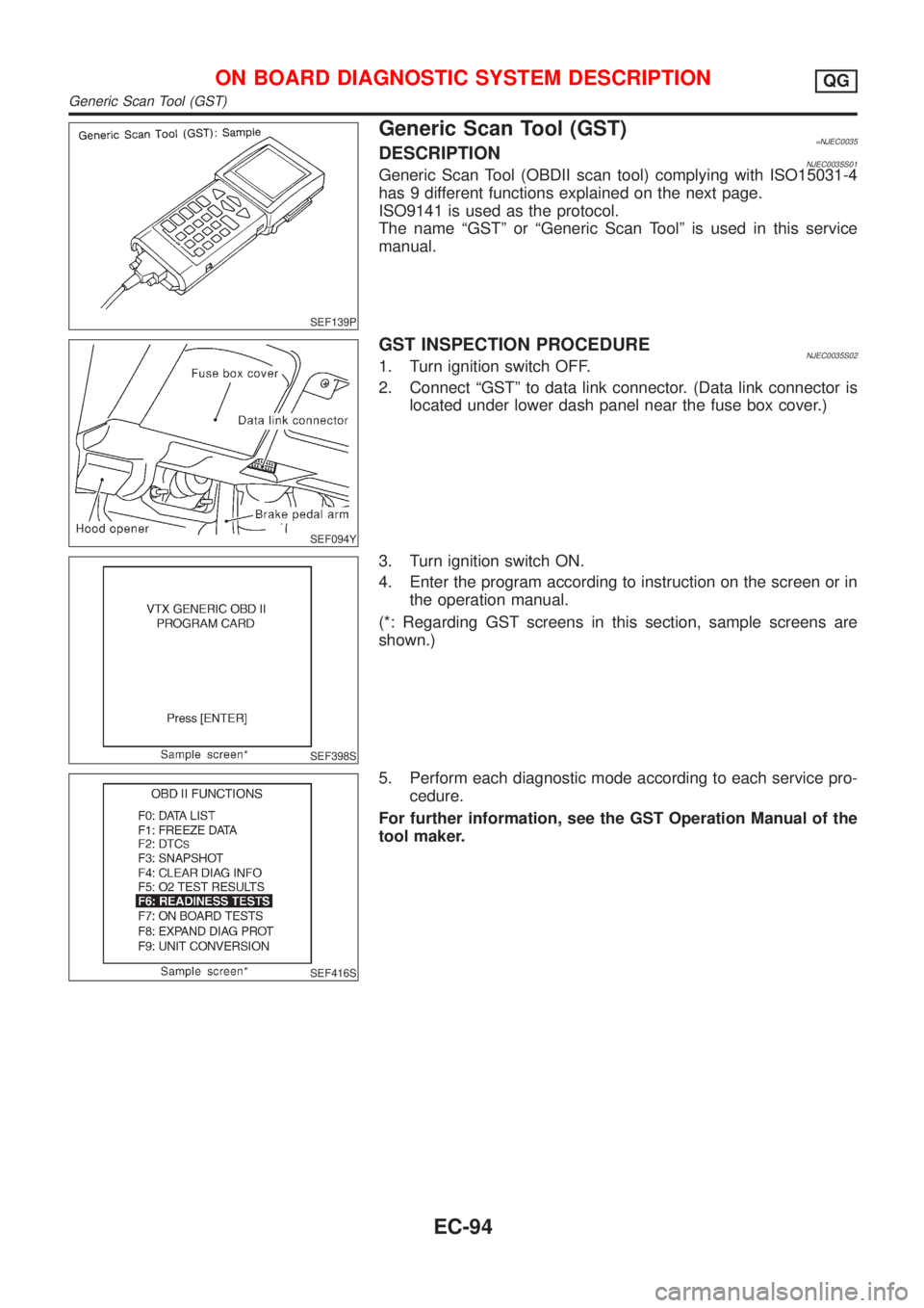
GST INSPECTION PROCEDURENJEC0035S021. Turn ignition switch OFF.
2. Connect ªGSTº to data link connector. (Data link connector is
located under lower dash panel near the fuse box cover.)
SEF398S
3. Turn ignition switch ON.
4. Enter the program according to instruction on the screen or in
the operation manual.
(*: Regarding GST screens in this section, sample screens are
shown.)
SEF416S
5. Perform each diagnostic mode according to each service pro-
cedure.
For further information, see the GST Operation Manual of the
tool maker.
ON BOARD DIAGNOSTIC SYSTEM DESCRIPTIONQG
Generic Scan Tool (GST)
EC-94
Page 909 of 2898

12 CHECK ECM POWER SUPPLY CIRCUIT-IV
1. Disconnect ECM relay. (For ECM relay location, refer to ªEngine Control Compartment Parts Locationº.)
2. Check voltage between ECM relay terminal 3 or 5 (only ECM relay in relay box) and ground with CONSULT-II or tester.
YEC048A
OK or NG
OK©GO TO 14.
NG©GO TO 13.
13 DETECT MALFUNCTIONING PART
Check the following.
+Harness connectors E75, F36 (If so equipped)
+Harness for open or short between ECM relay and 10A fuse
©Repair open circuit or short to ground or short to power in harness or connectors.
14 CHECK HARNESS CONTINUITY BETWEEN ECM RELAY AND ECM FOR OPEN AND SHORT
1. Check harness continuity between ECM terminals 110, 112 and ECM relay terminal 5 or 3 (only ECM relay in relay
box).
Refer to WIRING DIAGRAM.
Continuity should exist.
2. Also check harness for short to ground and short to power.
OK or NG
OK©GO TO 16.
NG©GO TO 15.
15 DETECT MALFUNCTIONING PART
Check the following.
+Joint connector-4 (If so equipped)
+Joint connector-6 (If so equipped)
+Harness connector E75, F36 (If so equipped)
+Harness for open or short between ECM and ECM relay
©Repair open circuit or short to ground or short to power in harness or connectors.
TROUBLE DIAGNOSIS FOR POWER SUPPLYQG
Main Power Supply and Ground Circuit (Cont'd)
EC-185
Page 1621 of 2898
Trouble DiagnosesNJEL0202
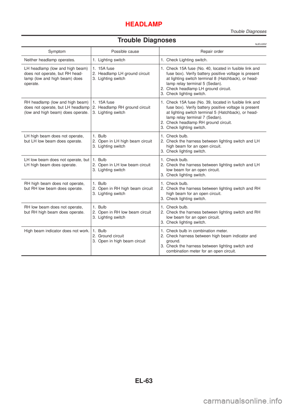
Symptom Possible cause Repair order
Neither headlamp operates. 1. Lighting switch 1. Check Lighting switch.
LH headlamp (low and high beam)
does not operate, but RH head-
lamp (low and high beam) does
operate.1. 15A fuse
2. Headlamp LH ground circuit
3. Lighting switch1. Check 15A fuse (No. 40, located in fusible link and
fuse box). Verify battery positive voltage is present
at lighting switch terminal 8 (Hatchback), or head-
lamp relay terminal 5 (Sedan).
2. Check headlamp LH ground circuit.
3. Check lighting switch.
RH headlamp (low and high beam)
does not operate, but LH headlamp
(low and high beam) does operate.1. 15A fuse
2. Headlamp RH ground circuit
3. Lighting switch1. Check 15A fuse (No. 39, located in fusible link and
fuse box). Verify battery positive voltage is present
at lighting switch terminal 5 (Hatchback), or head-
lamp relay terminal 7 (Sedan).
2. Check headlamp RH ground circuit.
3. Check lighting switch.
LH high beam does not operate,
but LH low beam does operate.1. Bulb
2. Open in LH high beam circuit
3. Lighting switch1. Check bulb.
2. Check the harness between lighting switch and LH
high beam for an open circuit.
3. Check lighting switch.
LH low beam does not operate, but
LH high beam does operate.1. Bulb
2. Open in LH low beam circuit
3. Lighting switch1. Check bulb.
2. Check the harness between lighting switch and LH
low beam for an open circuit.
3. Check lighting switch.
RH high beam does not operate,
but RH low beam does operate.1. Bulb
2. Open in RH high beam circuit
3. Lighting switch1. Check bulb.
2. Check the harness between lighting switch and RH
high beam for an open circuit.
3. Check lighting switch.
RH low beam does not operate,
but RH high beam does operate.1. Bulb
2. Open in RH low beam circuit
3. Lighting switch1. Check bulb.
2. Check the harness between lighting switch and RH
low beam for an open circuit.
3. Check lighting switch.
High beam indicator does not work. 1. Bulb
2. Ground circuit
3. Open in high beam circuit1. Check bulb in combination meter.
2. Check harness between high beam indicator and
ground.
3. Check the harness between lighting switch and
combination meter for an open circuit.
HEADLAMP
Trouble Diagnoses
EL-63
Page 1625 of 2898
System DescriptionNJEL0351The headlamp system on vehicles for North Europe contains a daytime light unit. The unit activates the fol-
lowing whenever the engine is running with the lighting switch in the OFF position:
+Low beam headlamps
+Parking, license, tail and illumination lamps
Power is supplied at all times
+through 10A fuse (No. 38, located in the fusible link and fuse box)
+to daytime light unit terminal 1 and
+to lighting switch terminal 11.
Power is also supplied at all times
+through 15A fuse (No. 39, located in the fusible link and fuse box)
+to daytime light unit terminal 3 and
+to lighting switch terminal 5.
Power is also supplied at all times
+through 15A fuse (No. 40, located in the fusible link and fuse box)
+to daytime light unit terminal 2 and
+to lighting switch terminal 8.
With the ignition switch in the ON or START position, power is supplied
+through 10A fuse [No. 20, located in the fuse block (J/B)]
+to daytime light unit terminal 7.
With the ignition switch in the START position, power is supplied
+through 10A fuse [No. 21, located in the fuse block (J/B)]
+to daytime light unit terminal 6.
Ground is supplied to daytime light unit terminal 9 through body grounds E30 and E73.
HEADLAMP OPERATION (DAYTIME LIGHT CANCEL OPERATION)NJEL0351S01When the lighting switch is turned to the 1st or 2nd position, power is supplied
+through lighting switch terminal 12,
+to daytime light unit terminal 11.
Then daytime light will be canceled. And the lighting system operation will be the same as no daytime light
system.
DAYTIME LIGHT OPERATIONNJEL0351S02With the engine running and the lighting switch in the OFF position, power is supplied
+from alternator terminal 3
+to daytime light unit terminal 8,
+through daytime light unit terminal 5
+to terminal 3 of headlamp LH,
+through daytime light unit terminal 4
+to terminal 3 of headlamp RH and
+through daytime light unit terminal 10
+to tail lamp and illumination.
Ground is supplied to terminal 2 of each headlamp through body grounds E30 and E73.
HEADLAMP Ð DAYTIME LIGHT SYSTEM Ð
System Description
EL-67
Page 1660 of 2898
System Description/HatchbackNJEL0430TURN SIGNAL OPERATIONNJEL0430S01Power is supplied at all times
+through 30A fusible link (letter E, located in fuse and fusible link box)
+to circuit breaker terminal 1
+through circuit breaker terminal 2
+to time control unit terminal 8, and
+through 15A fuse [No. 5, located in fuse block (J/B)]
+to time control unit terminal 9
With the ignition switch in the ON or START position, power is supplied
+through 10A fuse [No. 10, located in fuse block (J/B)]
+to time control unit terminal 1
Ground is supplied to time control unit terminal 16 through body grounds M28 and M67.
LH TurnNJEL0430S0101When the turn signal switch is moved to the L position, ground is supplied from body grounds E30 and E73
to
+time control unit terminal 2
+through turn signal switch terminal 3
With ground is supplied, time control unit controls the flashing of the LH turn signal lamps.
RH TurnNJEL0430S0102When the turn signal switch is moved to the R position, ground is supplied from body grounds E30 and E73
to
+time control unit terminal 4
+through turn signal switch terminal 2
With ground is supplied, time control unit controls the flashing of the RH turn signal lamps.
HAZARD LAMP OPERATIONNJEL0430S02Power is supplied at all times
+through 30A fusible link (letter E, located in fuse and fusible link box)
+to circuit breaker terminal 1
+through circuit breaker 2
+to time control unit terminal 8
+through 15A fuse [No. 5, located in fuse block (J/B)]
+to time control unit terminal 9
Ground is supplied to time control unit terminal 16 through body grounds M28 and M67.
With the hazard switch in the ON position, ground is supplied from body grounds M28 and M67 to
+time control unit terminal 5
+through hazard switch terminal 3
With ground is supplied, time control unit controls the flashing of the hazard warning lamps.
HAZARD REMINDER OPERATION FOR MULTI-REMOTE CONTROL SYSTEMNJEL0430S04When the doors are locked or unlocked by multi-remote controller, time control unit controls turn lamps haz-
ard reminder flashes as follows.
+Locked operation: Flash once
+Unlock operation: Flash twice
TURN SIGNAL AND HAZARD WARNING LAMPS
System Description/Hatchback
EL-102
Page 1756 of 2898
System Description/Sedan=NJEL0372The warning chime is controlled by the time control unit.
The warning chime is located in the time control unit.
Power is supplied at all times
+through 10A fuse [No. 12, located in the fuse block (J/B)]
+to key switch terminal 1,
+to time control unit terminal 1,
+through 10A fuse (No. 38, located in the fuse and fusible link box)
+to lighting switch terminal 11, and
+to daytime light unit terminal 1 (with daytime light system)
With the ignition switch in the ON or START position, power is supplied
+through 10A fuse [No. 10, located in the fuse block (J/B)]
+to time control unit terminal 17.
Ground is supplied to time control unit terminal 16 through body grounds M28 and M67.
When a signal, or combination of signals, is received by the time control unit, the warning chime will sound.
IGNITION KEY WARNING CHIMENJEL0372S01With the key in the ignition switch in the OFF position, the driver's door open and driver's door locked, the
warning chime will sound. Power is supplied
+from key switch terminal 2
+to time control unit terminal 18.
Ground is supplied
+from body grounds B9, B21 and B308
+to time control unit terminal 30, and
Ground is interrupted,
+from body grounds M28, M67 and B308
+to time control unit terminal 28
LIGHT WARNING CHIMENJEL0372S02With ignition switch OFF, driver's door open, and lighting switch in 1ST or 2ND position, warning chime will
sound. Power is supplied.
+from lighting switch terminal 12 or daytime light control unit terminal 10 (with daytime light system) to time
control unit terminal 19
Ground is supplied
+from door switch driver side terminal 2
+to time control unit terminal 30.
Door switch driver side terminal 3 is grounded through body grounds B9, B21 and B308.
WARNING CHIME
System Description/Sedan
EL-198
Page 1759 of 2898
DIAGNOSTIC PROCEDURE 1 (LIGHTING SWITCH
INPUT SIGNAL CHECK)
=NJEL0374S03
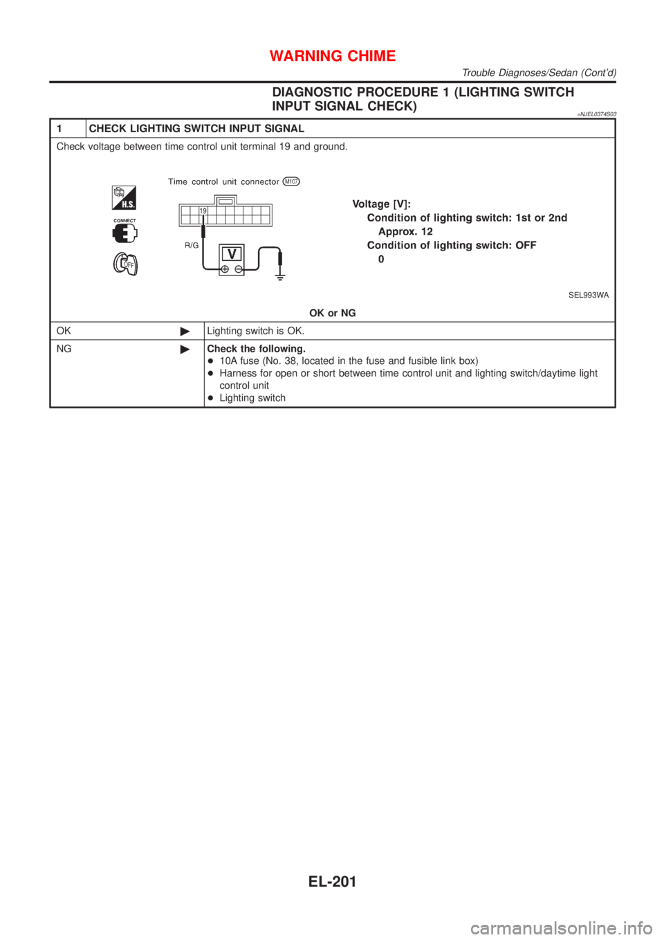
1 CHECK LIGHTING SWITCH INPUT SIGNAL
Check voltage between time control unit terminal 19 and ground.
SEL993WA
OK or NG
OK©Lighting switch is OK.
NG©Check the following.
+10A fuse (No. 38, located in the fuse and fusible link box)
+Harness for open or short between time control unit and lighting switch/daytime light
control unit
+Lighting switch
WARNING CHIME
Trouble Diagnoses/Sedan (Cont'd)
EL-201