2001 NISSAN ALMERA height adjustment
[x] Cancel search: height adjustmentPage 456 of 2898
SAT874DA
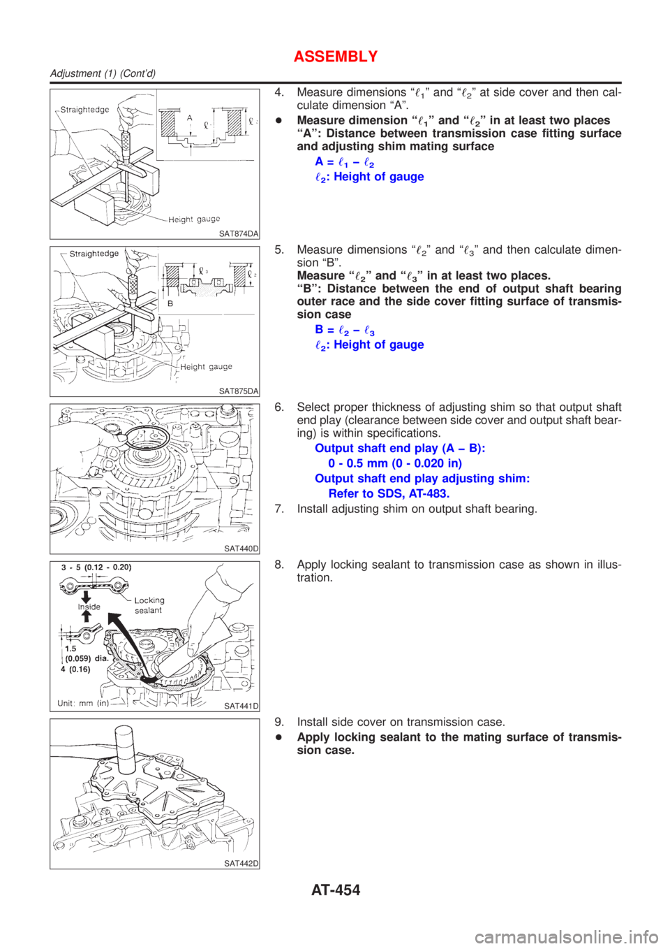
4. Measure dimensions ª!1º and ª!2º at side cover and then cal-
culate dimension ªAº.
+Measure dimension ª!
1º and ª!2º in at least two places
ªAº: Distance between transmission case fitting surface
and adjusting shim mating surface
A=!
1þ!2
!2: Height of gauge
SAT875DA
5. Measure dimensions ª!2º and ª!3º and then calculate dimen-
sion ªBº.
Measure ª!
2º and ª!3º in at least two places.
ªBº: Distance between the end of output shaft bearing
outer race and the side cover fitting surface of transmis-
sion case
B=!
2þ!3
!2: Height of gauge
SAT440D
6. Select proper thickness of adjusting shim so that output shaft
end play (clearance between side cover and output shaft bear-
ing) is within specifications.
Output shaft end play (A þ B):
0 - 0.5 mm (0 - 0.020 in)
Output shaft end play adjusting shim:
Refer to SDS, AT-483.
7. Install adjusting shim on output shaft bearing.
SAT441D
8. Apply locking sealant to transmission case as shown in illus-
tration.
SAT442D
9. Install side cover on transmission case.
+Apply locking sealant to the mating surface of transmis-
sion case.
ASSEMBLY
Adjustment (1) (Cont'd)
AT-454
Page 528 of 2898
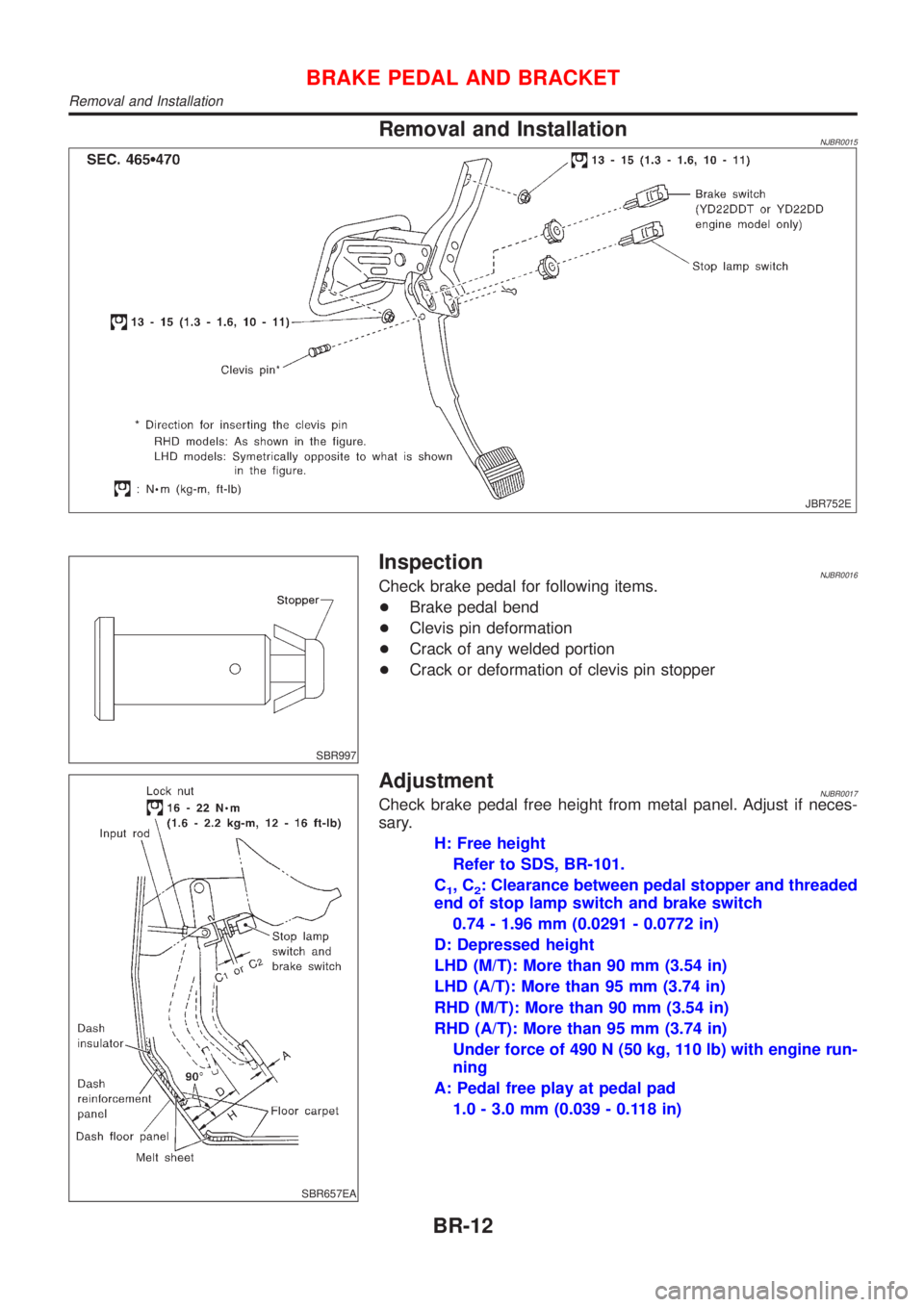
Removal and InstallationNJBR0015
JBR752E
SBR997
InspectionNJBR0016Check brake pedal for following items.
+Brake pedal bend
+Clevis pin deformation
+Crack of any welded portion
+Crack or deformation of clevis pin stopper
SBR657EA
AdjustmentNJBR0017Check brake pedal free height from metal panel. Adjust if neces-
sary.
H: Free height
Refer to SDS, BR-101.
C
1,C2: Clearance between pedal stopper and threaded
end of stop lamp switch and brake switch
0.74 - 1.96 mm (0.0291 - 0.0772 in)
D: Depressed height
LHD (M/T): More than 90 mm (3.54 in)
LHD (A/T): More than 95 mm (3.74 in)
RHD (M/T): More than 90 mm (3.54 in)
RHD (A/T): More than 95 mm (3.74 in)
Under force of 490 N (50 kg, 110 lb) with engine run-
ning
A: Pedal free play at pedal pad
1.0 - 3.0 mm (0.039 - 0.118 in)
BRAKE PEDAL AND BRACKET
Removal and Installation
BR-12
Page 529 of 2898
SBR229E
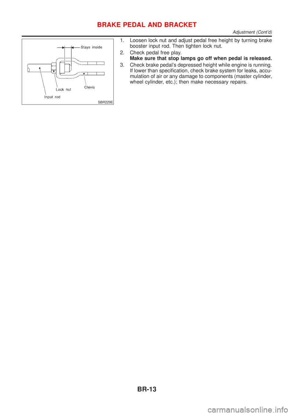
1. Loosen lock nut and adjust pedal free height by turning brake
booster input rod. Then tighten lock nut.
2. Check pedal free play.
Make sure that stop lamps go off when pedal is released.
3. Check brake pedal's depressed height while engine is running.
If lower than specification, check brake system for leaks, accu-
mulation of air or any damage to components (master cylinder,
wheel cylinder, etc.); then make necessary repairs.
BRAKE PEDAL AND BRACKET
Adjustment (Cont'd)
BR-13
Page 686 of 2898
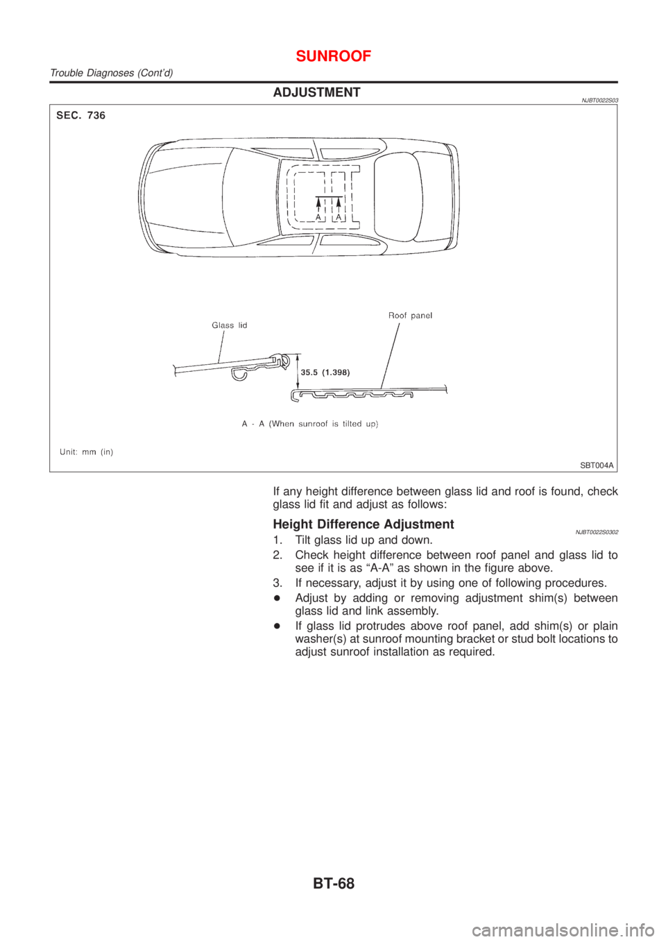
ADJUSTMENTNJBT0022S03
SBT004A
If any height difference between glass lid and roof is found, check
glass lid fit and adjust as follows:
Height Difference AdjustmentNJBT0022S03021. Tilt glass lid up and down.
2. Check height difference between roof panel and glass lid to
see if it is as ªA-Aº as shown in the figure above.
3. If necessary, adjust it by using one of following procedures.
+Adjust by adding or removing adjustment shim(s) between
glass lid and link assembly.
+If glass lid protrudes above roof panel, add shim(s) or plain
washer(s) at sunroof mounting bracket or stud bolt locations to
adjust sunroof installation as required.
SUNROOF
Trouble Diagnoses (Cont'd)
BT-68
Page 723 of 2898
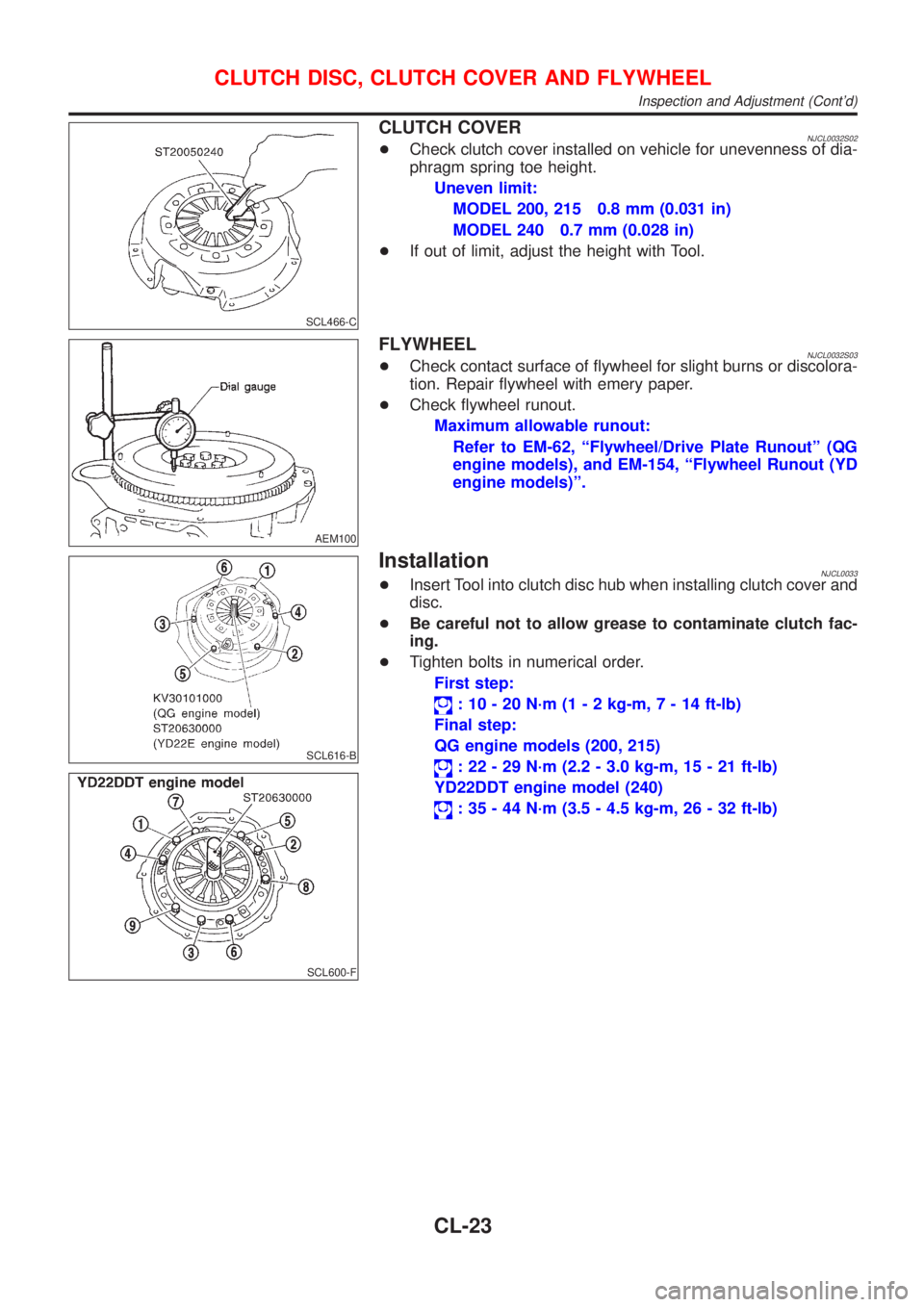
SCL466-C
CLUTCH COVERNJCL0032S02+Check clutch cover installed on vehicle for unevenness of dia-
phragm spring toe height.
Uneven limit:
MODEL 200, 215 0.8 mm (0.031 in)
MODEL 240 0.7 mm (0.028 in)
+If out of limit, adjust the height with Tool.
AEM100
FLYWHEELNJCL0032S03+Check contact surface of flywheel for slight burns or discolora-
tion. Repair flywheel with emery paper.
+Check flywheel runout.
Maximum allowable runout:
Refer to EM-62, ªFlywheel/Drive Plate Runoutº (QG
engine models), and EM-154, ªFlywheel Runout (YD
engine models)º.
SCL616-B
SCL600-F
InstallationNJCL0033+Insert Tool into clutch disc hub when installing clutch cover and
disc.
+Be careful not to allow grease to contaminate clutch fac-
ing.
+Tighten bolts in numerical order.
First step:
: 10 - 20 N´m (1 - 2 kg-m,7-14ft-lb)
Final step:
QG engine models (200, 215)
: 22 - 29 N´m (2.2 - 3.0 kg-m, 15 - 21 ft-lb)
YD22DDT engine model (240)
: 35 - 44 N´m (3.5 - 4.5 kg-m, 26 - 32 ft-lb)
CLUTCH DISC, CLUTCH COVER AND FLYWHEEL
Inspection and Adjustment (Cont'd)
CL-23
Page 1650 of 2898
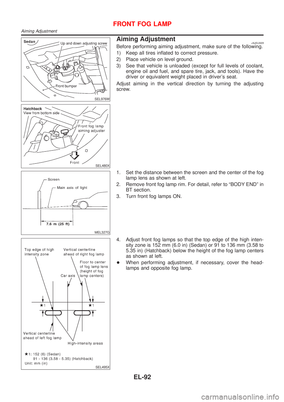
SEL976W
SEL480X
Aiming Adjustment=NJEL0029Before performing aiming adjustment, make sure of the following.
1) Keep all tires inflated to correct pressure.
2) Place vehicle on level ground.
3) See that vehicle is unloaded (except for full levels of coolant,
engine oil and fuel, and spare tire, jack, and tools). Have the
driver or equivalent weight placed in driver's seat.
Adjust aiming in the vertical direction by turning the adjusting
screw.
MEL327G
1. Set the distance between the screen and the center of the fog
lamp lens as shown at left.
2. Remove front fog lamp rim. For detail, refer to ªBODY ENDº in
BT section.
3. Turn front fog lamps ON.
SEL495X
4. Adjust front fog lamps so that the top edge of the high inten-
sity zone is 152 mm (6.0 in) (Sedan) or 91 to 136 mm (3.58 to
5.35 in) (Hatchback) below the height of the fog lamp centers
as shown at left.
+When performing adjustment, if necessary, cover the head-
lamps and opposite fog lamp.
FRONT FOG LAMP
Aiming Adjustment
EL-92
Page 2503 of 2898

Headlining - See Roof trim ........................ BT-43
Heated oxygen sensor (HO2S)
(front) .......... EC-216, 224, 230, 236, 245, 450
Heated oxygen sensor (HO2S) heater
(front) ........................................... EC-252, 457
Heated oxygen sensor (HO2S) heater
(rear) ............................................ EC-291, 469
Heated oxygen sensor (rear) ......... EC-258, 267,
275, 284, 462
Heated seat ............................................. EL-288
Height (Dimensions) ................................... GI-43
High clutch ............................................... AT-407
Hood ............................................................ BT-7
Horn ......................................................... EL-234
How to erase DTC for OBD system .. EC-70, 73,
627
I
IACV-AAC valve .............................. EC-376, 511
IATS - Wiring diagram .................... EC-196, 444
IGN/SG - Wiring diagram ........................ EC-548
ILL - Wiring diagram ................................ EL-112
INJECT - Wiring diagram ........................ EC-542
INT/L - Wiring diagram .................... EL-141, 143
IVC - Wiring diagram ...................... EC-395, 527
Identification plate ...................................... GI-40
Idle air control (IAC) system ........... EC-376, 511
Idle air control valve (IACV) ............ EC-376, 511
Idle speed ......................................... EC-43, 641
Ignition timing ............................................ EC-43
Illumination ............................................... EL-108
Injection nozzle ....................................... EC-614
Injector removal and installation ............... EC-41
Input shaft (FF M/T) ............... MT-36, 64, 93, 98
Instrument panel ........................................ BT-25
Intake air temperature sensor ......... EC-194, 442
Intake valve timing control solenoid
valve ............................................ EC-393, 526
Interior lamp on-off control .............. EL-116, 128
Interior lamp ............................................. EL-115
Interior ........................................................ BT-31
J
Jacking points ............................................ GI-45
Joint connector (J/C) ............................... EL-583
Junction box (J/B) .................................... EL-577
K
Keyless entry system - See Multi-remote control
system ..................................................... EL-392
Knock sensor (KS) .......................... EC-324, 325
Knuckle spindle ........................................... AX-5
L
LOAD - Wiring diagram .......................... EC-579
Length (Dimensions) .................................. GI-43
License lamp ............................................. EL-81
Lifting points ............................................... GI-46
Line pressure solenoid valve ................... AT-232
Line pressure test (A/T) ............................. AT-84
Liquid gasket application ...................... EM-4, 77
Location of electrical units ....................... EL-517
Lock, door .................................................. BT-21
Low and reverse brake ............................ AT-419
Lubricant (R134a) A/C .............................. HA-80
Lubricants ................................................. MA-16
Lubrication circuit (engine) .................... LC-4, 27
M
M/T major overhaul ....................... MT-30, 54, 92
M/T removal and installation ..................... MT-23
MAFS - Wiring diagram .................. EC-189, 673
MAIN - Wiring diagram ................... EC-178, 666
MAJOR OVERHALL ................................ AT-357
METER - Wiring diagram ........................ EL-151
MIL & Data link connectors circuit .......... EC-591
MIL/DL - Wiring diagram ................. EC-591, 831
MIRROR - Wiring diagram .............. EL-294, 295
Magnet clutch ............................................ HA-83
Mainshaft (M/T) .................... MT-39, 69, 93, 103
Malfunction indicator lamp (MIL) ...... EC-74, 628
Manual air conditioner - Wiring
diagram .................................................. HA-27
Manual transaxle number .......................... GI-42
Mass air flow sensor (MAFS) ......... EC-187, 673
Master cylinder (brake) ............................. BR-14
Master cylinder (clutch) ............................. CL-11
Meter ........................................................ EL-144
Mirror defogger ........................................ EL-240
Mirror, door ................................................ BT-75
Misfire ...................................................... EC-318
Mode door control linkage
adjustment ............................................. HA-41
Model variation ........................................... GI-38
Molding - See Exterior ............................... BT-47
Multi-remote control system .................... EL-392
Multiport fuel injection (MFI) system ......... EC-32
Multiport fuel injection precautions ............... GI-6
N
NATS (Nissan Anti-theft System)
precautions ................................................... GI-3
NATS (Nissan Anti-theft System) ............ EL-422
NATS - Wiring diagram ................... EL-425, 427
NVH troubleshooting (AX) ........................... AX-3
NVH troubleshooting (BR) .......................... BR-7
NVH troubleshooting (MT) ........................ MT-13
NVH troubleshooting (ST) ........................... ST-5
ALPHABETICAL INDEX
IDX-5
Page 2505 of 2898

Seat, rear ................................................... BT-60
Self-diagnostic results ....................... EC-74, 628
Shift control components (M/T) .... MT-32, 56, 94
Shift fork (M/T) .............................. MT-32, 56, 94
Shift lever .................................................. MT-29
Shift lock system ...................................... AT-343
Shift schedule .......................................... AT-470
Shift solenoid valve A (A/T) ..... AT-204, 209, 222
Shift solenoid valve B (A/T) ............. AT-204, 209
Shock absorber (front) .............................. SU-10
Shock absorber (rear) ............................... SU-21
Side air bag ........................................ RS-36, 38
Side trim .................................................... BT-31
Spare tire size ............................................ GI-43
Speedometer ........................................... EL-144
Spiral cable ............................................... RS-29
Spot lamp ................................................ EL-141
Spring (Wheelarch) height .......................... SU-6
Stabilizer bar (front) ................................... SU-11
Stall test (A/T) ............................................ AT-80
Standardized relay ....................................... EL-8
Start signal ...................................... EC-557, 823
Starter ....................................................... SC-18
Starting system ......................................... SC-13
Steering linkage ......................................... ST-16
Steering switch .......................................... EL-59
Steering wheel and column ....................... ST-11
Steering wheel play ..................................... ST-6
Steering wheel turning force ....................... ST-8
Stop lamp .................................................. EL-85
Striking rod (M/T) .......................... MT-32, 56, 94
Strut (front) .................................................. SU-9
Strut (rear) ................................................. SU-20
Sub-gear (M/T) ................................... MT-31, 55
Sunroof, electric ....................................... EL-292
Sunroof ...................................................... BT-63
Super lock ................................................ EL-349
Supplemental Restraint System ............... RS-20
Supplemental restraint system - Wiring
diagram .................................................. RS-53
Swirl control valve control solenoid
valve ............................................ EC-399, 475
Symbols and abbreviations ........................ GI-10
Symptom matrix chart ..................... EC-155, 646
Synchronizer (M/T) ....................... MT-31, 55, 93
System readiness test (SRT) code ........... EC-62
T
TCM circuit diagram ................................... AT-17
TCM inspection table ............................... AT-119
TFTS - Wiring diagram ........................... EC-315
TP/SW - Wiring diagram ................. EC-387, 521
TPS - Wiring diagram ............................. EC-210
TURN - Wiring diagram ........................... EL-103
Tachometer .............................................. EL-144
Tail lamp .................................................... EL-81
Tank fuel temperature sensor ................. EC-313
Thermostat .......................................... LC-15, 41Three way catalyst precautions ................... GI-6
Three way catalyst .................................. EC-359
Throttle position sensor (TPS) ................ EC-207
Throttle position sensor
adjustment ................................... EC-100, 128
Throttle position switch ........... AT-141, 267, 341,
EC-385, 520
Throwout bearing - See Clutch release
bearing ............................................. CL-17, 20
Tie-rod ball joints ....................................... ST-20
Tie-rod ........................................................ ST-16
Tightening torque of standard bolts ........... GI-49
Timing chain ....................................... EM-23, 94
Tire size ...................................................... GI-43
Torque converter installation .................... AT-355
Tow truck towing ........................................ GI-47
Transmission case (M/T) .............. MT-30, 54, 92
Tread-FR&RR (Dimensions) ...................... GI-43
Trim ............................................................ BT-31
Trouble diagnoses ...................................... GI-31
Trunk lid finisher ........................................ BT-45
Trunk lid opener - See Trunk lid ................ BT-10
Trunk lid trim .............................................. BT-45
Trunk lid ..................................................... BT-10
Trunk room lamp ..................................... EL-141
Trunk room trim ......................................... BT-45
Turn signal lamp ........................................ EL-96
Two trip detection logic ............................. EC-59
Two-pole lift ................................................ GI-46
U
Under body ................................................ BT-80
V
VSS - Wiring diagram ..................... EC-372, 701
Vacuum hose (brake system) ................... BR-22
Vacuum hose drawing (Engine control) .... EC-30
Vacuum pump ........................................... BR-23
Valve clearance ................................ EM-44, 133
Valve guide ....................................... EM-39, 124
Valve lifter ................................................. EM-43
Valve seat ......................................... EM-41, 126
Valve spring ...................................... EM-42, 128
Vehicle speed sensor (VSS) ........... EC-370, 701
Viscosity number (SAE) ............................ MA-17
Viscous coupling (FF M/T) ........................ MT-93
W
WARN - Wiring diagram .......................... EL-190
WIP/R - Wiring diagram .................. EL-225, 227
WIPER - Wiring diagram ................. EL-217, 220
Warning chime ......................................... EL-197
Warning lamps ......................................... EL-184
Washer, front ........................................... EL-215
ALPHABETICAL INDEX
IDX-7