2001 NISSAN ALMERA tire type
[x] Cancel search: tire typePage 504 of 2898
Support BearingNJAX0018S05Make sure wheel bearing rolls freely and is free from noise, cracks,
pitting or wear.
Support Bearing BracketNJAX0018S06Check support bearing bracket for cracks with a magnetic explora-
tion or dyeing test.
ASSEMBLYNJAX0019+After drive shaft has been assembled, ensure that it
moves smoothly over its entire range without binding.
+Use NISSAN GENUINE GREASE or equivalent after every
overhaul.
SFA800
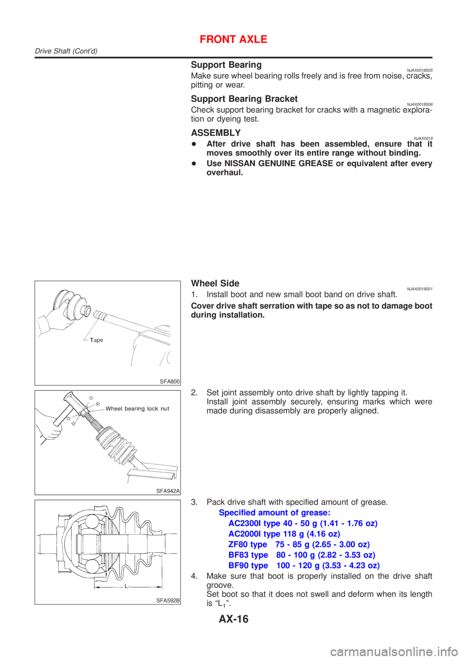
Wheel SideNJAX0019S011. Install boot and new small boot band on drive shaft.
Cover drive shaft serration with tape so as not to damage boot
during installation.
SFA942A
2. Set joint assembly onto drive shaft by lightly tapping it.
Install joint assembly securely, ensuring marks which were
made during disassembly are properly aligned.
SFA592B
3. Pack drive shaft with specified amount of grease.
Specified amount of grease:
AC2300I type 40 - 50 g (1.41 - 1.76 oz)
AC2000I type 118 g (4.16 oz)
ZF80 type 75 - 85 g (2.65 - 3.00 oz)
BF83 type 80 - 100 g (2.82 - 3.53 oz)
BF90 type 100 - 120 g (3.53 - 4.23 oz)
4. Make sure that boot is properly installed on the drive shaft
groove.
Set boot so that it does not swell and deform when its length
is ªL
1º.
FRONT AXLE
Drive Shaft (Cont'd)
AX-16
Page 2010 of 2898
SEL504X
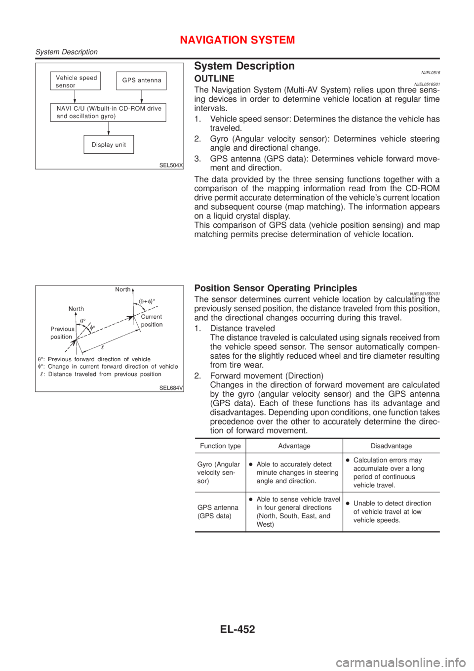
System DescriptionNJEL0516OUTLINENJEL0516S01The Navigation System (Multi-AV System) relies upon three sens-
ing devices in order to determine vehicle location at regular time
intervals.
1. Vehicle speed sensor: Determines the distance the vehicle has
traveled.
2. Gyro (Angular velocity sensor): Determines vehicle steering
angle and directional change.
3. GPS antenna (GPS data): Determines vehicle forward move-
ment and direction.
The data provided by the three sensing functions together with a
comparison of the mapping information read from the CD-ROM
drive permit accurate determination of the vehicle's current location
and subsequent course (map matching). The information appears
on a liquid crystal display.
This comparison of GPS data (vehicle position sensing) and map
matching permits precise determination of vehicle location.
SEL684V
Position Sensor Operating PrinciplesNJEL0516S0101The sensor determines current vehicle location by calculating the
previously sensed position, the distance traveled from this position,
and the directional changes occurring during this travel.
1. Distance traveled
The distance traveled is calculated using signals received from
the vehicle speed sensor. The sensor automatically compen-
sates for the slightly reduced wheel and tire diameter resulting
from tire wear.
2. Forward movement (Direction)
Changes in the direction of forward movement are calculated
by the gyro (angular velocity sensor) and the GPS antenna
(GPS data). Each of these functions has its advantage and
disadvantages. Depending upon conditions, one function takes
precedence over the other to accurately determine the direc-
tion of forward movement.
Function type Advantage Disadvantage
Gyro (Angular
velocity sen-
sor)+Able to accurately detect
minute changes in steering
angle and direction.+Calculation errors may
accumulate over a long
period of continuous
vehicle travel.
GPS antenna
(GPS data)+Able to sense vehicle travel
in four general directions
(North, South, East, and
West)+Unable to detect direction
of vehicle travel at low
vehicle speeds.
NAVIGATION SYSTEM
System Description
EL-452
Page 2728 of 2898
Precautions
SUPPLEMENTAL RESTRAINT SYSTEM (SRS) ªAIR BAGº AND ªSEAT BELT
PRE-TENSIONERº
NJRS0006The Supplemental Restraint System such as ªAIR BAGº and ªSEAT BELT PRE-TENSIONERº used along with
a seat belt, helps to reduce the risk or severity of injury to the driver and front passenger for certain types of
collision. The SRS composition which is available to NISSAN MODEL N16 is as follows (The composition
varies according to the destination and optional equipment.):
+For a frontal collision
The Supplemental Restraint System consists of driver air bag module (located in the center of the steer-
ing wheel), front passenger air bag module (located on the instrument panel on passenger side), front seat
belt pre-tensioners, a diagnosis sensor unit, warning lamp, wiring harness and spiral cable.
+For a side collision
The Supplemental Restraint System consists of front side air bag module (located in the outer side of front
seat), side air bag (satellite) sensor, diagnosis sensor unit (one of components of air bags for a frontal
collision), wiring harness, warning lamp (one of components of air bags for a frontal collision).
WARNING:
+To avoid rendering the SRS inoperative, which could increase the risk of personal injury or death
in the event of a collision which would result in air bag inflation, all maintenance should be per-
formed by an authorized NISSAN dealer.
+Improper maintenance, including incorrect removal and installation of the SRS, can lead to per-
sonal injury caused by unintentional activation of the system.
+Do not use electrical test equipment on any circuit related to the SRS unless instructed to in this
Service Manual. SRS wiring harnesses can be identified by yellow harness connector.
PRECAUTIONS FOR SRS ªAIR BAGº AND ªSEAT BELT PRE-TENSIONERº SERVICENJRS0007+Do not use electrical test equipment to check SRS circuits unless instructed to in this Service Manual.
+Before servicing the SRS, turn ignition switch ªOFFº, disconnect both battery cables and wait at least 3
minutes.
For approximately 3 minutes after the cables are removed, it is still possible for the air bag and seat belt
pre-tensioner to deploy. Therefore, do not work on any SRS connectors or wires until at least 3 minutes
have passed.
+Diagnosis sensor unit must always be installed with their arrow marks ªÜº pointing towards the front of
the vehicle for proper operation. Also check diagnosis sensor unit for cracks, deformities or rust before
installation and replace as required.
+The spiral cable must be aligned with the neutral position since its rotations are limited. Do not attempt to
turn steering wheel or column after removal of steering gear.
+Handle air bag module carefully. Always place driver and front passenger air bag modules with the pad
side facing upward and place front side air bag module standing with stud bolt side setting bottom.
+Conduct self-diagnosis to check entire SRS for proper function after replacing any components.
+After air bag inflates, the front instrument panel assembly should be replaced if damaged.
WIRING DIAGRAMS AND TROUBLE DIAGNOSISNJRS0008When you read wiring diagrams, refer to the following:
+GI-11, ªHOW TO READ WIRING DIAGRAMSº
+EL-10, ªPOWER SUPPLY ROUTINGº for power distribution circuit
When you perform trouble diagnosis, refer to the following:
+GI-32, ªHOW TO FOLLOW TEST GROUPS IN TROUBLE DIAGNOSESº
+GI-21, ªHOW TO PERFORM EFFICIENT DIAGNOSES FOR AN ELECTRICAL INCIDENTº
SUPPLEMENTAL RESTRAINT SYSTEM (SRS)
Precautions
RS-20
Page 2879 of 2898
SFA975B
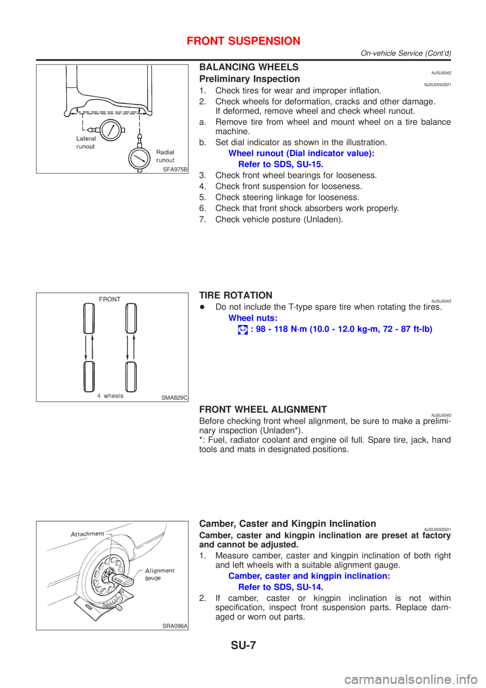
BALANCING WHEELSNJSU0042Preliminary InspectionNJSU0042S011. Check tires for wear and improper inflation.
2. Check wheels for deformation, cracks and other damage.
If deformed, remove wheel and check wheel runout.
a. Remove tire from wheel and mount wheel on a tire balance
machine.
b. Set dial indicator as shown in the illustration.
Wheel runout (Dial indicator value):
Refer to SDS, SU-15.
3. Check front wheel bearings for looseness.
4. Check front suspension for looseness.
5. Check steering linkage for looseness.
6. Check that front shock absorbers work properly.
7. Check vehicle posture (Unladen).
SMA829C
TIRE ROTATIONNJSU0043+Do not include the T-type spare tire when rotating the tires.
Wheel nuts:
: 98 - 118 N´m (10.0 - 12.0 kg-m, 72 - 87 ft-lb)
FRONT WHEEL ALIGNMENTNJSU0045Before checking front wheel alignment, be sure to make a prelimi-
nary inspection (Unladen*).
*: Fuel, radiator coolant and engine oil full. Spare tire, jack, hand
tools and mats in designated positions.
SRA096A
Camber, Caster and Kingpin InclinationNJSU0045S01Camber, caster and kingpin inclination are preset at factory
and cannot be adjusted.
1. Measure camber, caster and kingpin inclination of both right
and left wheels with a suitable alignment gauge.
Camber, caster and kingpin inclination:
Refer to SDS, SU-14.
2. If camber, caster or kingpin inclination is not within
specification, inspect front suspension parts. Replace dam-
aged or worn out parts.
FRONT SUSPENSION
On-vehicle Service (Cont'd)
SU-7
Page 2886 of 2898
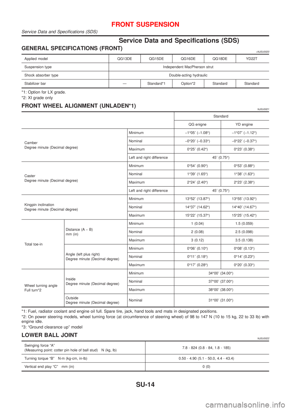
Service Data and Specifications (SDS)
GENERAL SPECIFICATIONS (FRONT)=NJSU0020
Applied model QG13DE QG15DE QG16DE QG18DE YD22T
Suspension type Independent MacPherson strut
Shock absorber type Double-acting hydraulic
Stabilizer bar Ð Standard*1 Option*2 Standard Standard
*1: Option for LX grade.
*2: XI grade only
FRONT WHEEL ALIGNMENT (UNLADEN*1)NJSU0021
Standard
QG enigne YD engine
Camber
Degree minute (Decimal degree)Minimum þ1É05¢(þ1.08É) þ1É07¢(þ1.12É)
Nominal þ0É20¢(þ0.33É) þ0É22¢(þ0.37É)
Maximum 0É25¢(0.42É) 0É23¢(0.38É)
Left and right difference 45¢(0.75É)
Caster
Degree minute (Decimal degree)Minimum 0É54¢(0.90É) 0É53¢(0.88É)
Nominal 1É39¢(1.65É) 1É38¢(1.63É)
Maximum 2É24¢(2.40É) 2É23¢(2.38É)
Left and right difference 45¢(0.75É)
Kingpin inclination
Degree minute (Decimal degree)Minimum 13É52¢(13.87É) 13É55¢(13.92É)
Nominal 14É37¢(14.62É) 14É40¢(14.67É)
Maximum 15É22¢(15.37É) 15É25¢(15.42É)
Total toe-inDistance (A þ B)
mm (in)Minimum 1 (0.04) 1.5 (0.059)
Nominal 2 (0.08) 2.5 (0.098)
Maximum 3 (0.12) 3.5 (0.138)
Angle (left plus right)
Degree minute (Decimal degree)Minimum 0É06¢(0.10É) 0É08¢(0.13É)
Nominal 0É11¢(0.18É) 0É14¢(0.23É)
Maximum 0É17¢(0.28É) 0É20¢(0.33É)
Wheel turning angle
Full turn*2Inside
Degree minute (Decimal degree)Minimum 34É00¢(34.00É)
Nominal 37É00¢(37.00É)
Maximum 38É00¢(38.00É)
Outside
Degree minute (Decimal degree)Nominal 31É00¢(31.00É)
*1: Fuel, radiator coolant and engine oil full. Spare tire, jack, hand tools and mats in designated positions.
*2: On power steering models, wheel turning force (at circumference of steering wheel) of 98 to 147 N (10 to 15 kg, 22 to 33 lb) with
engine idle.
*3: ªGround clearance upº model
LOWER BALL JOINTNJSU0022
Swinging force ªAº
(Measuring point: cotter pin hole of ball stud) N (kg, lb)7.8 - 824 (0.8 - 84, 1.8 - 185)
Turning torque ªBº N´m (kg-cm, in-lb) 0.50 - 4.90 (5.1 - 50.0, 4.4 - 43.4)
Vertical end play ªCº mm (in)0 (0)
FRONT SUSPENSION
Service Data and Specifications (SDS)
SU-14
Page 2887 of 2898
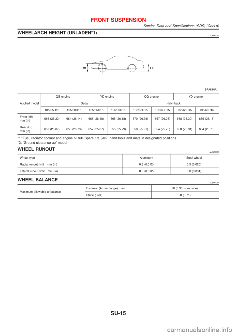
WHEELARCH HEIGHT (UNLADEN*1)NJSU0041
SFA818A
Applied modelQG engine YD engine QG engine YD engine
Sedan Hatchback
185/65R15 195/60R15 185/65R15 195/60R15 185/65R15 195/60R15 185/65R15 195/60R15
Front (Hf)
mm (in)666 (26.22) 664 (26.14) 665 (26.18) 665 (26.18) 670 (26.38) 667 (26.26) 668 (26.30) 665 (26.18)
Rear (Hr)
mm (in)657 (25.87) 655 (25.79) 657 (25.87) 655 (25.79) 658 (25.91) 654 (25.75) 658 (25.91) 654 (25.75)
*1: Fuel, radiator coolant and engine oil full. Spare tire, jack, hand tools and mats in designated positions.
*2: ªGround clearance upº model
WHEEL RUNOUTNJSU0023
Wheel typeAluminum Steel wheel
Radial runout limit mm (in) 0.3 (0.012) 0.5 (0.020)
Lateral runout limit mm (in) 0.3 (0.012) 0.8 (0.031)
WHEEL BALANCENJSU0044
Maximum allowable unbalanceDynamic (At rim flange) g (oz) 10 (0.35) (one side)
Static g (oz) 20 (0.71)
FRONT SUSPENSION
Service Data and Specifications (SDS) (Cont'd)
SU-15
Page 2897 of 2898
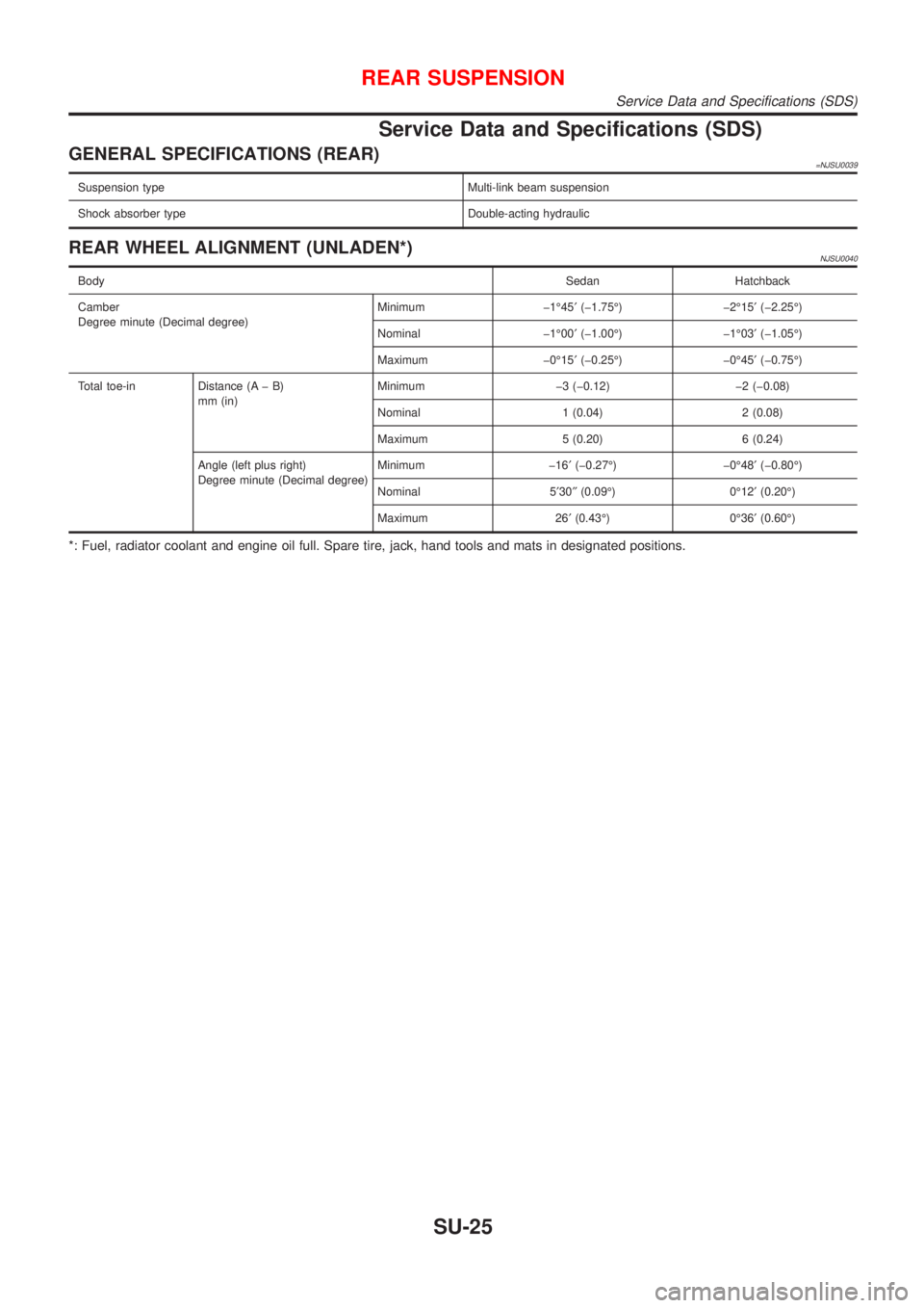
Service Data and Specifications (SDS)
GENERAL SPECIFICATIONS (REAR)=NJSU0039
Suspension type Multi-link beam suspension
Shock absorber type Double-acting hydraulic
REAR WHEEL ALIGNMENT (UNLADEN*)NJSU0040
BodySedan Hatchback
Camber
Degree minute (Decimal degree)Minimum þ1É45¢(þ1.75É) þ2É15¢(þ2.25É)
Nominal þ1É00¢(þ1.00É) þ1É03¢(þ1.05É)
Maximum þ0É15¢(þ0.25É) þ0É45¢(þ0.75É)
Total toe-in Distance (A þ B)
mm (in)Minimum þ3 (þ0.12) þ2 (þ0.08)
Nominal 1 (0.04) 2 (0.08)
Maximum 5 (0.20) 6 (0.24)
Angle (left plus right)
Degree minute (Decimal degree)Minimum þ16¢(þ0.27É) þ0É48¢(þ0.80É)
Nominal 5¢30²(0.09É) 0É12¢(0.20É)
Maximum 26¢(0.43É) 0É36¢(0.60É)
*: Fuel, radiator coolant and engine oil full. Spare tire, jack, hand tools and mats in designated positions.
REAR SUSPENSION
Service Data and Specifications (SDS)
SU-25