2001 NISSAN ALMERA heating
[x] Cancel search: heatingPage 11 of 2898

parts. Apply petroleum jelly to protect O-rings and seals, or
hold bearings and washers in place during assembly. Do not
use grease.
+Extreme care should be taken to avoid damage to O-rings,
seals and gaskets when assembling.
+After overhaul, refill the transaxle with new ATF.
+When the A/T drain plug is removed, only some of the fluid is
drained. Old A/T fluid will remain in torque converter and ATF
cooling system.
Always follow the procedures under ªChanging A/T Fluidº in the
AT section when changing A/T fluid. Refer to ªChanging A/T
Fluidº, AT-15.
Service Notice or PrecautionsNJAT0247FAIL-SAFENJAT0247S01The TCM has an electronic Fail-Safe (limp home mode). This allows the vehicle to be driven even if a major
electrical input/output device circuit is damaged.
Under Fail-Safe, the vehicle always runs in third gear, even with a shift lever position of ª1º, ª2º or ªDº. The
customer may complain of sluggish or poor acceleration.
When the ignition key is turned ªONº following Fail-Safe operation, O/D OFF indicator lamp blinks for about
8 seconds. (For GENERAL AND EXCEPT FOR EURO-OBD; ªSELF-DIAGNOSTIC PROCEDURE (WITHOUT
CONSULT-II)º, refer to AT-44 and for EURO-OBD; ªTCM SELF-DIAGNOSTIC PROCEDURE (No Tools)º, refer
to AT-63.)
Fail-Safe may occur without electrical circuit damage if the vehicle is driven under extreme conditions (such
as excessive wheel spin followed by sudden braking). To recover normal shift pattern, turn the ignition key
ªOFFº for 5 seconds, then ªONº.
The blinking of the O/D OFF indicator lamp for about 8 seconds will appear only once and be cleared. The
customer may resume normal driving conditions.
Always follow the ªWORK FLOWº [Refer to AT-73 (General and except for Euro-OBD), AT-78 (EURO-OBD).]
The SELF-DIAGNOSIS results will be as follows:
The first SELF-DIAGNOSIS will indicate damage to the vehicle speed sensor or the revolution sensor.
During the next SELF-DIAGNOSIS, performed after checking the sensor, no damages will be indicated.
TORQUE CONVERTER SERVICENJAT0247S02The torque converter should be replaced under any of the following conditions:
+External leaks in the hub weld area.
+Converter hub is scored or damaged.
+Converter pilot is broken, damaged or fits poorly into crankshaft.
+Steel particles are found after flushing the cooler and cooler lines.
+Pump is damaged or steel particles are found in the converter.
+Vehicle has TCC shudder and/or no TCC apply. Replace only after all hydraulic and electrical diagnoses
have been made. (Converter clutch material may be glazed.)
+Converter is contaminated with engine coolant containing antifreeze.
+Internal failure of stator roller clutch.
+Heavy clutch debris due to overheating (blue converter).
+Steel particles or clutch lining material found in fluid filter or on magnet when no internal parts in unit are
worn or damaged Ð indicates that lining material came from converter.
PRECAUTIONS
Precautions (Cont'd)
AT-9
Page 82 of 2898

SAT767B
A/T Fluid CheckNJAT0025FLUID LEAKAGE CHECKNJAT0025S011. Clean area suspected of leaking. Ð for example, mating sur-
face of converter housing and transmission case.
2. Start engine, apply foot brake, place selector lever in ªDº posi-
tion and wait a few minutes.
3. Stop engine.
SAT288G
4. Check for fresh leakage.
SAT638A
FLUID CONDITION CHECKNJAT0025S02
Fluid color Suspected problem
Dark or black with burned odor Wear of frictional material
Milky pink Water contamination Ð Road water
entering through filler tube or breather
Varnished fluid, light to dark brown
and tackyOxidation Ð Over or under filling, Ð
Overheating
FLUID LEVEL CHECKNJAT0025S03Refer to ªChecking A/T Fluidº, AT-15.
SAT647B
Stall TestNJAT0026STALL TEST PROCEDURENJAT0026S011. Check A/T fluid and engine oil levels. If necessary, add.
2. Drive vehicle for approx. 10 minutes or until fluid and oil reach
operating temperature.
ATF operating temperature:
50 - 80ÉC (122 - 176ÉF)
TROUBLE DIAGNOSIS Ð BASIC INSPECTION
A/T Fluid Check
AT-80
Page 729 of 2898
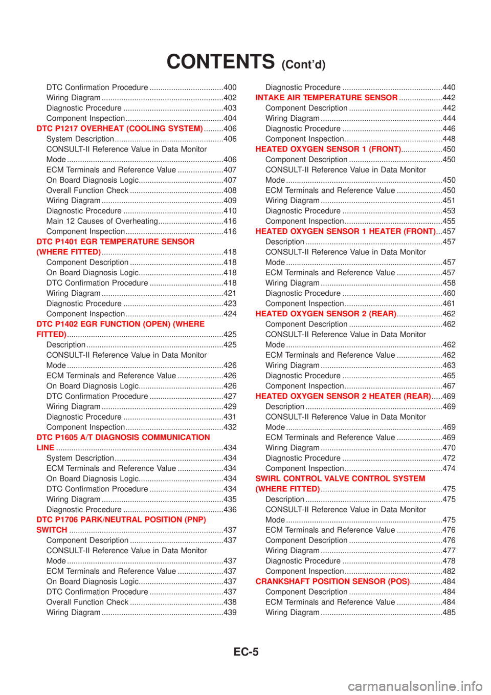
DTC Confirmation Procedure ..................................400
Wiring Diagram ........................................................402
Diagnostic Procedure ..............................................403
Component Inspection .............................................404
DTC P1217 OVERHEAT (COOLING SYSTEM).........406
System Description ..................................................406
CONSULT-II Reference Value in Data Monitor
Mode ........................................................................406
ECM Terminals and Reference Value .....................407
On Board Diagnosis Logic.......................................407
Overall Function Check ...........................................408
Wiring Diagram ........................................................409
Diagnostic Procedure ..............................................410
Main 12 Causes of Overheating..............................416
Component Inspection .............................................416
DTC P1401 EGR TEMPERATURE SENSOR
(WHERE FITTED)........................................................418
Component Description ...........................................418
On Board Diagnosis Logic.......................................418
DTC Confirmation Procedure ..................................418
Wiring Diagram ........................................................421
Diagnostic Procedure ..............................................423
Component Inspection .............................................424
DTC P1402 EGR FUNCTION (OPEN) (WHERE
FITTED)........................................................................425
Description ...............................................................425
CONSULT-II Reference Value in Data Monitor
Mode ........................................................................426
ECM Terminals and Reference Value .....................426
On Board Diagnosis Logic.......................................426
DTC Confirmation Procedure ..................................427
Wiring Diagram ........................................................429
Diagnostic Procedure ..............................................431
Component Inspection .............................................432
DTC P1605 A/T DIAGNOSIS COMMUNICATION
LINE.............................................................................434
System Description ..................................................434
ECM Terminals and Reference Value .....................434
On Board Diagnosis Logic.......................................434
DTC Confirmation Procedure ..................................434
Wiring Diagram ........................................................435
Diagnostic Procedure ..............................................436
DTC P1706 PARK/NEUTRAL POSITION (PNP)
SWITCH.......................................................................437
Component Description ...........................................437
CONSULT-II Reference Value in Data Monitor
Mode ........................................................................437
ECM Terminals and Reference Value .....................437
On Board Diagnosis Logic.......................................437
DTC Confirmation Procedure ..................................437
Overall Function Check ...........................................438
Wiring Diagram ........................................................439Diagnostic Procedure ..............................................440
INTAKE AIR TEMPERATURE SENSOR....................442
Component Description ...........................................442
Wiring Diagram ........................................................444
Diagnostic Procedure ..............................................446
Component Inspection .............................................448
HEATED OXYGEN SENSOR 1 (FRONT)...................450
Component Description ...........................................450
CONSULT-II Reference Value in Data Monitor
Mode ........................................................................450
ECM Terminals and Reference Value .....................450
Wiring Diagram ........................................................451
Diagnostic Procedure ..............................................453
Component Inspection .............................................455
HEATED OXYGEN SENSOR 1 HEATER (FRONT)...457
Description ...............................................................457
CONSULT-II Reference Value in Data Monitor
Mode ........................................................................457
ECM Terminals and Reference Value .....................457
Wiring Diagram ........................................................458
Diagnostic Procedure ..............................................460
Component Inspection .............................................461
HEATED OXYGEN SENSOR 2 (REAR).....................462
Component Description ...........................................462
CONSULT-II Reference Value in Data Monitor
Mode ........................................................................462
ECM Terminals and Reference Value .....................462
Wiring Diagram ........................................................463
Diagnostic Procedure ..............................................465
Component Inspection .............................................467
HEATED OXYGEN SENSOR 2 HEATER (REAR).....469
Description ...............................................................469
CONSULT-II Reference Value in Data Monitor
Mode ........................................................................469
ECM Terminals and Reference Value .....................469
Wiring Diagram ........................................................470
Diagnostic Procedure ..............................................472
Component Inspection .............................................474
SWIRL CONTROL VALVE CONTROL SYSTEM
(WHERE FITTED)........................................................475
Description ...............................................................475
CONSULT-II Reference Value in Data Monitor
Mode ........................................................................475
ECM Terminals and Reference Value .....................476
Component Description ...........................................476
Wiring Diagram ........................................................477
Diagnostic Procedure ..............................................478
Component Inspection .............................................482
CRANKSHAFT POSITION SENSOR (POS)...............484
Component Description ...........................................484
ECM Terminals and Reference Value .....................484
Wiring Diagram ........................................................485
CONTENTS(Cont'd)
EC-5
Page 732 of 2898
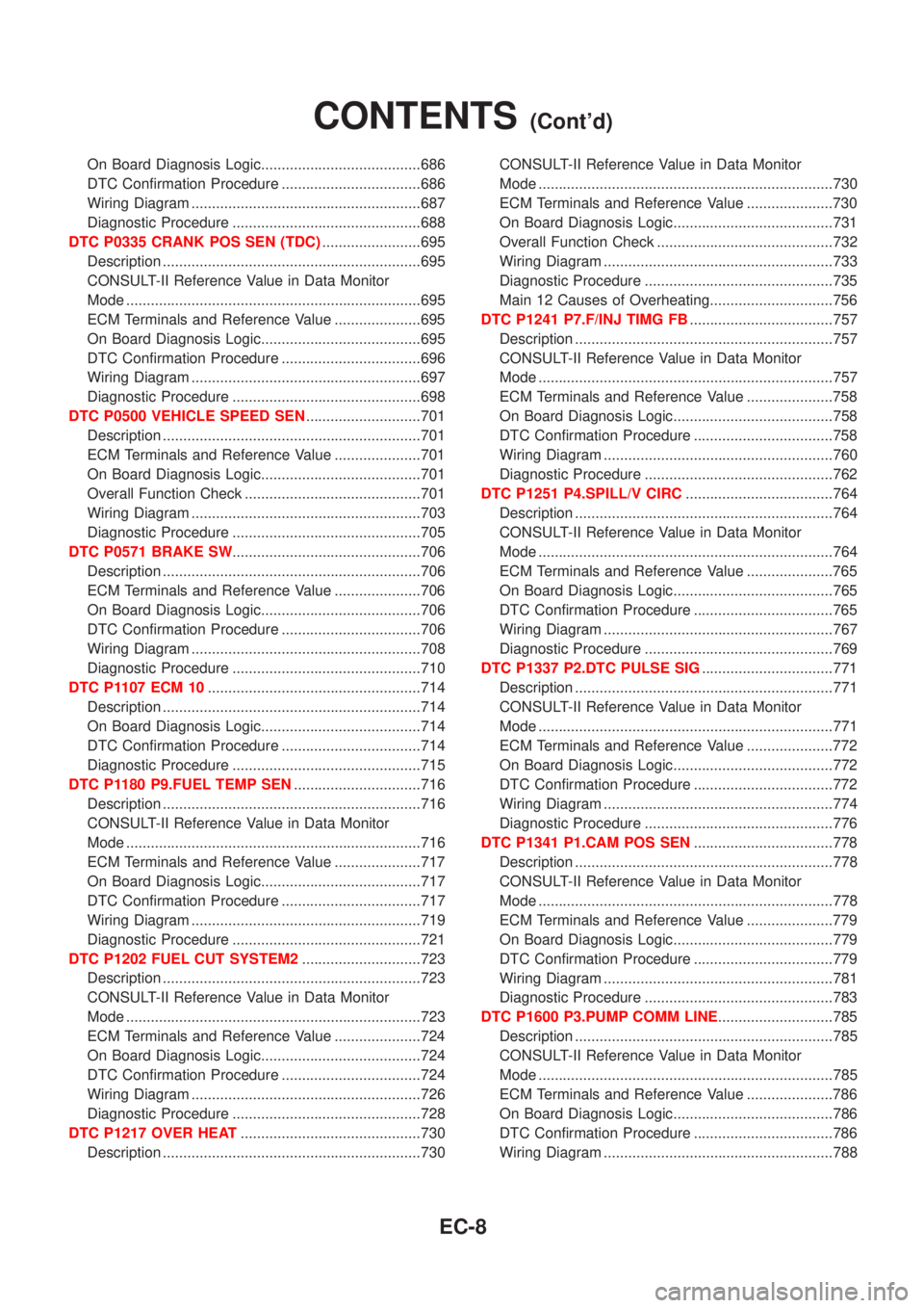
On Board Diagnosis Logic.......................................686
DTC Confirmation Procedure ..................................686
Wiring Diagram ........................................................687
Diagnostic Procedure ..............................................688
DTC P0335 CRANK POS SEN (TDC)........................695
Description ...............................................................695
CONSULT-II Reference Value in Data Monitor
Mode ........................................................................695
ECM Terminals and Reference Value .....................695
On Board Diagnosis Logic.......................................695
DTC Confirmation Procedure ..................................696
Wiring Diagram ........................................................697
Diagnostic Procedure ..............................................698
DTC P0500 VEHICLE SPEED SEN............................701
Description ...............................................................701
ECM Terminals and Reference Value .....................701
On Board Diagnosis Logic.......................................701
Overall Function Check ...........................................701
Wiring Diagram ........................................................703
Diagnostic Procedure ..............................................705
DTC P0571 BRAKE SW..............................................706
Description ...............................................................706
ECM Terminals and Reference Value .....................706
On Board Diagnosis Logic.......................................706
DTC Confirmation Procedure ..................................706
Wiring Diagram ........................................................708
Diagnostic Procedure ..............................................710
DTC P1107 ECM 10....................................................714
Description ...............................................................714
On Board Diagnosis Logic.......................................714
DTC Confirmation Procedure ..................................714
Diagnostic Procedure ..............................................715
DTC P1180 P9.FUEL TEMP SEN...............................716
Description ...............................................................716
CONSULT-II Reference Value in Data Monitor
Mode ........................................................................716
ECM Terminals and Reference Value .....................717
On Board Diagnosis Logic.......................................717
DTC Confirmation Procedure ..................................717
Wiring Diagram ........................................................719
Diagnostic Procedure ..............................................721
DTC P1202 FUEL CUT SYSTEM2.............................723
Description ...............................................................723
CONSULT-II Reference Value in Data Monitor
Mode ........................................................................723
ECM Terminals and Reference Value .....................724
On Board Diagnosis Logic.......................................724
DTC Confirmation Procedure ..................................724
Wiring Diagram ........................................................726
Diagnostic Procedure ..............................................728
DTC P1217 OVER HEAT............................................730
Description ...............................................................730CONSULT-II Reference Value in Data Monitor
Mode ........................................................................730
ECM Terminals and Reference Value .....................730
On Board Diagnosis Logic.......................................731
Overall Function Check ...........................................732
Wiring Diagram ........................................................733
Diagnostic Procedure ..............................................735
Main 12 Causes of Overheating..............................756
DTC P1241 P7.F/INJ TIMG FB...................................757
Description ...............................................................757
CONSULT-II Reference Value in Data Monitor
Mode ........................................................................757
ECM Terminals and Reference Value .....................758
On Board Diagnosis Logic.......................................758
DTC Confirmation Procedure ..................................758
Wiring Diagram ........................................................760
Diagnostic Procedure ..............................................762
DTC P1251 P4.SPILL/V CIRC....................................764
Description ...............................................................764
CONSULT-II Reference Value in Data Monitor
Mode ........................................................................764
ECM Terminals and Reference Value .....................765
On Board Diagnosis Logic.......................................765
DTC Confirmation Procedure ..................................765
Wiring Diagram ........................................................767
Diagnostic Procedure ..............................................769
DTC P1337 P2.DTC PULSE SIG................................771
Description ...............................................................771
CONSULT-II Reference Value in Data Monitor
Mode ........................................................................771
ECM Terminals and Reference Value .....................772
On Board Diagnosis Logic.......................................772
DTC Confirmation Procedure ..................................772
Wiring Diagram ........................................................774
Diagnostic Procedure ..............................................776
DTC P1341 P1.CAM POS SEN..................................778
Description ...............................................................778
CONSULT-II Reference Value in Data Monitor
Mode ........................................................................778
ECM Terminals and Reference Value .....................779
On Board Diagnosis Logic.......................................779
DTC Confirmation Procedure ..................................779
Wiring Diagram ........................................................781
Diagnostic Procedure ..............................................783
DTC P1600 P3.PUMP COMM LINE............................785
Description ...............................................................785
CONSULT-II Reference Value in Data Monitor
Mode ........................................................................785
ECM Terminals and Reference Value .....................786
On Board Diagnosis Logic.......................................786
DTC Confirmation Procedure ..................................786
Wiring Diagram ........................................................788
CONTENTS(Cont'd)
EC-8
Page 1041 of 2898
4 DETECT MALFUNCTIONING PART
Check the following.
+COMBINATION METER connectors
+Harness connectors B38, M81
+Harness for open or short between fuel level sensor unit to ground
©Repair harness or connector.
5 CHECK FUEL TANK TEMPERATURE SENSOR
Refer to ªComponent Inspectionº, EC-317.
OK or NG
OK©GO TO 6.
NG©Replace fuel tank temperature sensor.
6 CHECK INTERMITTENT INCIDENT
Perform ªTROUBLE DIAGNOSIS FOR INTERMITTENT INCIDENTº, EC-177.
©INSPECTION END
SEF934WA
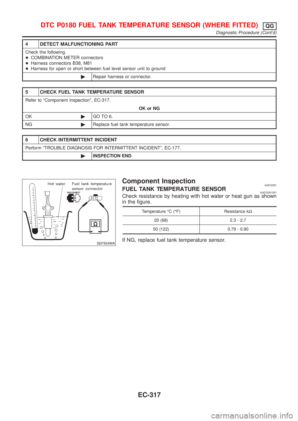
Component InspectionNJEC0201FUEL TANK TEMPERATURE SENSORNJEC0201S01Check resistance by heating with hot water or heat gun as shown
in the figure.
Temperature ÉC (ÉF) Resistance kW
20 (68) 2.3 - 2.7
50 (122) 0.79 - 0.90
If NG, replace fuel tank temperature sensor.
DTC P0180 FUEL TANK TEMPERATURE SENSOR (WHERE FITTED)QG
Diagnostic Procedure (Cont'd)
EC-317
Page 1131 of 2898
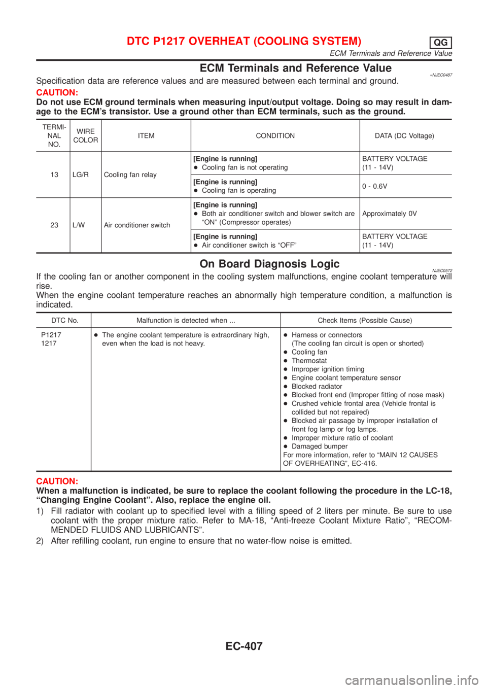
ECM Terminals and Reference Value=NJEC0487Specification data are reference values and are measured between each terminal and ground.
CAUTION:
Do not use ECM ground terminals when measuring input/output voltage. Doing so may result in dam-
age to the ECM's transistor. Use a ground other than ECM terminals, such as the ground.
TERMI-
NAL
NO.WIRE
COLORITEM CONDITION DATA (DC Voltage)
13 LG/R Cooling fan relay[Engine is running]
+Cooling fan is not operatingBATTERY VOLTAGE
(11 - 14V)
[Engine is running]
+Cooling fan is operating0 - 0.6V
23 L/W Air conditioner switch[Engine is running]
+Both air conditioner switch and blower switch are
ªONº (Compressor operates)Approximately 0V
[Engine is running]
+Air conditioner switch is ªOFFºBATTERY VOLTAGE
(11 - 14V)
On Board Diagnosis LogicNJEC0572If the cooling fan or another component in the cooling system malfunctions, engine coolant temperature will
rise.
When the engine coolant temperature reaches an abnormally high temperature condition, a malfunction is
indicated.
DTC No. Malfunction is detected when ... Check Items (Possible Cause)
P1217
1217+The engine coolant temperature is extraordinary high,
even when the load is not heavy.+Harness or connectors
(The cooling fan circuit is open or shorted)
+Cooling fan
+Thermostat
+Improper ignition timing
+Engine coolant temperature sensor
+Blocked radiator
+Blocked front end (Improper fitting of nose mask)
+Crushed vehicle frontal area (Vehicle frontal is
collided but not repaired)
+Blocked air passage by improper installation of
front fog lamp or fog lamps.
+Improper mixture ratio of coolant
+Damaged bumper
For more information, refer to ªMAIN 12 CAUSES
OF OVERHEATINGº, EC-416.
CAUTION:
When a malfunction is indicated, be sure to replace the coolant following the procedure in the LC-18,
ªChanging Engine Coolantº. Also, replace the engine oil.
1) Fill radiator with coolant up to specified level with a filling speed of 2 liters per minute. Be sure to use
coolant with the proper mixture ratio. Refer to MA-18, ªAnti-freeze Coolant Mixture Ratioº, ªRECOM-
MENDED FLUIDS AND LUBRICANTSº.
2) After refilling coolant, run engine to ensure that no water-flow noise is emitted.
DTC P1217 OVERHEAT (COOLING SYSTEM)QG
ECM Terminals and Reference Value
EC-407
Page 1139 of 2898
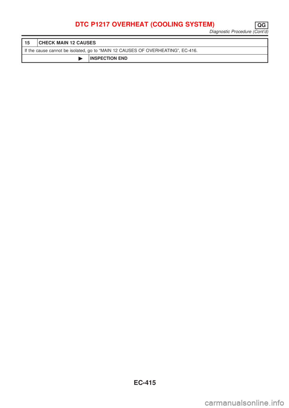
15 CHECK MAIN 12 CAUSES
If the cause cannot be isolated, go to ªMAIN 12 CAUSES OF OVERHEATINGº, EC-416.
©INSPECTION END
DTC P1217 OVERHEAT (COOLING SYSTEM)QG
Diagnostic Procedure (Cont'd)
EC-415
Page 1140 of 2898
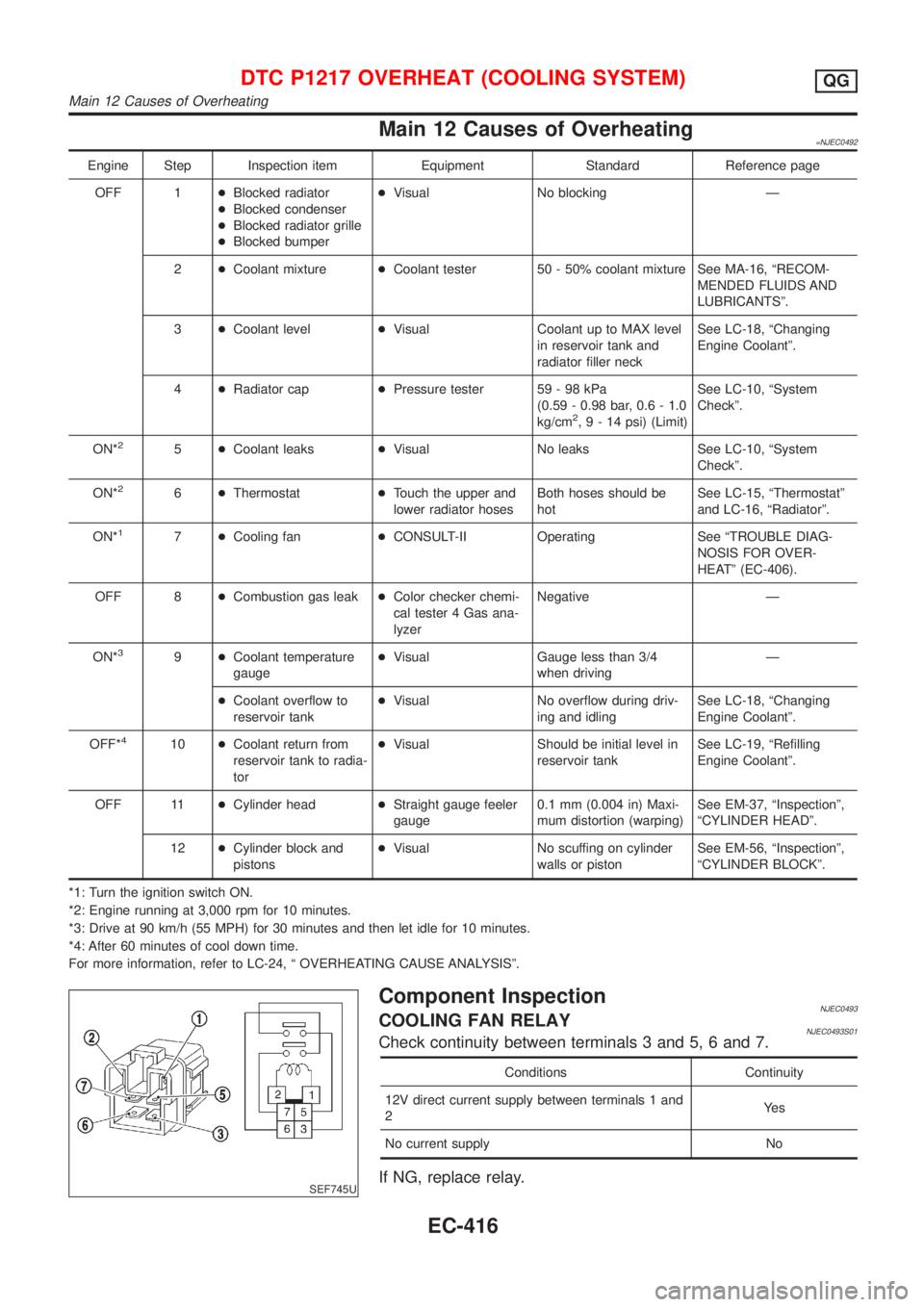
Main 12 Causes of Overheating=NJEC0492
Engine Step Inspection item Equipment Standard Reference page
OFF 1+Blocked radiator
+Blocked condenser
+Blocked radiator grille
+Blocked bumper+Visual No blocking Ð
2+Coolant mixture+Coolant tester 50 - 50% coolant mixture See MA-16, ªRECOM-
MENDED FLUIDS AND
LUBRICANTSº.
3+Coolant level+Visual Coolant up to MAX level
in reservoir tank and
radiator filler neckSee LC-18, ªChanging
Engine Coolantº.
4+Radiator cap+Pressure tester 59 - 98 kPa
(0.59 - 0.98 bar, 0.6 - 1.0
kg/cm
2,9-14psi) (Limit)See LC-10, ªSystem
Checkº.
ON*
25+Coolant leaks+Visual No leaks See LC-10, ªSystem
Checkº.
ON*
26+Thermostat+Touch the upper and
lower radiator hosesBoth hoses should be
hotSee LC-15, ªThermostatº
and LC-16, ªRadiatorº.
ON*
17+Cooling fan+CONSULT-II Operating See ªTROUBLE DIAG-
NOSIS FOR OVER-
HEATº (EC-406).
OFF 8+Combustion gas leak+Color checker chemi-
cal tester 4 Gas ana-
lyzerNegative Ð
ON*
39+Coolant temperature
gauge+Visual Gauge less than 3/4
when drivingÐ
+Coolant overflow to
reservoir tank+Visual No overflow during driv-
ing and idlingSee LC-18, ªChanging
Engine Coolantº.
OFF*
410+Coolant return from
reservoir tank to radia-
tor+Visual Should be initial level in
reservoir tankSee LC-19, ªRefilling
Engine Coolantº.
OFF 11+Cylinder head+Straight gauge feeler
gauge0.1 mm (0.004 in) Maxi-
mum distortion (warping)See EM-37, ªInspectionº,
ªCYLINDER HEADº.
12+Cylinder block and
pistons+Visual No scuffing on cylinder
walls or pistonSee EM-56, ªInspectionº,
ªCYLINDER BLOCKº.
*1: Turn the ignition switch ON.
*2: Engine running at 3,000 rpm for 10 minutes.
*3: Drive at 90 km/h (55 MPH) for 30 minutes and then let idle for 10 minutes.
*4: After 60 minutes of cool down time.
For more information, refer to LC-24, ª OVERHEATING CAUSE ANALYSISº.
SEF745U
Component InspectionNJEC0493COOLING FAN RELAYNJEC0493S01Check continuity between terminals 3 and 5, 6 and 7.
Conditions Continuity
12V direct current supply between terminals 1 and
2Ye s
No current supply No
If NG, replace relay.
DTC P1217 OVERHEAT (COOLING SYSTEM)QG
Main 12 Causes of Overheating
EC-416