2001 NISSAN ALMERA heating
[x] Cancel search: heatingPage 1455 of 2898
![NISSAN ALMERA 2001 Service Manual TERMI-
NAL
NO.WIRE
COLORITEM CONDITION DATA(DC Voltage)
221 LG/B Cooling fan relay (High)[Engine is running]
+Cooling fans are not operating
+Cooling fans are operating at low speedBATTERY VOLTAGE
(11 NISSAN ALMERA 2001 Service Manual TERMI-
NAL
NO.WIRE
COLORITEM CONDITION DATA(DC Voltage)
221 LG/B Cooling fan relay (High)[Engine is running]
+Cooling fans are not operating
+Cooling fans are operating at low speedBATTERY VOLTAGE
(11](/manual-img/5/57348/w960_57348-1454.png)
TERMI-
NAL
NO.WIRE
COLORITEM CONDITION DATA(DC Voltage)
221 LG/B Cooling fan relay (High)[Engine is running]
+Cooling fans are not operating
+Cooling fans are operating at low speedBATTERY VOLTAGE
(11 - 14V)
[Engine is running]
+Cooling fans are operating at high speedApproximately 0.1V
On Board Diagnosis LogicNJEC0663This diagnosis continuously monitors the engine coolant temperature.
If the cooling fan or another component in the cooling system malfunctions, engine coolant temperature will
rise.
When the engine coolant temperature reaches an abnormally high temperature condition, a malfunction is
indicated.
DTC Malfunction is detected when ... Check Items (Possible Cause)
P1217
0208+Cooling fan does not operate properly (Overheat).
+Cooling fan system does not operate properly
(Overheat).
+Engine coolant was not added to the system using
the proper filling method.+Harness or connectors
(The cooling fan circuit is open or shorted.)
+Cooling fan
+Radiator hose
+Radiator
+Radiator cap
+Water pump
+Thermostat
+Engine coolant temperature sensor
For more information, refer to ªMAIN 12 CAUSES OF
OVERHEATINGº, EC-756.
CAUTION:
When a malfunction is indicated, be sure to replace the coolant following the procedure in the LC-44,
ªChanging Engine Coolantº. Also, replace the engine oil.
1) Fill radiator with coolant up to specified level with a filling speed of 2 liters per minute. Be sure
to use coolant with the proper mixture ratio. Refer to MA-18, ªEngine Coolant Mixture Ratioº.
2) After refilling coolant, run engine to ensure that no water-flow noise is emitted.
DTC P1217 OVER HEATYD
ECM Terminals and Reference Value (Cont'd)
EC-731
Page 1464 of 2898
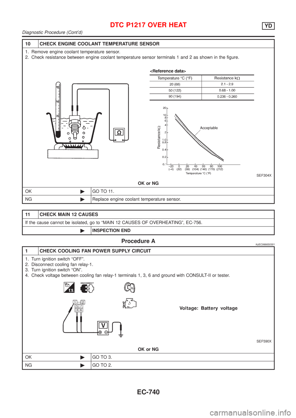
10 CHECK ENGINE COOLANT TEMPERATURE SENSOR
1. Remove engine coolant temperature sensor.
2. Check resistance between engine coolant temperature sensor terminals 1 and 2 as shown in the figure.
SEF304X
OK or NG
OK©GO TO 11.
NG©Replace engine coolant temperature sensor.
11 CHECK MAIN 12 CAUSES
If the cause cannot be isolated, go to ªMAIN 12 CAUSES OF OVERHEATINGº, EC-756.
©INSPECTION END
Procedure ANJEC0666S0301
1 CHECK COOLING FAN POWER SUPPLY CIRCUIT
1. Turn ignition switch ªOFFº.
2. Disconnect cooling fan relay-1.
3. Turn ignition switch ªONº.
4. Check voltage between cooling fan relay-1 terminals 1, 3, 6 and ground with CONSULT-II or tester.
SEF590X
OK or NG
OK©GO TO 3.
NG©GO TO 2.
DTC P1217 OVER HEATYD
Diagnostic Procedure (Cont'd)
EC-740
Page 1474 of 2898
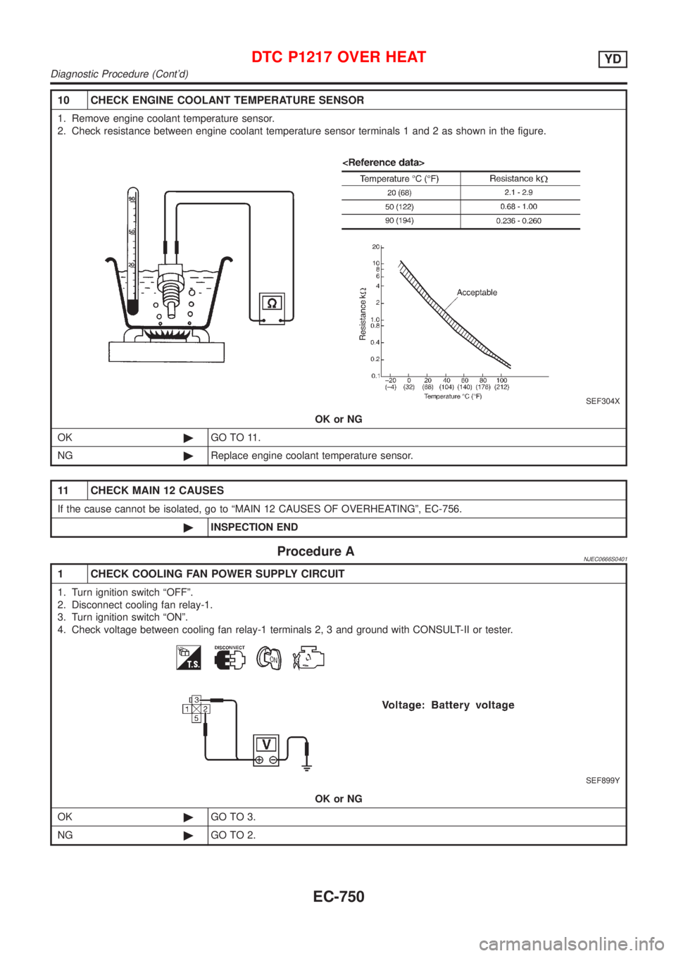
10 CHECK ENGINE COOLANT TEMPERATURE SENSOR
1. Remove engine coolant temperature sensor.
2. Check resistance between engine coolant temperature sensor terminals 1 and 2 as shown in the figure.
SEF304X
OK or NG
OK©GO TO 11.
NG©Replace engine coolant temperature sensor.
11 CHECK MAIN 12 CAUSES
If the cause cannot be isolated, go to ªMAIN 12 CAUSES OF OVERHEATINGº, EC-756.
©INSPECTION END
Procedure ANJEC0666S0401
1 CHECK COOLING FAN POWER SUPPLY CIRCUIT
1. Turn ignition switch ªOFFº.
2. Disconnect cooling fan relay-1.
3. Turn ignition switch ªONº.
4. Check voltage between cooling fan relay-1 terminals 2, 3 and ground with CONSULT-II or tester.
SEF899Y
OK or NG
OK©GO TO 3.
NG©GO TO 2.
DTC P1217 OVER HEATYD
Diagnostic Procedure (Cont'd)
EC-750
Page 1480 of 2898
9 CHECK INTERMITTENT INCIDENT
1. Perform ªTROUBLE DIAGNOSIS FOR INTERMITTENT INCIDENTº, EC-665.
©INSPECTION END
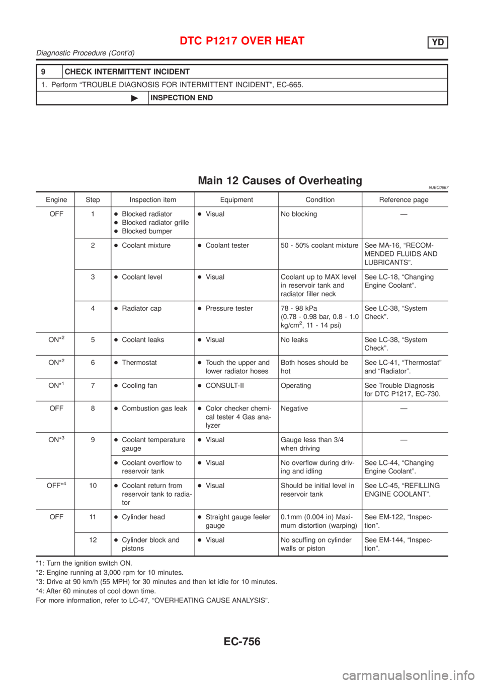
Main 12 Causes of OverheatingNJEC0667
Engine Step Inspection item Equipment Condition Reference page
OFF 1+Blocked radiator
+Blocked radiator grille
+Blocked bumper+Visual No blocking Ð
2+Coolant mixture+Coolant tester 50 - 50% coolant mixture See MA-16, ªRECOM-
MENDED FLUIDS AND
LUBRICANTSº.
3+Coolant level+Visual Coolant up to MAX level
in reservoir tank and
radiator filler neckSee LC-18, ªChanging
Engine Coolantº.
4+Radiator cap+Pressure tester 78 - 98 kPa
(0.78 - 0.98 bar, 0.8 - 1.0
kg/cm
2, 11 - 14 psi)See LC-38, ªSystem
Checkº.
ON*
25+Coolant leaks+Visual No leaks See LC-38, ªSystem
Checkº.
ON*
26+Thermostat+Touch the upper and
lower radiator hosesBoth hoses should be
hotSee LC-41, ªThermostatº
and ªRadiatorº.
ON*
17+Cooling fan+CONSULT-II Operating See Trouble Diagnosis
for DTC P1217, EC-730.
OFF 8+Combustion gas leak+Color checker chemi-
cal tester 4 Gas ana-
lyzerNegative Ð
ON*
39+Coolant temperature
gauge+Visual Gauge less than 3/4
when drivingÐ
+Coolant overflow to
reservoir tank+Visual No overflow during driv-
ing and idlingSee LC-44, ªChanging
Engine Coolantº.
OFF*
410+Coolant return from
reservoir tank to radia-
tor+Visual Should be initial level in
reservoir tankSee LC-45, ªREFILLING
ENGINE COOLANTº.
OFF 11+Cylinder head+Straight gauge feeler
gauge0.1mm (0.004 in) Maxi-
mum distortion (warping)See EM-122, ªInspec-
tionº.
12+Cylinder block and
pistons+Visual No scuffing on cylinder
walls or pistonSee EM-144, ªInspec-
tionº.
*1: Turn the ignition switch ON.
*2: Engine running at 3,000 rpm for 10 minutes.
*3: Drive at 90 km/h (55 MPH) for 30 minutes and then let idle for 10 minutes.
*4: After 60 minutes of cool down time.
For more information, refer to LC-47, ªOVERHEATING CAUSE ANALYSISº.
DTC P1217 OVER HEATYD
Diagnostic Procedure (Cont'd)
EC-756
Page 1530 of 2898
DescriptionNJEC0760SYSTEM DESCRIPTIONNJEC0760S01
Sensor Input Signal to ECMECM
Func-
tionActuator
Crankshaft position sensor
(TDC)Engine speed
Glow
controlGlow lamp,
Glow relay
¯
Glow plugs Engine coolant tempera-
ture sensorEngine coolant tem-
perature
When engine coolant temperature is more than approximately
75ÉC (167ÉF), the glow relay turns off.
When coolant temperature is lower than approximately 75ÉC
(167ÉF):
+Ignition switch ON
After ignition switch has turned to ON, the glow relay turns ON
for a certain period of time in relation to engine coolant
temperature, allowing current to flow through glow plug.
+Cranking
The glow relay turns ON, allowing current to flow through glow
plug.
+Starting
After engine has started, current continues to flow through
glow plug (after-glow mode) for a certain period in relation to
engine coolant temperature.
The glow indicator lamp turns ON for a certain period of time in
relation to engine cooalnt temperature at the time glow relay is
turned ON.
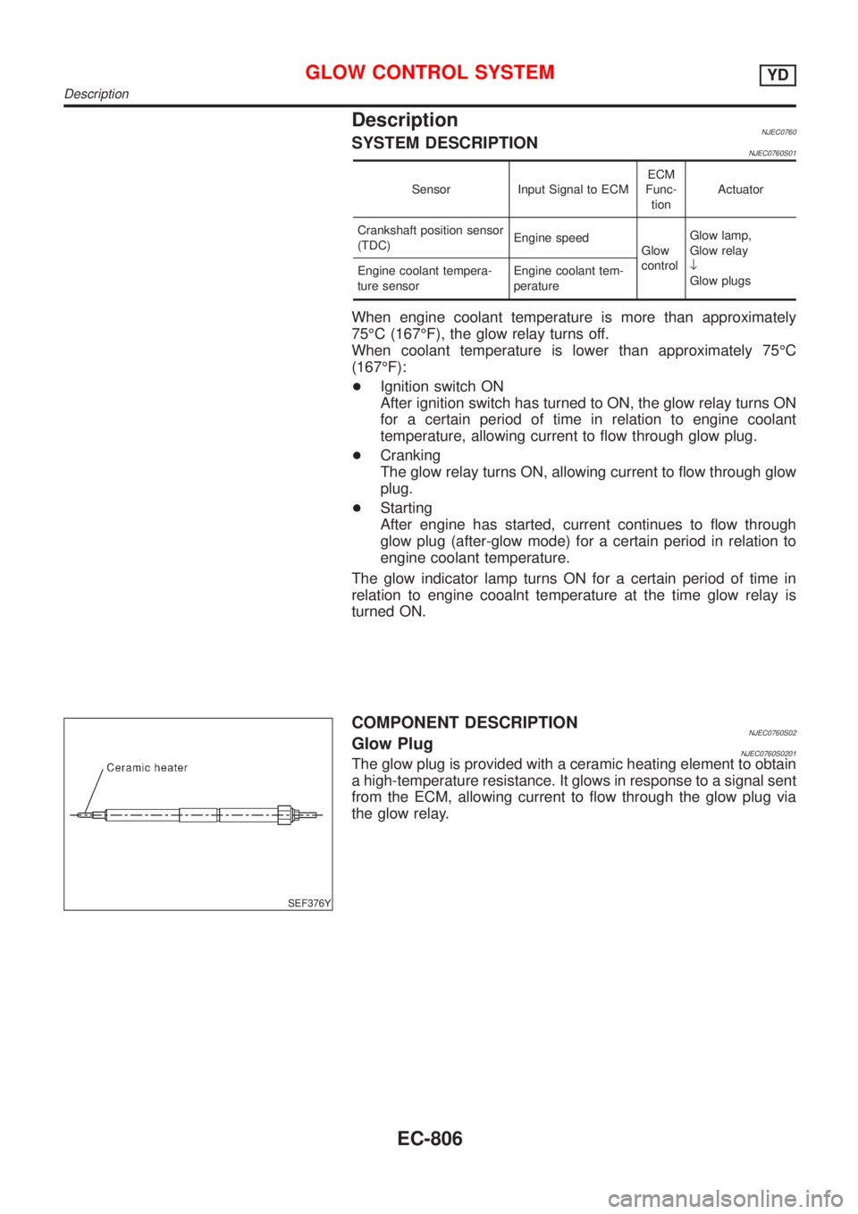
SEF376Y
COMPONENT DESCRIPTIONNJEC0760S02Glow PlugNJEC0760S0201The glow plug is provided with a ceramic heating element to obtain
a high-temperature resistance. It glows in response to a signal sent
from the ECM, allowing current to flow through the glow plug via
the glow relay.
GLOW CONTROL SYSTEMYD
Description
EC-806
Page 1537 of 2898
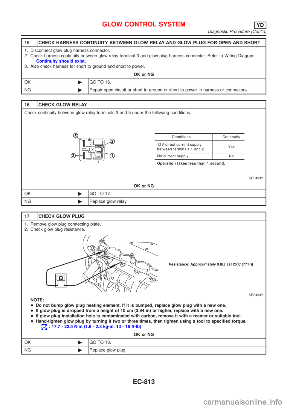
15 CHECK HARNESS CONTINUITY BETWEEN GLOW RELAY AND GLOW PLUG FOR OPEN AND SHORT
1. Disconnect glow plug harness connector.
2. Check harness continuity between glow relay terminal 3 and glow plug harness connector. Refer to Wiring Diagram.
Continuity should exist.
3. Also check harness for short to ground and short to power.
OK or NG
OK©GO TO 16.
NG©Repair open circuit or short to ground or short to power in harness or connectors.
16 CHECK GLOW RELAY
Check continuity between glow relay terminals 3 and 5 under the following conditions.
SEF433Y
OK or NG
OK©GO TO 17.
NG©Replace glow relay.
17 CHECK GLOW PLUG
1. Remove glow plug connecting plate.
2. Check glow plug resistance.
SEF434Y
NOTE:
+Do not bump glow plug heating element. If it is bumped, replace glow plug with a new one.
+If glow plug is dropped from a height of 10 cm (3.94 in) or higher, replace with a new one.
+If glow plug installation hole is contaminated with carbon, remove it with a reamer or suitable tool.
+Hand-tighten glow plug by turning it two or three times, then tighten using a tool to specified torque.
: 17.7 - 22.5 N´m (1.8 - 2.3 kg-m, 13 - 16 ft-lb)
OK or NG
OK©GO TO 18.
NG©Replace glow plug.
GLOW CONTROL SYSTEMYD
Diagnostic Procedure (Cont'd)
EC-813
Page 2354 of 2898
+Do not use gasoline, kerosine, diesel fuel, gas oil, thinners or
solvents for cleaning skin.
+If skin disorders develop, obtain medical advice without delay.
+Where practicable, degrease components prior to handling.
+Where there is a risk of eye contact, eye protection should be
worn, for example, chemical goggles or face shields; in addi-
tion an eye wash facility should be provided.
Environmental Protection PrecautionsNJGI0001S0702Burning used engine oil in small space heaters or boilers can be
recommended only for units of approved design. The heating sys-
tem must meet the requirements of HM Inspectorate of Pollution for
small burners of less than 0.4 MW. If in doubt, check with the
appropriate local authority and/or manufacturer of the approved
appliance.
Dispose of used oil and used oil filters through authorized waste
disposal contractors to licensed waste disposal sites, or to the
waste oil reclamation trade. If in doubt, contact the local authority
for advice on disposal facilities.
It is illegal to pour used oil on to the ground, down sewers or drains,
or into water courses.
The regulations concerning the pollution vary between
regions.
PRECAUTIONS FOR FUELNJGI0001S08Gasoline EngineNJGI0001S0803Models with three way catalyst
Unleaded premium gasoline of at least 95 octane (RON)
If premium gasoline is not available, unleaded regular gaso-
line with an octane rating of 91 (RON) may be temporarily
used, but only under the following precautions:
+Have the fuel tank filled only partially with unleaded regu-
lar gasoline, and fill up with premium unleaded gasoline
as soon as possible.
+Avoid full throttle driving and abrupt acceleration.
CAUTION:
Do not use leaded gasoline. Using leaded gasoline will dam-
age the three way catalyst.
Diesel Engine*:NJGI0001S0804Diesel fuel of at least 50 cetane
* If two types of diesel fuel are available, use summer or winter
fuel properly according to the following temperature conditions.
+Above þ7ÉC (20ÉF) ... Summer type diesel fuel.
+Below þ7ÉC (20ÉF) ... Winter type diesel fuel.
CAUTION:
+Do not use home heating oil, gasoline, or other alternate
fuels in your diesel engine. The use of those can cause
engine damage.
+Do not use summer fuel at temperatures below þ7ÉC
(20ÉF). The cold temperatures will cause wax to form in the
fuel. As a result, it may prevent the engine from running
smoothly.
+Do not add gasoline or other alternate fuels to diesel fuel.
PRECAUTIONS FOR AIR CONDITIONINGNJGI0001S09Use an approved refrigerant recovery unit any time the air condi-
tioning system must be discharged. Refer to HA-78, ªHFC-134a
(R-134a) Service Procedureº for specific instructions.
PRECAUTIONS
Precautions (Cont'd)
GI-8
Page 2369 of 2898
Engine Compartment
There are several reasons a vehicle or engine vibration could
cause an electrical complaint. Some of the things to check for are:
+Connectors not fully seated.
+Wiring harness not long enough and is being stressed due to
engine vibrations or rocking.
+Wires laying across brackets or moving components.
+Loose, dirty or corroded ground wires.
+Wires routed too close to hot components.
To inspect components under the hood, start by verifying the integ-
rity of ground connections. (Refer to GROUND INSPECTION
described later.) First check that the system is properly grounded.
Then check for loose connection bygently shakingthe wiring or
components as previously explained. Using the wiring diagrams
inspect the wiring for continuity.
Behind The Instrument Panel
An improperly routed or improperly clamped harness can become
pinched during accessory installation. Vehicle vibration can aggra-
vate a harness which is routed along a bracket or near a screw.
Under Seating Areas
An unclamped or loose harness can cause wiring to be pinched by
seat components (such as slide guides) during vehicle vibration. If
the wiring runs under seating areas, inspect wire routing for pos-
sible damage or pinching.
SGI842
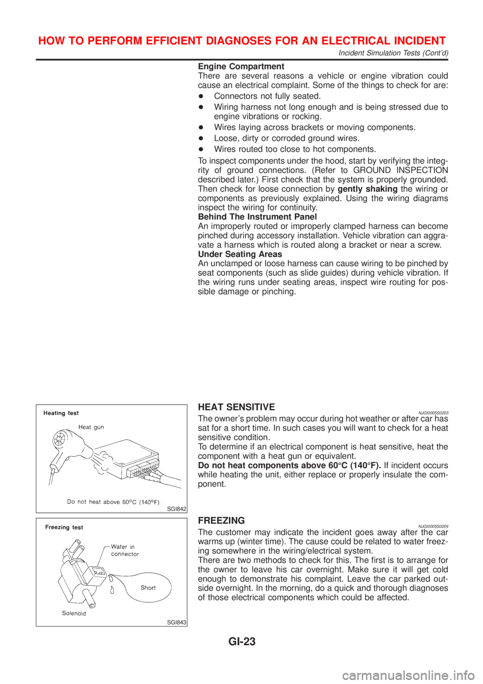
HEAT SENSITIVENJGI0005S0203The owner's problem may occur during hot weather or after car has
sat for a short time. In such cases you will want to check for a heat
sensitive condition.
To determine if an electrical component is heat sensitive, heat the
component with a heat gun or equivalent.
Do not heat components above 60ÉC (140ÉF).If incident occurs
while heating the unit, either replace or properly insulate the com-
ponent.
SGI843
FREEZINGNJGI0005S0204The customer may indicate the incident goes away after the car
warms up (winter time). The cause could be related to water freez-
ing somewhere in the wiring/electrical system.
There are two methods to check for this. The first is to arrange for
the owner to leave his car overnight. Make sure it will get cold
enough to demonstrate his complaint. Leave the car parked out-
side overnight. In the morning, do a quick and thorough diagnoses
of those electrical components which could be affected.
HOW TO PERFORM EFFICIENT DIAGNOSES FOR AN ELECTRICAL INCIDENT
Incident Simulation Tests (Cont'd)
GI-23