2001 NISSAN ALMERA seat adjustment
[x] Cancel search: seat adjustmentPage 450 of 2898
NAT033
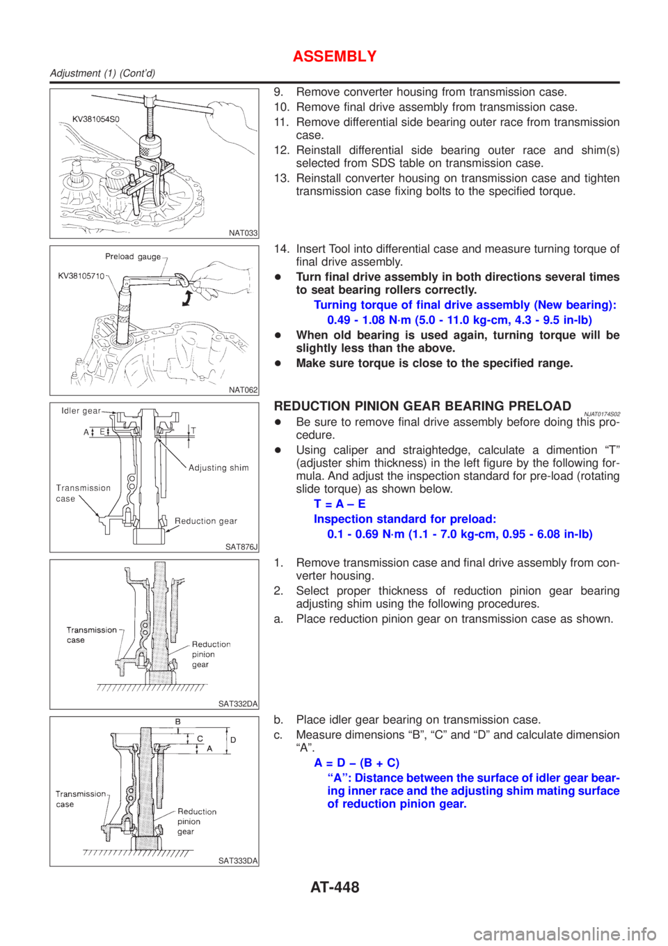
9. Remove converter housing from transmission case.
10. Remove final drive assembly from transmission case.
11. Remove differential side bearing outer race from transmission
case.
12. Reinstall differential side bearing outer race and shim(s)
selected from SDS table on transmission case.
13. Reinstall converter housing on transmission case and tighten
transmission case fixing bolts to the specified torque.
NAT062
14. Insert Tool into differential case and measure turning torque of
final drive assembly.
+Turn final drive assembly in both directions several times
to seat bearing rollers correctly.
Turning torque of final drive assembly (New bearing):
0.49 - 1.08 N´m (5.0 - 11.0 kg-cm, 4.3 - 9.5 in-lb)
+When old bearing is used again, turning torque will be
slightly less than the above.
+Make sure torque is close to the specified range.
SAT876J
REDUCTION PINION GEAR BEARING PRELOADNJAT0174S02+Be sure to remove final drive assembly before doing this pro-
cedure.
+Using caliper and straightedge, calculate a dimention ªTº
(adjuster shim thickness) in the left figure by the following for-
mula. And adjust the inspection standard for pre-load (rotating
slide torque) as shown below.
T=A±E
Inspection standard for preload:
0.1 - 0.69 N´m (1.1 - 7.0 kg-cm, 0.95 - 6.08 in-lb)
SAT332DA
1. Remove transmission case and final drive assembly from con-
verter housing.
2. Select proper thickness of reduction pinion gear bearing
adjusting shim using the following procedures.
a. Place reduction pinion gear on transmission case as shown.
SAT333DA
b. Place idler gear bearing on transmission case.
c. Measure dimensions ªBº, ªCº and ªDº and calculate dimension
ªAº.
A=Dþ(B+C)
ªAº: Distance between the surface of idler gear bear-
ing inner race and the adjusting shim mating surface
of reduction pinion gear.
ASSEMBLY
Adjustment (1) (Cont'd)
AT-448
Page 452 of 2898
SAT338DA
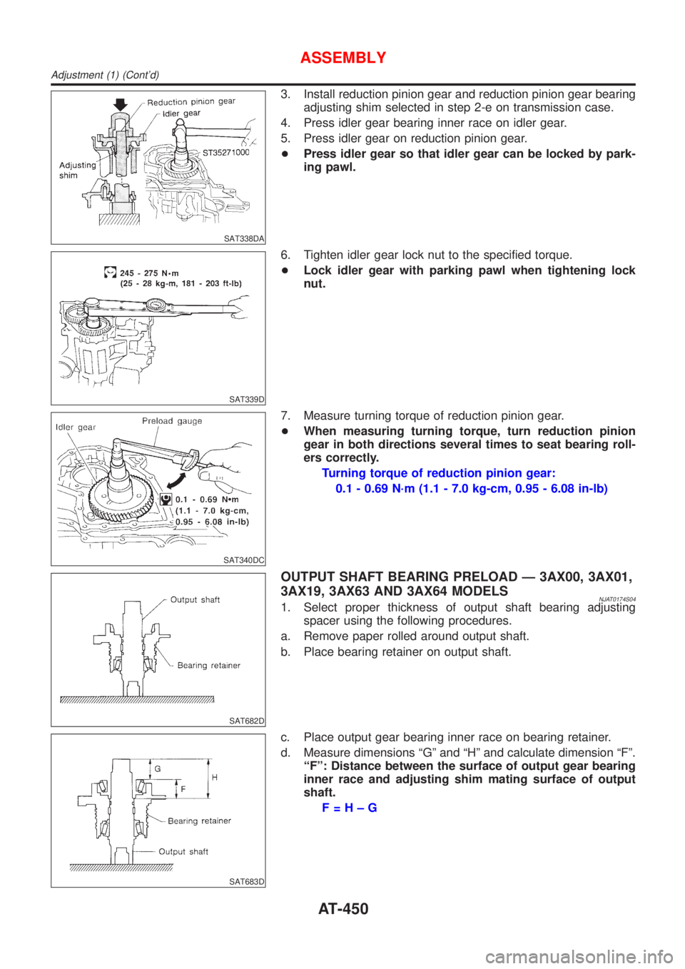
3. Install reduction pinion gear and reduction pinion gear bearing
adjusting shim selected in step 2-e on transmission case.
4. Press idler gear bearing inner race on idler gear.
5. Press idler gear on reduction pinion gear.
+Press idler gear so that idler gear can be locked by park-
ing pawl.
SAT339D
6. Tighten idler gear lock nut to the specified torque.
+Lock idler gear with parking pawl when tightening lock
nut.
SAT340DC
7. Measure turning torque of reduction pinion gear.
+When measuring turning torque, turn reduction pinion
gear in both directions several times to seat bearing roll-
ers correctly.
Turning torque of reduction pinion gear:
0.1 - 0.69 N´m (1.1 - 7.0 kg-cm, 0.95 - 6.08 in-lb)
SAT682D
OUTPUT SHAFT BEARING PRELOAD Ð 3AX00, 3AX01,
3AX19, 3AX63 AND 3AX64 MODELS
NJAT0174S041. Select proper thickness of output shaft bearing adjusting
spacer using the following procedures.
a. Remove paper rolled around output shaft.
b. Place bearing retainer on output shaft.
SAT683D
c. Place output gear bearing inner race on bearing retainer.
d. Measure dimensions ªGº and ªHº and calculate dimension ªFº.
ªFº: Distance between the surface of output gear bearing
inner race and adjusting shim mating surface of output
shaft.
F=H±G
ASSEMBLY
Adjustment (1) (Cont'd)
AT-450
Page 454 of 2898

SAT688D
3. Place output shaft on bearing retainer.
4. Place output shaft bearing adjusting spacer selected in step
1-g on output shaft.
5. Press output gear bearing inner race on output gear.
6. Press output gear on output shaft.
SAT689D
7. Tighten output gear lock nut to specified torque.
SAT690D
8. Remove idler gear to measure output shaft bearing preload.
SAT691D
9. Measure output shaft bearing preload.
+When measuring bearing preload, turn output shaft in
both directions several times to seat bearing rollers cor-
rectly.
Output shaft bearing preload:
0.25 - 0.88 N´m (2.5 - 9.0 kg-cm, 2.2 - 7.8 in-lb)
+If not within specified range, readjust bearing preload.
SAT692D
10. Install idler gear and tighten lock nut to specified torque.
11. After properly adjusting bearing preload, clinch idler gear and
output gear lock nuts as shown.
ASSEMBLY
Adjustment (1) (Cont'd)
AT-452
Page 517 of 2898
BRAKE SYSTEM
SECTION
BR
CONTENTS
PRECAUTIONS...............................................................4
Supplemental Restraint System (SRS)²AIR
BAG²and²SEAT BELT PRE-TENSIONER²...............4
Precautions for Brake System .....................................4
Precautions When Working On ABS ...........................5
Wiring Diagrams and Trouble Diagnosis .....................5
PREPARATION...............................................................6
Commercial Service Tools ...........................................6
NOISE, VIBRATION AND HARSHNESS (NVH)
TROUBLESHOOTING.....................................................7
NVH Troubleshooting Chart.........................................7
ON-VEHICLE SERVICE..................................................8
Checking Brake Fluid Level.........................................8
Checking Brake Line ...................................................8
Changing Brake Fluid ..................................................8
Brake Burnishing Procedure........................................8
Bleeding Brake System ...............................................9
BRAKE HYDRAULIC LINE...........................................10
Hydraulic Circuit.........................................................10
Removal .....................................................................10
Inspection................................................................... 11
Installation .................................................................. 11
BRAKE PEDAL AND BRACKET..................................12
Removal and Installation ...........................................12
Inspection...................................................................12
Adjustment .................................................................12
MASTER CYLINDER (TOKICO)...................................14
Removal .....................................................................14
Disassembly...............................................................15
Inspection...................................................................15
Assembly ...................................................................15
Installation ..................................................................16
MASTER CYLINDER [BOSCH (NABCO)]...................17
Removal .....................................................................17
Disassembly...............................................................17
Inspection...................................................................18
Assembly ...................................................................18
Installation ..................................................................19BRAKE BOOSTER........................................................20
On-vehicle Service.....................................................20
OPERATING CHECK...............................................20
AIRTIGHT CHECK...................................................20
Removal .....................................................................20
Inspection...................................................................20
OUTPUT ROD LENGTH CHECK..............................20
Installation ..................................................................21
VACUUM HOSE.............................................................22
Removal and Installation ...........................................22
Inspection...................................................................22
HOSES AND CONNECTORS...................................22
CHECK VALVE........................................................22
VACUUM PUMP............................................................23
Removal .....................................................................23
Installation ..................................................................24
Inspection...................................................................24
Component ................................................................25
Disassembly...............................................................25
Assembly ...................................................................25
FRONT DISC BRAKE...................................................27
Component ................................................................27
Pad Replacement ......................................................27
Removal .....................................................................28
Disassembly...............................................................28
Inspection...................................................................28
CALIPER.................................................................28
ROTOR...................................................................29
Assembly ...................................................................30
Installation ..................................................................30
REAR DRUM BRAKE...................................................31
Components...............................................................31
Removal .....................................................................31
Inspection - Wheel Cylinder ......................................32
Wheel Cylinder Overhaul...........................................33
Inspection - Drum ......................................................33
Inspection - Lining .....................................................33
Installation ..................................................................33
Page 619 of 2898
BODY & TRIM
SECTION
BT
CONTENTS
PRECAUTIONS...............................................................3
Service Notice..............................................................3
Supplemental Restraint System (SRS)²AIR
BAG²and²SEAT BELT PRE-TENSIONER²...............3
CLIP AND FASTENER....................................................4
Description ...................................................................4
CHASSIS AND BODY MAINTENANCE (FOR
EUROPE).........................................................................6
Checking Body Corrosion ............................................6
BODY FRONT END.........................................................7
Removal and Installation .............................................7
FRONT BUMPER ASSEMBLY....................................7
BODY REAR END AND OPENER................................10
Removal and Installation (Sedan) .............................10
REAR BUMPER ASSEMBLY....................................10
Removal and Installation (Hatchback).......................13
REAR BUMPER ASSEMBLY....................................13
DOOR.............................................................................16
Adjustment .................................................................16
STRIKER ADJUSTMENT..........................................16
Front Door Glass .......................................................17
FRONT DOOR GLASS AND REGULATOR................17
Rear Door Glass ........................................................18
REAR DOOR GLASS AND REGULATOR..................19
Front Door Lock .........................................................21
BELL CRANK ADJUSTMENT....................................21
OUTSIDE HANDLE ROD ADJUSTMENT...................21
REMOVAL...............................................................22
Rear Door Lock .........................................................23
OUTSIDE HANDLE ROD ADJUSTMENT...................23
REMOVAL...............................................................24
INSTRUMENT PANEL ASSEMBLY.............................25
Removal and Installation ...........................................25
SIDE AND FLOOR TRIM...............................................31
Removal and Installation ...........................................31
SEDAN...................................................................31
3-DOOR HATCHBACK.............................................34
5-DOOR HATCHBACK.............................................36
DOOR TRIM...................................................................39
Removal and Installation ...........................................39ROOF TRIM...................................................................43
Removal and Installation ...........................................43
TRUNK ROOM TRIM.....................................................45
Removal and Installation ...........................................45
SEDAN...................................................................45
BACK DOOR TRIM.......................................................46
Removal and Installation ...........................................46
3-DOOR AND 5-DOOR HATCHBACK.......................46
EXTERIOR.....................................................................47
Removal and Installation ...........................................47
FRONT SEAT................................................................56
Removal and Installation ...........................................56
MANUAL SEAT (SEDAN).........................................57
MANUAL SEAT (HATCHBACK)................................58
Heated Seat ...............................................................59
Active Head Restraint ................................................59
OPERATION OUTLINE............................................59
REAR SEAT...................................................................60
Removal and Installation ...........................................60
SEDAN...................................................................60
SEDAN (FOR EUROPE)...........................................61
HATCHBACK...........................................................62
SUNROOF......................................................................63
Adjustment .................................................................63
Removal .....................................................................63
Trouble Diagnoses.....................................................67
DIAGNOSTIC TABLE................................................67
WIND DEFLECTOR.................................................67
ADJUSTMENT.........................................................68
DRAIN HOSES........................................................69
WEATHERSTRIP.....................................................69
LINK AND WIRE ASSEMBLY....................................70
WINDSHIELD AND WINDOWS....................................71
Removal and Installation ...........................................71
REMOVAL...............................................................71
INSTALLATION........................................................71
WINDSHIELD..........................................................72
SIDE WINDOW........................................................73
BACK DOOR WINDOW............................................74
DOOR MIRROR.............................................................75
Page 709 of 2898
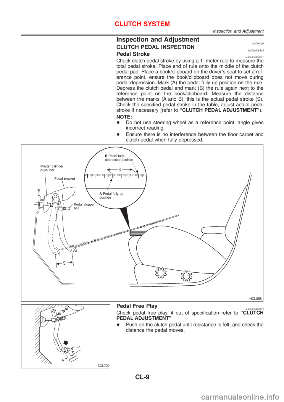
Inspection and AdjustmentNJCL0006CLUTCH PEDAL INSPECTIONNJCL0006S03Pedal StrokeNJCL0006S0301Check clutch pedal stroke by using a 1±meter rule to measure the
total pedal stroke. Place end of rule onto the middle of the clutch
pedal pad. Place a book/clipboard on the driver's seat to set a ref-
erence point, ensure the book/clipboard does not move during
pedal depression. Mark (A) the pedal fully up position on the rule.
Depress the clutch pedal and mark (B) the rule again next to the
reference point on the book/clipboard. Measure the distance
between the marks (A and B), this is the actual pedal stroke (S).
Check the specified pedal stroke in the table, adjust actual pedal
stroke if necessary (refer toªCLUTCH PEDAL ADJUSTMENTº).
NOTE:
+Do not use steering wheel as a reference point, angle gives
incorrect reading.
+Ensure there is no interference between the floor carpet and
clutch pedal when fully depressed.
NCL058
SCL702
Pedal Free PlayNJCL0006S0302Check pedal free play, if out of specification refer toªCLUTCH
PEDAL ADJUSTMENTº
+Push on the clutch pedal until resistance is felt, and check the
distance the pedal moves.
CLUTCH SYSTEM
Inspection and Adjustment
CL-9
Page 1559 of 2898
ELECTRICAL SYSTEM
SECTION
EL
CONTENTS
PRECAUTIONS...............................................................5
Supplemental Restraint System (SRS)²AIR
BAG²and²SEAT BELT PRE-TENSIONER²...............5
Wiring Diagrams and Trouble Diagnosis .....................5
HARNESS CONNECTOR................................................6
Description ...................................................................6
STANDARDIZED RELAY................................................8
Description ...................................................................8
POWER SUPPLY ROUTING.........................................10
Schematic/Sedan .......................................................10
Wiring Diagram - POWER -/Sedan With
Gasoline Engine ........................................................ 11
Wiring Diagram - POWER -/Sedan With Diesel
Engine ........................................................................19
Schematic/Hatchback ................................................26
Wiring Diagram - POWER -/Hatchback ....................28
Inspection...................................................................38
GROUND........................................................................39
Ground Distribution ....................................................39
COMBINATION SWITCH..............................................56
Check/Sedan .............................................................56
Check/Hatchback .......................................................57
Replacement ..............................................................58
STEERING SWITCH......................................................59
Check .........................................................................59
HEADLAMP...................................................................60
Wiring Diagram - H/LAMP -/Hatchback.....................60
Wiring Diagram - H/LAMP -/Sedan ...........................61
Trouble Diagnoses.....................................................63
Bulb Replacement .....................................................64
Aiming Adjustment .....................................................65
HEADLAMP - DAYTIME LIGHT SYSTEM -.................67
System Description ....................................................67
Schematic/Sedan .......................................................68
Wiring Diagram - DTRL -/Sedan ...............................69
Schematic/Hatchback ................................................72
Wiring Diagram - DTRL -/Hatchback .........................73
Trouble Diagnoses.....................................................76
Bulb Replacement .....................................................76Aiming Adjustment .....................................................77
HEADLAMP - HEADLAMP AIMING CONTROL -........78
Wiring Diagram - H/AIM -/Sedan...............................78
Wiring Diagram - H/AIM -/Hatchback ........................79
PARKING, LICENSE AND TAIL LAMPS.....................81
Wiring Diagram - TAIL/L -/Sedan ..............................81
Wiring Diagram - TAIL/L -/Hatchback ........................83
STOP LAMP..................................................................85
Wiring Diagram - STOP/L -/Sedan ............................85
Wiring Diagram - STOP/L -/Hatchback .....................86
BACK-UP LAMP............................................................87
Wiring Diagram - BACK/L -/Sedan ............................87
Wiring Diagram - BACK/L -/Hatchback .....................88
FRONT FOG LAMP.......................................................89
Wiring Diagram - F/FOG -/Sedan..............................89
Wiring Diagram - F/FOG -/Hatchback .......................90
Bulb Replacement .....................................................91
Aiming Adjustment .....................................................92
REAR FOG LAMP.........................................................93
Wiring Diagram - R/FOG -/Sedan .............................93
Wiring Diagram - R/FOG -/Hatchback.......................95
TURN SIGNAL AND HAZARD WARNING LAMPS.....96
System Description/Sedan ........................................96
Schematic/Sedan .......................................................98
Wiring Diagram - TURN -/Sedan...............................99
Trouble Diagnoses/Sedan .......................................101
Electrical Components Inspection ...........................101
System Description/Hatchback ................................102
Wiring Diagram - TURN -/Hatchback ......................103
Trouble Diagnoses/Hatchback.................................107
ILLUMINATION............................................................108
Schematic/Sedan .....................................................108
Wiring Diagram - ILL -/Sedan ..................................109
Schematic/Hatchback .............................................. 111
Wiring Diagram - ILL -/Hatchback ........................... 112
INTERIOR ROOM LAMP............................................. 115
System Description/Sedan With Interior Room
Lamp Timer .............................................................. 115
Page 1561 of 2898
Filament Repair .......................................................257
AUDIO..........................................................................258
System Description/Sedan ......................................258
Schematic/Sedan .....................................................260
Wiring Diagram - AUDIO -/Sedan ...........................261
System Description/Hatchback ................................269
Schematic/Hatchback ..............................................271
Wiring Diagram - AUDIO -/Hatchback .....................272
Trouble Diagnoses...................................................280
Inspection.................................................................281
AUDIO ANTENNA.......................................................282
Wiring Diagram - P/ANT - .......................................282
Location of Antenna/Power Antenna .......................283
Antenna Rod Replacement/Power Antenna ............284
Window Antenna Repair ..........................................284
Location of Antenna/Sedan With Manual Antenna..286
Antenna Rod Replacement/Sedan With Manual
Antenna....................................................................286
Location of Antenna/Hatchback ...............................287
Antenna Rod Replacement/Hatchback ...................287
HEATED SEAT............................................................288
Wiring Diagram - H/SEAT -/Sedan ..........................288
Wiring Diagram - H/SEAT -/Hatchback ...................290
POWER SUNROOF.....................................................292
Wiring Diagram - SROOF - .....................................292
Trouble Diagnoses...................................................293
DOOR MIRROR...........................................................294
Wiring Diagram - MIRROR -/Sedan ........................294
Wiring Diagram - MIRROR -/Hatchback .................295
TRUNK LID OPENER..................................................297
Wiring Diagram - TLID - ..........................................297
POWER WINDOW.......................................................298
System Description/Sedan ......................................298
Schematic/Sedan .....................................................300
Wiring Diagram - WINDOW -/Sedan .......................301
Trouble Diagnoses/Sedan .......................................305
System Description/Hatchback ................................306
Schematic/Hatchback ..............................................308
Wiring Diagram - WINDOW -/Hatchback ................309
Trouble Diagnoses/Hatchback.................................313
POWER DOOR LOCK.................................................314
System Description/Hatchback ................................314
Schematic/Hatchback ..............................................316
Wiring Diagram - D/LOCK -/Hatchback...................318
Trouble Diagnoses/Hatchback.................................325
System Description/Sedan ......................................333
Schematic/Sedan .....................................................334
Wiring Diagram - D/LOCK -/Sedan .........................335
Trouble Diagnoses/Sedan .......................................340
POWER DOOR LOCK - SUPER LOCK -...................349
System Description ..................................................349
Schematic/Sedan .....................................................351Wiring Diagram - S/LOCK -/Sedan .........................352
Trouble Diagnoses/Sedan .......................................358
Schematic/Hatchback ..............................................370
Wiring Diagram - S/LOCK -/Hatchback ...................372
Trouble Diagnoses/Hatchback.................................379
MULTI-REMOTE CONTROL SYSTEM.......................392
System Description/Sedan ......................................392
Wiring Diagram - MULTI -/Sedan ............................393
Trouble Diagnoses/Sedan .......................................395
ID Code Entry Procedure/Sedan .............................402
Remote Controller Battery Replacement/Sedan .....403
System Description/Hatchback ................................403
Wiring Diagram - MULTI -/Hatchback .....................405
Trouble Diagnoses/Hatchback.................................407
ID Code Entry Procedure/Hatchback ......................412
Remote Controller Battery
Replacement/Hatchback ..........................................413
TIME CONTROL UNIT................................................414
Description/Sedan....................................................414
Schematic/Sedan .....................................................415
Time Control Unit Inspection Table/Sedan ..............416
Description/Hatchback .............................................417
Trouble Diagnoses/Hatchback.................................418
Schematic/Hatchback ..............................................420
NATS (NISSAN ANTI-THEFT SYSTEM).....................422
Component Parts and Harness Connetor
Location ...................................................................422
System Description ..................................................423
System Composition ................................................424
Wiring Diagram - NATS -/Sedan .............................425
Wiring Diagram - NATS -/Hatchback.......................427
CONSULT-II .............................................................429
Trouble Diagnoses...................................................432
How to Replace NATS IMMU ..................................449
NAVIGATION SYSTEM...............................................450
Precautions ..............................................................450
Component Parts Location ......................................451
System Description ..................................................452
Schematic/Sedan .....................................................460
Wiring Diagram - NAVI -/Sedan ..............................461
Schematic/Hatchback ..............................................467
Wiring Diagram - NAVI -/Hatchback ........................468
Self-diagnosis Mode ................................................476
Confirmation/Adjustment Mode ...............................479
Control Panel Mode .................................................491
Guide Volume Setting ..............................................498
Anti-theft System .....................................................499
CONSULT-II .............................................................500
Trouble Diagnoses...................................................501
This Condition Is Not Abnormal...............................507
Program Loading .....................................................516
CONTENTS(Cont'd)
EL-3