Page 689 of 2898

SBF034BA
Removal and InstallationNJBT0023REMOVALNJBT0023S01After removing moldings, remove glass using piano wire or power
cutting tool and an inflatable pump bag.
WARNING:
When cutting the glass from the vehicle, always wear safety
glasses and heavy gloves to help prevent glass splinters from
entering your eyes or cutting your hands.
CAUTION:
+Be careful not to scratch the glass when removing.
+Do not set or stand the glass on its edge. Small chips may
develop into cracks.
SBT472
SBT473
INSTALLATIONNJBT0023S02+Use a genuine Nissan Urethane Adhesive Kit or equivalent
and follow the instructions furnished with it.
+While the urethane adhesive is curing, open a door win-
dow. This will prevent the glass from being forced out by
passenger compartment air pressure when a door is
closed.
+The molding must be installed securely so that it is in
position and leaves no gap.
+Inform the customer that the vehicle should remain sta-
tionary until the urethane adhesive has completely cured
(preferably 24 hours). Curing time varies with temperature
and humidity.
WARNING:
+Keep heat and open flames away as primers and adhesive
are flammable.
+The materials contained in the kit are harmful if
swallowed, and may irritate skin and eyes. Avoid contact
with the skin and eyes.
+Use in an open, well ventilated location. Avoid breathing
the vapors. They can be harmful if inhaled. If affected by
vapor inhalation, immediately move to an area with fresh
air.
+Driving the vehicle before the urethane adhesive has com-
pletely cured may affect the performance of the wind-
shield in case of an accident.
CAUTION:
+Do not use an adhesive which is past its usable term.
Shelf life of this product is limited to six months after the
date of manufacture. Carefully adhere to the expiration or
manufacture date printed on the box.
+Keep primers and adhesive in a cool, dry place. Ideally,
they should be stored in a refrigerator.
WINDSHIELD AND WINDOWS
Removal and Installation
BT-71
Page 2488 of 2898

Heater & Cooling Unit (Heater Core)
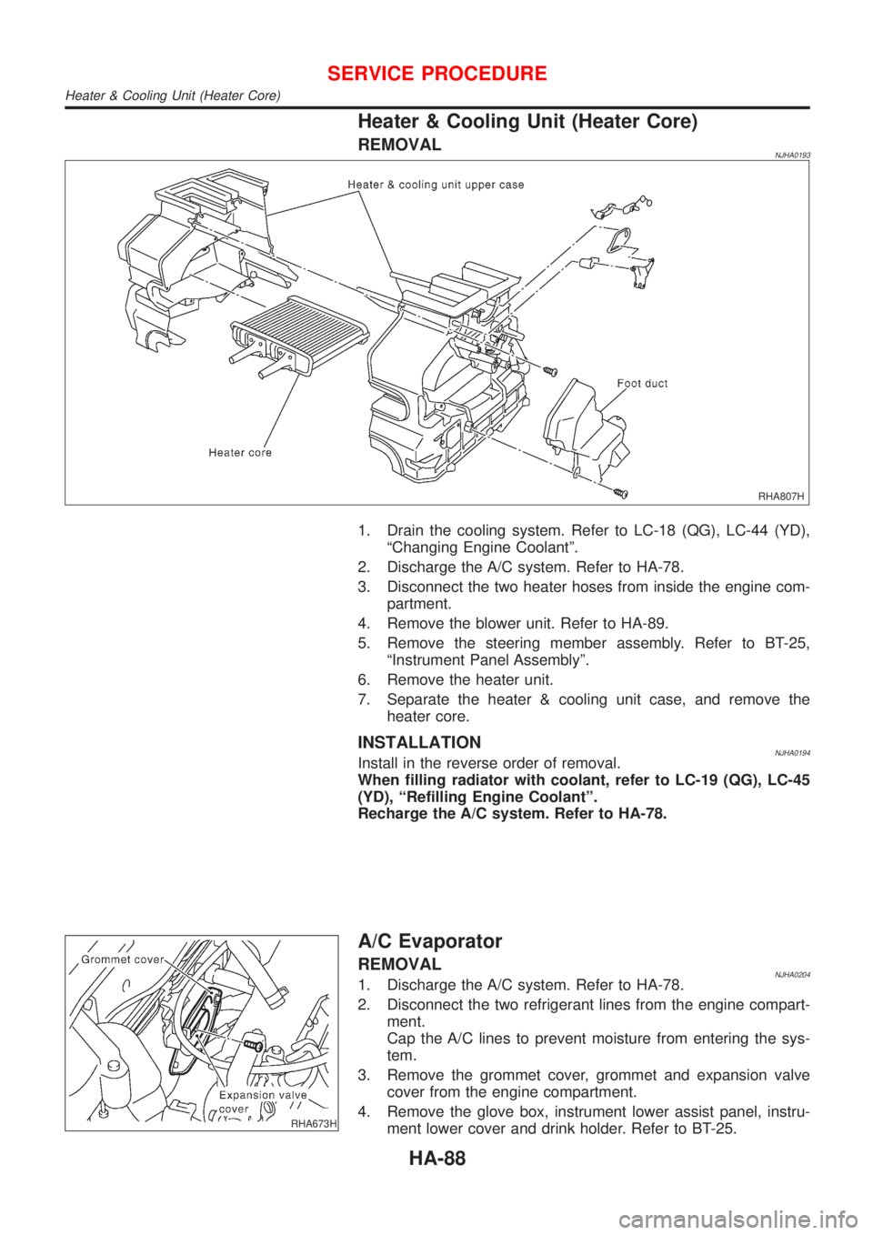
REMOVALNJHA0193
RHA807H
1. Drain the cooling system. Refer to LC-18 (QG), LC-44 (YD),
ªChanging Engine Coolantº.
2. Discharge the A/C system. Refer to HA-78.
3. Disconnect the two heater hoses from inside the engine com-
partment.
4. Remove the blower unit. Refer to HA-89.
5. Remove the steering member assembly. Refer to BT-25,
ªInstrument Panel Assemblyº.
6. Remove the heater unit.
7. Separate the heater & cooling unit case, and remove the
heater core.
INSTALLATIONNJHA0194Install in the reverse order of removal.
When filling radiator with coolant, refer to LC-19 (QG), LC-45
(YD), ªRefilling Engine Coolantº.
Recharge the A/C system. Refer to HA-78.
RHA673H
A/C Evaporator
REMOVALNJHA02041. Discharge the A/C system. Refer to HA-78.
2. Disconnect the two refrigerant lines from the engine compart-
ment.
Cap the A/C lines to prevent moisture from entering the sys-
tem.
3. Remove the grommet cover, grommet and expansion valve
cover from the engine compartment.
4. Remove the glove box, instrument lower assist panel, instru-
ment lower cover and drink holder. Refer to BT-25.
SERVICE PROCEDURE
Heater & Cooling Unit (Heater Core)
HA-88
Page 2496 of 2898
Idle Air Control Valve (IACV) Ð Auxiliary Air
Control (AAC) Valve
INSPECTIONNJHA0199+Refer to EC-376 (QG), ªSystem Descriptionº.
RHA680H
Ventilation Air Filter
FUNCTIONNJHA0171Air inside passenger compartment is kept clean at either recircula-
tion or fresh mode by installing ventilation air filter into cooling unit.
SHA868E
REPLACEMENT TIMINGNJHA0172Replace ventilation air filter.
Refer to MA-4, ªPERIODIC MAINTENANCEº.
Caution label is fixed inside the glove box.
RHA681H
REPLACEMENT PROCEDURENJHA0173+Remove glove box.
+Remove filter cover.
+Take out the ventilation air filter from blower unit.
+Replace with new one and reinstall on blower unit.
+Reinstall glove box.
SERVICE PROCEDURE
Idle Air Control Valve (IACV) Ð Auxiliary Air Control (AAC) Valve
HA-96
Page 2743 of 2898

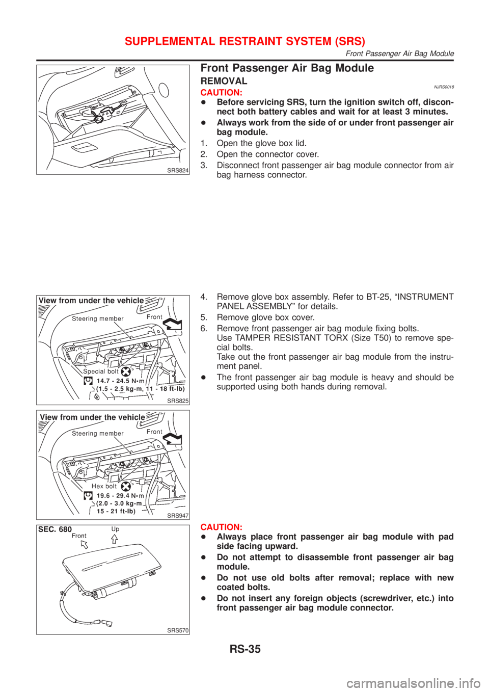
SRS824
Front Passenger Air Bag Module
REMOVALNJRS0018CAUTION:
+Before servicing SRS, turn the ignition switch off, discon-
nect both battery cables and wait for at least 3 minutes.
+Always work from the side of or under front passenger air
bag module.
1. Open the glove box lid.
2. Open the connector cover.
3. Disconnect front passenger air bag module connector from air
bag harness connector.
SRS825
SRS947
4. Remove glove box assembly. Refer to BT-25, ªINSTRUMENT
PANEL ASSEMBLYº for details.
5. Remove glove box cover.
6. Remove front passenger air bag module fixing bolts.
Use TAMPER RESISTANT TORX (Size T50) to remove spe-
cial bolts.
Take out the front passenger air bag module from the instru-
ment panel.
+The front passenger air bag module is heavy and should be
supported using both hands during removal.
SRS570
CAUTION:
+Always place front passenger air bag module with pad
side facing upward.
+Do not attempt to disassemble front passenger air bag
module.
+Do not use old bolts after removal; replace with new
coated bolts.
+Do not insert any foreign objects (screwdriver, etc.) into
front passenger air bag module connector.
SUPPLEMENTAL RESTRAINT SYSTEM (SRS)
Front Passenger Air Bag Module
RS-35
Page 2744 of 2898

SBF814E
+Replace front passenger air bag module if it has been
dropped or sustained an impact.
+Do not expose the front passenger air bag module to tem-
peratures exceeding 90ÉC (194ÉF).
+Do not allow oil, grease or water to come in contact with
the front passenger air bag module.
+After front passenger air bag inflates, the front instrument
panel assembly should be replaced if damaged.
SRS825
SRS947
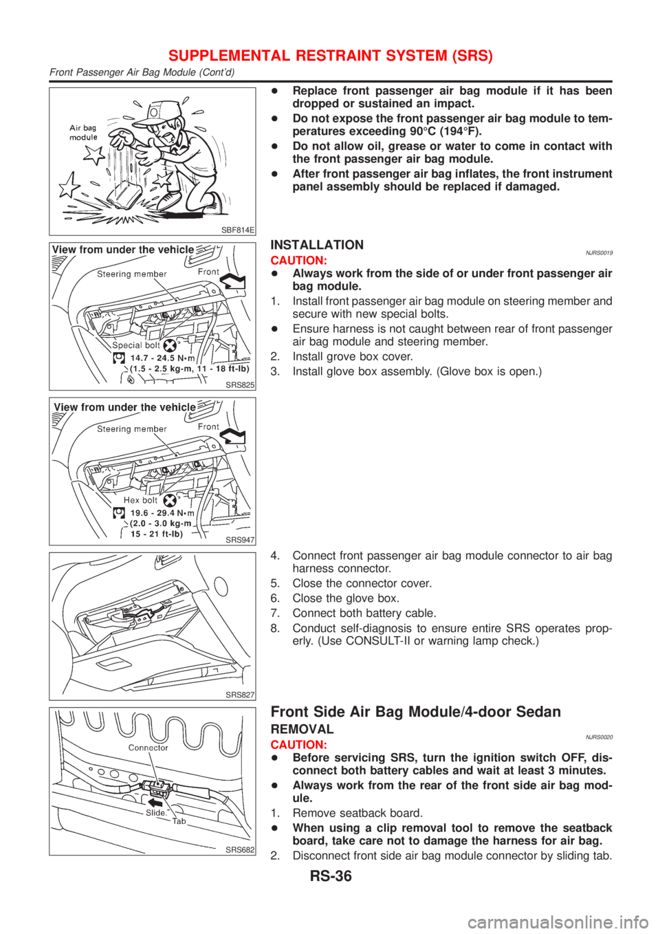
INSTALLATIONNJRS0019CAUTION:
+Always work from the side of or under front passenger air
bag module.
1. Install front passenger air bag module on steering member and
secure with new special bolts.
+Ensure harness is not caught between rear of front passenger
air bag module and steering member.
2. Install grove box cover.
3. Install glove box assembly. (Glove box is open.)
SRS827
4. Connect front passenger air bag module connector to air bag
harness connector.
5. Close the connector cover.
6. Close the glove box.
7. Connect both battery cable.
8. Conduct self-diagnosis to ensure entire SRS operates prop-
erly. (Use CONSULT-II or warning lamp check.)
SRS682
Front Side Air Bag Module/4-door Sedan
REMOVALNJRS0020CAUTION:
+Before servicing SRS, turn the ignition switch OFF, dis-
connect both battery cables and wait at least 3 minutes.
+Always work from the rear of the front side air bag mod-
ule.
1. Remove seatback board.
+When using a clip removal tool to remove the seatback
board, take care not to damage the harness for air bag.
2. Disconnect front side air bag module connector by sliding tab.
SUPPLEMENTAL RESTRAINT SYSTEM (SRS)
Front Passenger Air Bag Module (Cont'd)
RS-36