2001 NISSAN ALMERA wheel torque
[x] Cancel search: wheel torquePage 11 of 2898

parts. Apply petroleum jelly to protect O-rings and seals, or
hold bearings and washers in place during assembly. Do not
use grease.
+Extreme care should be taken to avoid damage to O-rings,
seals and gaskets when assembling.
+After overhaul, refill the transaxle with new ATF.
+When the A/T drain plug is removed, only some of the fluid is
drained. Old A/T fluid will remain in torque converter and ATF
cooling system.
Always follow the procedures under ªChanging A/T Fluidº in the
AT section when changing A/T fluid. Refer to ªChanging A/T
Fluidº, AT-15.
Service Notice or PrecautionsNJAT0247FAIL-SAFENJAT0247S01The TCM has an electronic Fail-Safe (limp home mode). This allows the vehicle to be driven even if a major
electrical input/output device circuit is damaged.
Under Fail-Safe, the vehicle always runs in third gear, even with a shift lever position of ª1º, ª2º or ªDº. The
customer may complain of sluggish or poor acceleration.
When the ignition key is turned ªONº following Fail-Safe operation, O/D OFF indicator lamp blinks for about
8 seconds. (For GENERAL AND EXCEPT FOR EURO-OBD; ªSELF-DIAGNOSTIC PROCEDURE (WITHOUT
CONSULT-II)º, refer to AT-44 and for EURO-OBD; ªTCM SELF-DIAGNOSTIC PROCEDURE (No Tools)º, refer
to AT-63.)
Fail-Safe may occur without electrical circuit damage if the vehicle is driven under extreme conditions (such
as excessive wheel spin followed by sudden braking). To recover normal shift pattern, turn the ignition key
ªOFFº for 5 seconds, then ªONº.
The blinking of the O/D OFF indicator lamp for about 8 seconds will appear only once and be cleared. The
customer may resume normal driving conditions.
Always follow the ªWORK FLOWº [Refer to AT-73 (General and except for Euro-OBD), AT-78 (EURO-OBD).]
The SELF-DIAGNOSIS results will be as follows:
The first SELF-DIAGNOSIS will indicate damage to the vehicle speed sensor or the revolution sensor.
During the next SELF-DIAGNOSIS, performed after checking the sensor, no damages will be indicated.
TORQUE CONVERTER SERVICENJAT0247S02The torque converter should be replaced under any of the following conditions:
+External leaks in the hub weld area.
+Converter hub is scored or damaged.
+Converter pilot is broken, damaged or fits poorly into crankshaft.
+Steel particles are found after flushing the cooler and cooler lines.
+Pump is damaged or steel particles are found in the converter.
+Vehicle has TCC shudder and/or no TCC apply. Replace only after all hydraulic and electrical diagnoses
have been made. (Converter clutch material may be glazed.)
+Converter is contaminated with engine coolant containing antifreeze.
+Internal failure of stator roller clutch.
+Heavy clutch debris due to overheating (blue converter).
+Steel particles or clutch lining material found in fluid filter or on magnet when no internal parts in unit are
worn or damaged Ð indicates that lining material came from converter.
PRECAUTIONS
Precautions (Cont'd)
AT-9
Page 38 of 2898
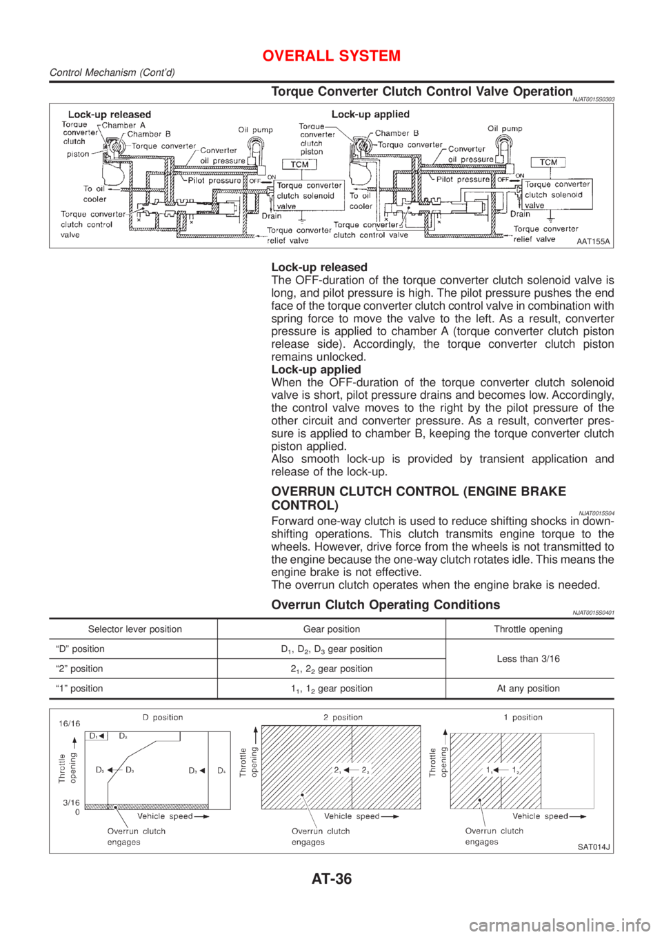
Torque Converter Clutch Control Valve OperationNJAT0015S0303
AAT155A
Lock-up released
The OFF-duration of the torque converter clutch solenoid valve is
long, and pilot pressure is high. The pilot pressure pushes the end
face of the torque converter clutch control valve in combination with
spring force to move the valve to the left. As a result, converter
pressure is applied to chamber A (torque converter clutch piston
release side). Accordingly, the torque converter clutch piston
remains unlocked.
Lock-up applied
When the OFF-duration of the torque converter clutch solenoid
valve is short, pilot pressure drains and becomes low. Accordingly,
the control valve moves to the right by the pilot pressure of the
other circuit and converter pressure. As a result, converter pres-
sure is applied to chamber B, keeping the torque converter clutch
piston applied.
Also smooth lock-up is provided by transient application and
release of the lock-up.
OVERRUN CLUTCH CONTROL (ENGINE BRAKE
CONTROL)
NJAT0015S04Forward one-way clutch is used to reduce shifting shocks in down-
shifting operations. This clutch transmits engine torque to the
wheels. However, drive force from the wheels is not transmitted to
the engine because the one-way clutch rotates idle. This means the
engine brake is not effective.
The overrun clutch operates when the engine brake is needed.
Overrun Clutch Operating ConditionsNJAT0015S0401
Selector lever position Gear position Throttle opening
ªDº position D
1,D2,D3gear position
Less than 3/16
ª2º position 2
1,22gear position
ª1º position 1
1,12gear position At any position
SAT014J
OVERALL SYSTEM
Control Mechanism (Cont'd)
AT-36
Page 357 of 2898
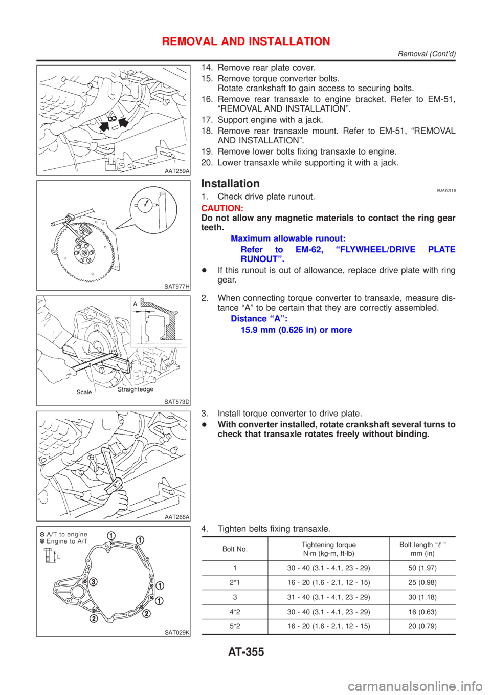
AAT259A
14. Remove rear plate cover.
15. Remove torque converter bolts.
Rotate crankshaft to gain access to securing bolts.
16. Remove rear transaxle to engine bracket. Refer to EM-51,
ªREMOVAL AND INSTALLATIONº.
17. Support engine with a jack.
18. Remove rear transaxle mount. Refer to EM-51, ªREMOVAL
AND INSTALLATIONº.
19. Remove lower bolts fixing transaxle to engine.
20. Lower transaxle while supporting it with a jack.
SAT977H
InstallationNJAT01161. Check drive plate runout.
CAUTION:
Do not allow any magnetic materials to contact the ring gear
teeth.
Maximum allowable runout:
Refer to EM-62, ªFLYWHEEL/DRIVE PLATE
RUNOUTº.
+If this runout is out of allowance, replace drive plate with ring
gear.
SAT573D
2. When connecting torque converter to transaxle, measure dis-
tance ªAº to be certain that they are correctly assembled.
Distance ªAº:
15.9 mm (0.626 in) or more
AAT266A
3. Install torque converter to drive plate.
+With converter installed, rotate crankshaft several turns to
check that transaxle rotates freely without binding.
SAT029K
4. Tighten belts fixing transaxle.
Bolt No.Tightening torque
N´m (kg-m, ft-lb)Bolt length ª!º
mm (in)
1 30 - 40 (3.1 - 4.1, 23 - 29) 50 (1.97)
2*1 16 - 20 (1.6 - 2.1, 12 - 15) 25 (0.98)
3 31 - 40 (3.1 - 4.1, 23 - 29) 30 (1.18)
4*2 30 - 40 (3.1 - 4.1, 23 - 29) 16 (0.63)
5*2 16 - 20 (1.6 - 2.1, 12 - 15) 20 (0.79)
REMOVAL AND INSTALLATION
Removal (Cont'd)
AT-355
Page 490 of 2898

SBR686C
Precautions
PRECAUTIONSNJAX0001+When installing rubber parts, final tightening must be car-
ried out under unladen condition* with tires on ground.
*: Fuel, radiator coolant and engine oil full. Spare tire, jack,
hand tools and mats in designated positions.
+After installing removed suspension parts, check wheel
alignment and adjust if necessary.
+Use flare nut wrench when removing or installing brake
tubes.
+Always torque brake lines when installing.
Preparation
SPECIAL SERVICE TOOLSNJAX0002
Tool number
Tool nameDescription
HT72520000
Ball joint remover
NT146
Removing tie-rod outer end and lower ball joint
KV38106800
Differential side oil seal
protector
NT147
Installing drive shaft
KV38106800
COMMERCIAL SERVICE TOOLSNJAX0003
Tool name Description
1 Flare nut crowfoot
2 Torque wrench
NT360
Removing and installing each brake piping
a: 10 mm (0.39 in)
FRONT AXLE
Precautions
AX-2
Page 491 of 2898
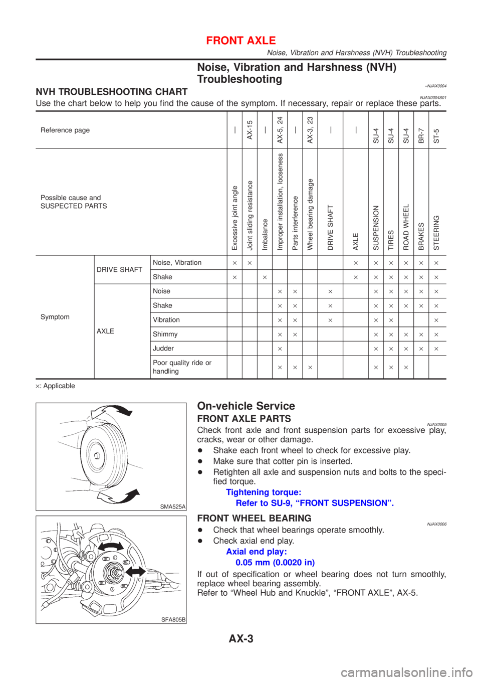
Noise, Vibration and Harshness (NVH)
Troubleshooting
=NJAX0004NVH TROUBLESHOOTING CHARTNJAX0004S01Use the chart below to help you find the cause of the symptom. If necessary, repair or replace these parts.
Reference pageÐ
AX-15
Ð
AX-5, 24
Ð
AX-3, 23
Ð
Ð
SU-4
SU-4
SU-4
BR-7
ST-5
Possible cause and
SUSPECTED PARTS
Excessive joint angle
Joint sliding resistance
Imbalance
Improper installation, looseness
Parts interference
Wheel bearing damage
DRIVE SHAFT
AXLE
SUSPENSION
TIRES
ROAD WHEEL
BRAKES
STEERING
SymptomDRIVE SHAFTNoise, Vibration´´ ´ ´´´´´
Shake´ ´ ´ ´´´´´
AXLENoise´´ ´ ´´´´´
Shake´´ ´ ´´´´´
Vibration´´ ´ ´´ ´
Shimmy´´ ´´´´´
Judder´ ´´´´´
Poor quality ride or
handling´´´ ´´´
´: Applicable
SMA525A
On-vehicle Service
FRONT AXLE PARTSNJAX0005Check front axle and front suspension parts for excessive play,
cracks, wear or other damage.
+Shake each front wheel to check for excessive play.
+Make sure that cotter pin is inserted.
+Retighten all axle and suspension nuts and bolts to the speci-
fied torque.
Tightening torque:
Refer to SU-9, ªFRONT SUSPENSIONº.
SFA805B
FRONT WHEEL BEARINGNJAX0006+Check that wheel bearings operate smoothly.
+Check axial end play.
Axial end play:
0.05 mm (0.0020 in)
If out of specification or wheel bearing does not turn smoothly,
replace wheel bearing assembly.
Refer to ªWheel Hub and Knuckleº, ªFRONT AXLEº, AX-5.
FRONT AXLE
Noise, Vibration and Harshness (NVH) Troubleshooting
AX-3
Page 509 of 2898
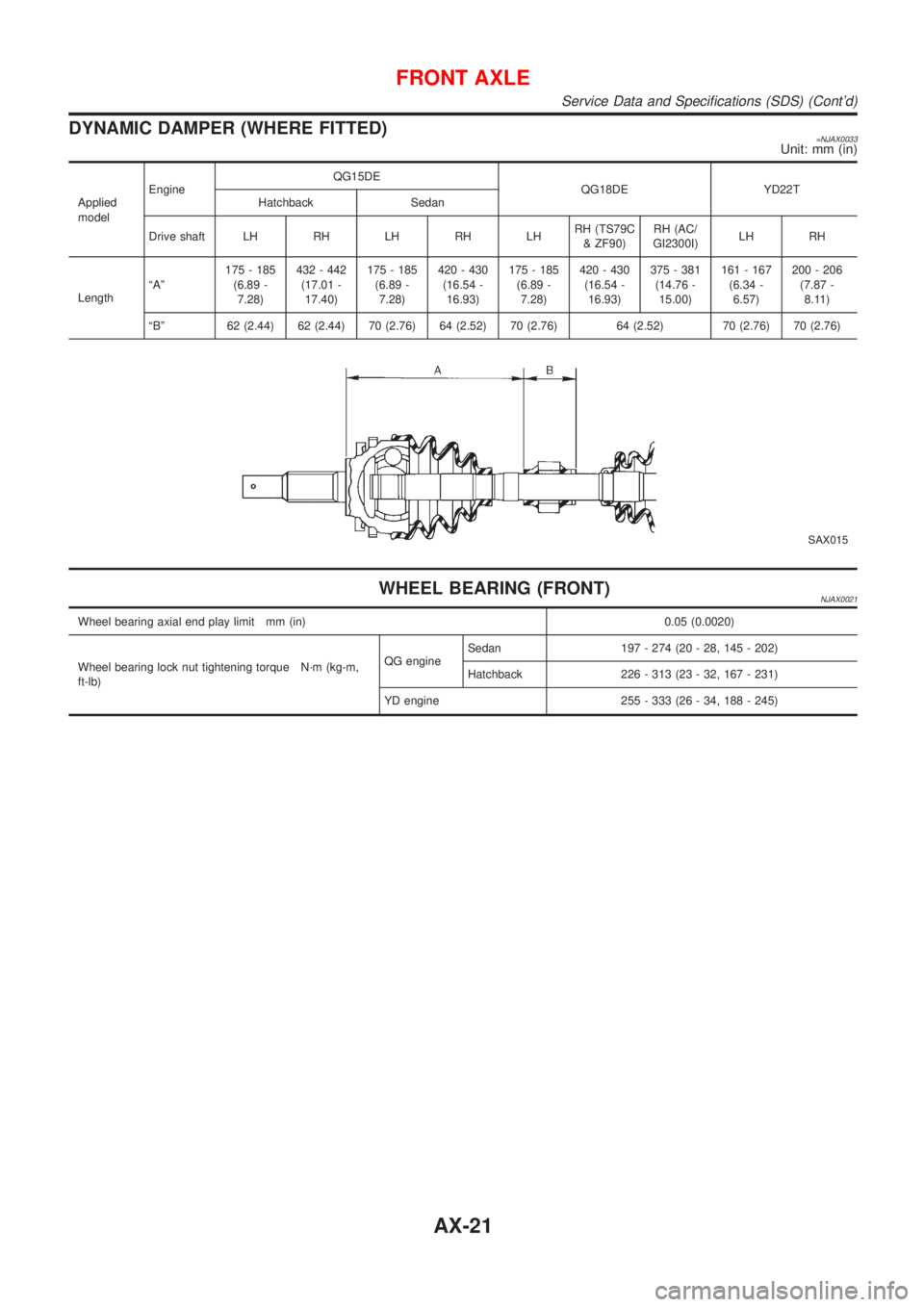
DYNAMIC DAMPER (WHERE FITTED)=NJAX0033Unit: mm (in)
Applied
modelEngineQG15DE
QG18DE YD22T
Hatchback Sedan
Drive shaft LH RH LH RH LHRH (TS79C
& ZF90)RH (AC/
GI2300I)LH RH
LengthªAº175 - 185
(6.89 -
7.28)432 - 442
(17.01 -
17.40)175 - 185
(6.89 -
7.28)420 - 430
(16.54 -
16.93)175 - 185
(6.89 -
7.28)420 - 430
(16.54 -
16.93)375 - 381
(14.76 -
15.00)161 - 167
(6.34 -
6.57)200 - 206
(7.87 -
8.11)
ªBº 62 (2.44) 62 (2.44) 70 (2.76) 64 (2.52) 70 (2.76) 64 (2.52) 70 (2.76) 70 (2.76)
SAX015
WHEEL BEARING (FRONT)NJAX0021
Wheel bearing axial end play limit mm (in) 0.05 (0.0020)
Wheel bearing lock nut tightening torque N´m (kg-m,
ft-lb)QG engineSedan 197 - 274 (20 - 28, 145 - 202)
Hatchback 226 - 313 (23 - 32, 167 - 231)
YD engine 255 - 333 (26 - 34, 188 - 245)
FRONT AXLE
Service Data and Specifications (SDS) (Cont'd)
AX-21
Page 510 of 2898

SBR686C
Precautions
PRECAUTIONSNJAX0022+When installing each rubber part, final tightening must be
carried out under unladen condition* with tires on ground.
*: Fuel, radiator coolant and engine oil full. Spare tire, jack,
hand tools and mats in designated positions.
+Use flare nut wrench when removing or installing brake
tubes.
+After installing removed suspension parts, check wheel
alignment.
+Do not jack up at the trailing arm and lateral link.
+Always torque brake lines when installing.
Preparation
SPECIAL SERVICE TOOLSNJAX0032
Tool number
Tool nameDescription
KV40104710
Drift
NT474
Install ABS sensor rotor
a: 76.3 mm (3.004 in) dia.
b: 67.9 mm (2.673 in) dia.
ST3072000
Drift
NT115
Install ABS sensor rotor
a: 77 mm (3.03 in) dia.
b: 55.5 mm (2.185 in) dia.
COMMERCIAL SERVICE TOOLSNJAX0024
Tool name Description
1 Flare nut crowfoot
2 Torque wrench
NT360
Removing and installing brake piping
a: 10 mm (0.39 in)
REAR AXLE
Precautions
AX-22
Page 511 of 2898
Noise, Vibration and Harshness (NVH)
Troubleshooting
NJAX0025Refer to ªNoise, Vibration and Harshness (NVH) Troubleshootingº,
ªFRONT AXLEº, AX-3.
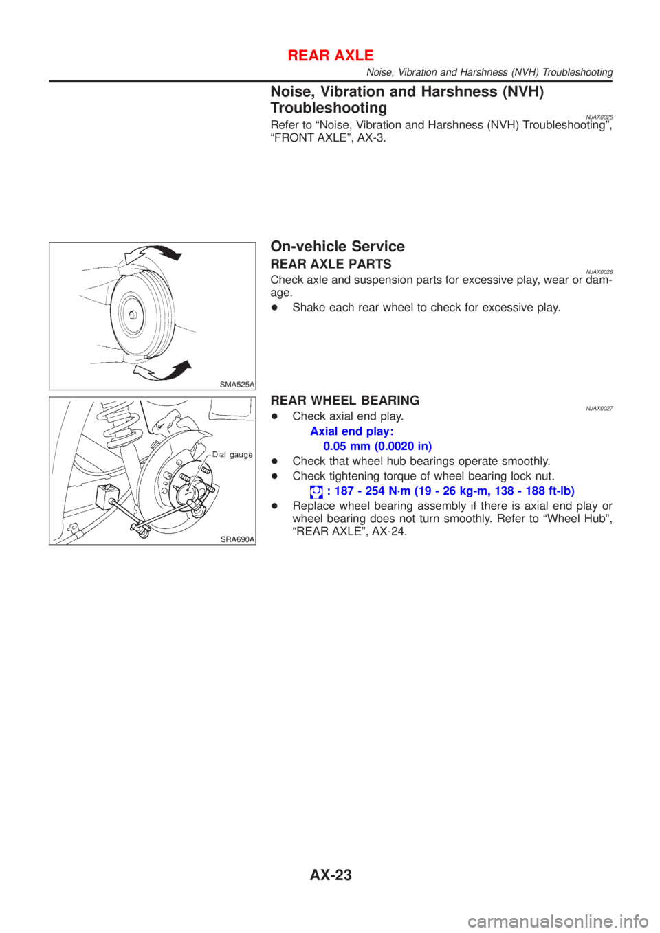
SMA525A
On-vehicle Service
REAR AXLE PARTSNJAX0026Check axle and suspension parts for excessive play, wear or dam-
age.
+Shake each rear wheel to check for excessive play.
SRA690A
REAR WHEEL BEARINGNJAX0027+Check axial end play.
Axial end play:
0.05 mm (0.0020 in)
+Check that wheel hub bearings operate smoothly.
+Check tightening torque of wheel bearing lock nut.
: 187 - 254 N´m (19 - 26 kg-m, 138 - 188 ft-lb)
+Replace wheel bearing assembly if there is axial end play or
wheel bearing does not turn smoothly. Refer to ªWheel Hubº,
ªREAR AXLEº, AX-24.
REAR AXLE
Noise, Vibration and Harshness (NVH) Troubleshooting
AX-23